Download to read offline
![Design and Implementation of A Water Level and
Pump Motor Controlling System
Asad Ali Jecko
Department of Electrical Technology
UCEP Institute of Science & Technology (UIST)
UCEP Bangladesh, Dhaka, Bangladesh
asad@uist.edu.bd
Sumon Biswas
Department of Electrical Technology
UCEP Institute of Science & Technology (UIST)
UCEP Bangladesh, Dhaka, Bangladesh
sumon.eee09@gmail.com
Mst. Sharmin Akter
Department of Electrical Technology
UCEP Institute of Science & Technology (UIST)
UCEP Bangladesh, Dhaka, Bangladesh
asharmin90@gmail.com
Zabir Arkam Akhond
Department of Electrical Technology
UCEP Institute of Science & Technology (UIST)
UCEP Bangladesh, Dhaka, Bangladesh
zabirarkam27@gmail.com
Md. Moshiur Rahman
Department of Electrical Technology
UCEP Institute of Science & Technology (UIST)
UCEP Bangladesh, Dhaka, Bangladesh
Yeasin Ahmed Siam
Department of Electrical Technology
UCEP Institute of Science & Technology (UIST)
UCEP Bangladesh, Dhaka, Bangladesh
Abstract— Drinking pure water and using clean water are
more important for human body. It is observed commonly in
our country that people are not aware of using water in
households. Besides the natural sources of clean and pure
water on the surface are decreasing day by day. On the other
hand, the demand for clean and pure water is increasing due to
rapid population growth in our country. It is observed in
households that much water is being wasted due to overflow in
water tank. Besides, much electric power is being lost due to
lack of water pump controlling system. In this project, a
calculation has been shown on economic effect due to overflow
of water. To address the problem, a water level and water
pump controlling system has been designed. In the
development of the system a float switch, two indicator lamps,
a relay, a magnetic contactor and an alarm have been used. In
this project, relay plays an important role in safety which
keeps the whole system out of power when accidently or due
system fault the water is electrified. Though whole system goes
out of power, relay will remain active by taking power from
supply though itself. The system has gone under many trials.
Finally, a successful and effective operation has been observed
under different environments. The main advantages of the
sophisticated system are environmentally friendliness, easiness
of installation and maintenance, cost effectiveness and
availability of its parts.
Keywords—Water, population, households, overflow,
environments & sophisticated.
I. INTRODUCTION
Water is one of the most important substances available in
nature. It is a basic necessity for existence of all life forms.
Without water most life forms will cease to exist. Around
eighty percent of human body is made up of water and so it
very essential for its existence. At this juncture humanity
has come to a crossroad because of careless use of scarce
natural resources like water.
Fig. 1: Clean Water [1].
The available water supply has been consistently going
down. The river and other sources of water are being
contaminated by factories and human civilization leaving
the water unfit for use. When the available water was found
to be insufficient the debate about the careful use and
conservation of water started establishing once again the
importance of water in human life.](https://image.slidesharecdn.com/designandimplementationofawaterlevelandpumpmotorcontrollingsystemfinalversion-200116125641/75/Design-and-implementation-of-a-water-level-and-pump-motor-controlling-system-final-version-1-2048.jpg)
![Fig. 2: A graphical distribution of the locations of water on Earth [2].
II. LITERATURE REVIEW
Considering the developments in technology, it is
only appropriate that new methods be developed to control
overflow of water in water reserve tank in households,
industries, hotels and multipurpose buildings, and to save
power and water. Researchers are doing research in
developing new methods to address the issue [3-7]. A
number of journal papers and patents on the subject of water
management and water level controller development are
found. The research publications are largely on effort to
address and solve the overflow of water households,
industries, hotels and multipurpose buildings, and to save
power and water. [8-12]. However, few, if any, protections
described in the literature have been implemented in the
popular construction of water level. There have been almost
no adaptations of sophisticated technology from other
appliances for the water level controller and pump
controlling system, as has been done for this paper [13-15].
More complex available applications are not so portable,
and are costly and difficult to implement. Some researchers
have made smart systems based on microcontrollers but
these are not more efficient. Many companies are doing
research to develop smarter, reliable and efficient water
level controller and pump controlling system [16-18].
III. METHODOLOGY
Fig. 3: Block diagram of the water level and pump motor controlling
system.
Fig. 3 shows the block diagram of the water level and pump
motor controlling system. A relay has been used for
protection of the whole system which will save the people
from electric shock in case of system fault and water
electrification. We know relay has two types of contact.
These are NC (Normally Closed) and NO (normally Open).
Here relay is connected in a process where primarily relay
will remain inactive until water is electrified. When water
will be electrified due to system fault or float switch leakage,
then relay will get power from water and it will be active
and will cut off the system from power supply. At the same
time, relay will get power from supply through itself to
remain active. When relay will be active, it will provide
power to indicator lamp and buzzer to give an alarm. The
indicator lamp and the buzzer have been used for the
indication of system fault. A float switch has been used to
control the pump motor which works according to the water
level. A magnetic contactor has been used to provide power
for pump motor from main power supply.
IV. WORKING PRINCIPLE OF THE DRIVER IMPAIRMENT
MONITORING SYSTEMTHE WATER LEVEL AND PUMP MOTOR
CONTROLLING SYSTEM
Fig. 4: Circuit diagram of the water level and pump motor controlling
system.
Fig. 4 illustrates the working principle of the water
level and pump motor controlling system. The system works
in three stages. Firstly, when the float switch will remain in
down position and the contact of the switch will remain in
normally closed (NC) position. At the same time magnetic
contactor will be active and will supply power to the motor
through its normally open (NO) contact. Then the motor will
start to pump water. Secondly, when the float switch will go
up and will remain in vertical position, the NC contact of the
switch will be changed into NC and the magnetic contactor
will be inactive and the motor will stop to pump water.
Thirdly, if the water is electrified because of any leakage or
fault of float switch, the relay will be active and it will shut
down the whole system and cut off the system’s power from
supply line. At the same time, the buzzer will give alarm
and the indicator lamp will give the indication of system
fault.
V. FLOW CHART OF THE WATER LEVEL AND PUMP MOTOR
CONTROLLING SYSTEM](https://image.slidesharecdn.com/designandimplementationofawaterlevelandpumpmotorcontrollingsystemfinalversion-200116125641/75/Design-and-implementation-of-a-water-level-and-pump-motor-controlling-system-final-version-2-2048.jpg)
![Fig. 7: Setup of the system
Fig. 8: View of the water level and pump motor controlling system
VII. CONCULUSION
The paper has described the design and implementation
of a proof of concept of the water level and pump motor
controlling system. The following future enhancement can
be included into proposed system.
1. Wireless controlling using app.
2. Live online water level monitoring system.
3. Solar power bank for emergency use.
REFERENCES
[1] https://www.pexels.com/photo/nature-water-drops-of-water-liquid-
40784/(Access on 22 August, 2019)
[2] https://en.wikipedia.org/wiki/Water_distribution_on_Earth(Access
on 22 August, 2019)
[3] Zahir, Ebad, Sudipta Das, Md Hasnat Rabbi, Samiul Huq, and Md
Bakir Hossain. "Implementation of a Fiberoptic Sensor to
Detect Change in Liquid Level and Change in Concentration of
Solute in a Water Reservoir." In 2019 International
Conference on Robotics, Electrical and Signal Processing
Techniques (ICREST), pp. 258-262. IEEE, 2019.
[4] Zahir, Ebad, Sudipta Das, Md Hasnat Rabbi, Samiul Huq, and Md
Bakir Hossain. "Implementation of a Fiberoptic Sensor to
Detect Change in Liquid Level and Change in Concentration of
Solute in a Water Reservoir." In 2019 International
Conference on Robotics, Electrical and Signal Processing
Techniques (ICREST), pp. 258-262. IEEE, 2019.
[5] Shakir, Abdul Alim, Faysal Hakim, Mirza Rasheduzzaman, Sagar
Chakraborty, Tausif Uddin Ahmed, and Sazzad Hossain.
"Design and Implementation of SENSEP ACK: An IoT
Based Mushroom Cultivation Monitoring System." In 2019
International Conference on Electrical, Computer and
Communication Engineering (ECCE), pp. 1-6. IEEE, 2019.
[6] Mallikarjun.G.Hudedmani, Nagaraj. S. N, Shrikanth.B.J, Ali Adil
Sha, Pramod.G, “ Flexible Automatic Water Level Controller and
Indicator” World Journal of Technology, Engineering and
Research, Volume 3, Issue-1, pp 359-366, 2018.
[7] Ajinkya Kaner, Milind Rane, “Automatic Water Level Indicator &
Controller”, International Journal of Advanced Research in
Electronics and Communication Engineering (IJARECE), ISSN:
2278 – 909X, Volume 6, Issue 11, November 2017.
[8] Dipanjan Rakshit, Bijit Baral, Saikat Datta, Pratyusha Biswas Deb,
Priyanjali Mukherjee, Shaon Paul, “Water Level Indicator”,
International Journal of Scientific & Engineering Research, ISSN:
2229-5518, Volume 7, Issue -4, April-2016.
[9] Shamim Pathan, Praseed Kumar, Sarvesh Tendolkar, Vivek Patil4,
Sujoy Lucas, Aditya Daithankarg, “Automatic control of a pump
system for water level using Microcontroller and LabVIEW”,
International Research Journal of Engineering and Technology
(IRJET), e-ISSN: 2395 -0056, Volume - 03, Issue – 05, May-2016.
[10] Erua J. Band, Anyasi, F. I. , “Design of an Automatic Water Level
Controller Using Mercury Float Switch”, IOSR Journal of
Electronics and Communication Engineering (IOSR-JECE), e-
ISSN: 2278-2834, Volume 9, Issue 2, Ver. II, PP 16-21, (Mar -
Apr. 2014).
[11] Ahmed Abdullah, Md. Galib Anwar, Takilur Rahman, Sayera
Aznabi, “Water Level Indicator with Alarms Using PIC
Microcontroller”, American Journal of Engineering Research
(AJER), e-ISSN: 2320-0847, Volume-4, Issue-7, pp 88-92, 2015.
[12] Sanam Pudasaini, Anuj Pathak, Sukirti Dhakal, Milan Paudel,
“Automatic Water Level Controller with Short Messaging Service
(SMS) Notification”, International Journal of Scientific and
Research Publications, ISSN: 2250-3153, Volume 4, Issue- 9,
September 2014,
[13] B. Priyanka, M. Himavarsha, G. Srividhya, G. Sathish, A. Anroop,
K. B. V. S. R. Subrahmanyam, “Intelligent Water Pump
Controller”, International Journal Of Advances In Electrical Power
System And Information Technology (IJAEPSIT), ISSN (Online):
2395-6151, Volume-2, Issue-2, 2016.
[14] Naman Gupta, Sanjay Kumar, Manit Kumar, Divisha Mathur,
Enjila Jilani, “Wireless Water Level Controller Using Zigbee”,
International Journal of Latest Technology in Engineering,
Management & Applied Science, ISSN 2278 – 2540, Volume V,
Issue- IV, April 2016.
[15] Mr.Muthamil Selvan.S , Aratrika Roy, Kurnal Pratap Singh,
Ashutosh Kumar, “Automatic Water Level Indicator Using
Ultrasonic Sensor And Gsm Module”, International Journal Of
Engineering Research & Technology (IJARIIE), ISSN(O): 2395-
4396, Vol-4 Issue-5 2018.
[16] Asaad Ahmed Mohammedahmed Eltaieb, Zhang Jian Min,
“Automatic Water Level Control System”, International Journal of
Science and Research (IJSR), ISSN (Online): 2319-7064, Volume
4 Issue-12, December 2015.
[17] Amrit Kumar Panigrahi, Chandan Kumar Singh, Diwesh Kumar,
Nemisha Hota, “Tank Water Level Indicator & Controller Using
Arduino”, International Journal of Advanced Research in
Electrical, Electronics and Instrumentation Engineering, ISSN
(Online): 2278 – 8875, Vol. 6, Issue 3, March 2017.
[18] Ejiofor Virginia Ebere, Oladipo Onaolapo Francisca,
“Microcontroller based Automatic Water level Control System”,](https://image.slidesharecdn.com/designandimplementationofawaterlevelandpumpmotorcontrollingsystemfinalversion-200116125641/75/Design-and-implementation-of-a-water-level-and-pump-motor-controlling-system-final-version-4-2048.jpg)


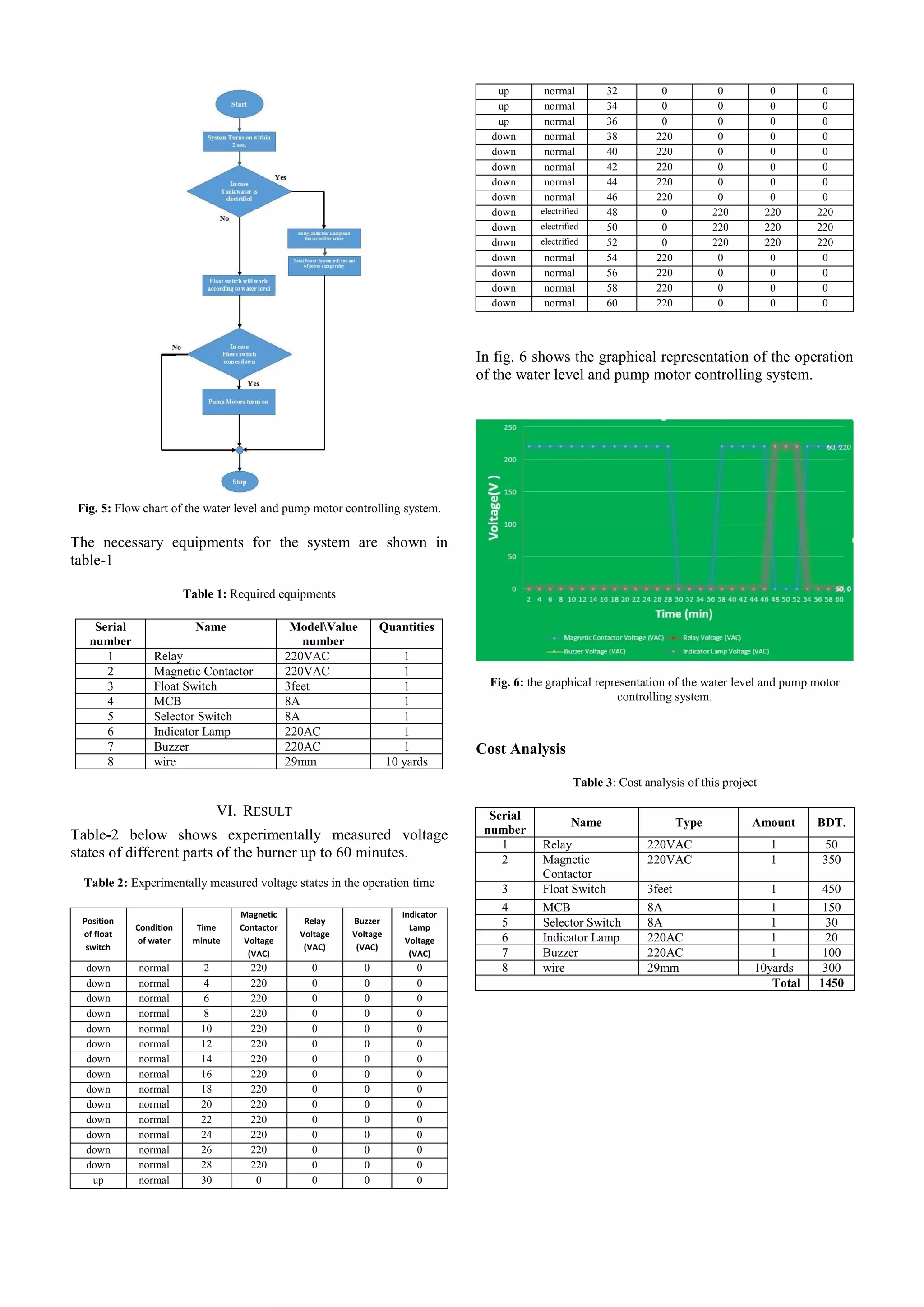
The document details the design and implementation of a water level and pump motor controlling system aimed at reducing water waste and power loss in households. It includes various components such as a float switch, relay, and alarm for effective system operation and safety. The project emphasizes environmental sustainability and the need for better water management in light of increasing demand and declining natural water resources.