Download to read offline
![International Research Journal of Engineering and Technology (IRJET) e-ISSN: 2395-0056
Volume: 06 Issue: 05 | May 2019 www.irjet.net p-ISSN: 2395-0072
© 2019, IRJET | Impact Factor value: 7.211 | ISO 9001:2008 Certified Journal | Page 7795
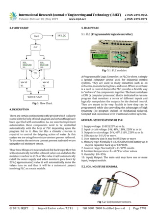
Fig: 4(a) Model 1( side view)
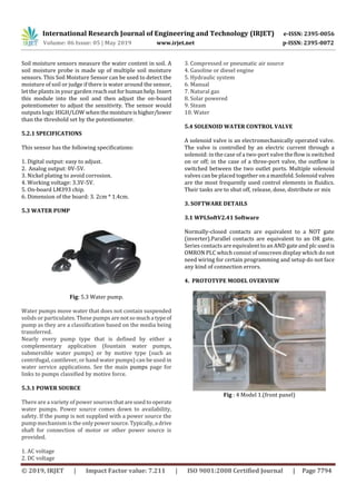
Fig: 4(b) Model 2( PLC unit)
5. CONCLUSION
We conclude that the system reduces water Consumption
and hence minimizes the wastage of water. In this system as
we provide controlled supply of water and fertilizers to the
crop it improves the Productivity. Also due to an automated
system the manpower is reduced. By implementing such a
system using plc and sensors we can increase Agricultural
yield and upgrade Indian economy.
6. ACKNOWLEDGEMENT
We would like to express our sincere thanks to Prof.Deven
Vatsal for his valuable guidance, great Support and
encouraged us to work hard. And we Also want to thanks
Electrical and Electronics Engineering department and our
college.
7. REFERENCES
[1] Prashant S. Patil, Shubham R. Alai, Ashish C. Malpure,
Prashant L. Patil, “An Intelligent and Automated Drip
Irrigation System Using Sensors Network Control System”,
International Journal of Innovative Research in Computer
and Communication Engineering, 2014.
[2]Chetna V. Maheshwari, Dipal Sindha, “Water Irrigation
system Using Controller”, International Journal of Advanced
Technology in Engineering and Science, 2014.
[3] Santosh, Sanket, Shriyo, Sugandha, Sakina, Priyanka
harsha, Anuradha Desai, “Plc Based Automated Drip
Irrigation”, International Journal of Current Research in
Multidisciplinary (IJCRM), 2016.
[4] Shweta Bopshetty, Mrunali Yadav, Rithvika Rae, Sheril
Silvister, Prof. Parth Sagar, “Monitoring and Controlling of
Drip Irrigation using IOT with Embedded Linux Board”,
International Journal ofAdvancedResearchinComputerand
Communication Engineering, 2017.
[5] Vaishnavi mantra,Namrata mohite, Aishwarya Patil,Prof.
Yadav NC. “Automatic Drip Irrigation Using PLC”,
International Research Journal of Engineering and
Technology (IRJET) 2018](https://image.slidesharecdn.com/irjet-v6i51139-191024100848/85/IRJET-Smart-Irrigation-System-using-Soil-Moisture-Sensor-and-PLC-4-320.jpg)

This document describes a smart irrigation system that uses soil moisture sensors and a programmable logic controller (PLC) to automate watering. The system aims to minimize water waste by only turning on pumps and supplying water when the soil moisture drops below a predefined threshold. Two sensors placed at different intervals will sense soil moisture levels and send data to the PLC. The PLC will compare the sensed values to the threshold and control solenoid valves and pumps accordingly to automatically supply water as needed based on soil dryness. The system is intended to provide the optimal required water to crops based on their demands and availability of electricity for pumping, reducing water consumption in agriculture through automation.