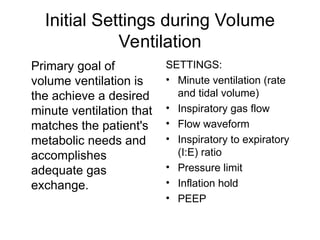
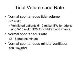
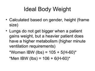
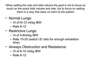
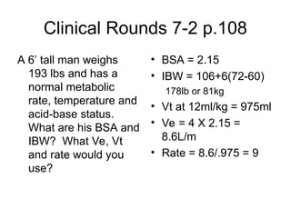
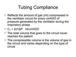
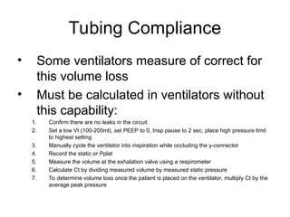
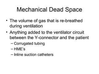
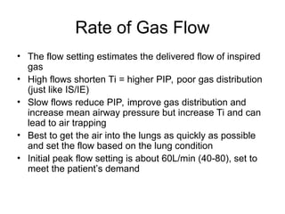
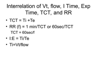
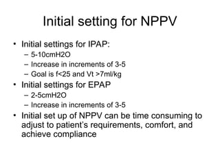
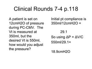
Initial Ventilator Settings
Chapter 7
Initial Settings during Volume
Ventilation
Primary goal of
volume ventilation is
the achieve a desired
minute ventilation that
matches the patient's
metabolic needs and
accomplishes
adequate gas
exchange.
SETTINGS:
• Minute ventilation (rate
and tidal volume)
• Inspiratory gas flow
• Flow waveform
• Inspiratory to expiratory
(I:E) ratio
• Pressure limit
• Inflation hold
• PEEP
Tidal Volume and Rate
• Normal spontaneous tidal volume
5-7 ml/kg
- Ventilated patients 6-12 ml/kg IBW for adults
and 5-10 ml/kg IBW for children and infants
• Normal spontaneous rate
12-18 breaths/minute
• Normal spontaneous minute ventilation
100ml/kgIBW
Ideal Body Weight
• Calculated based on gender, height (frame
size)
• Lungs do not get bigger when a patient
gains weight, but a heavier patient does
have a higher metabolism (higher minute
ventilation requirements)
*Women IBW (lbs) = 105 + 5(H-60)*
*Men IBW (lbs) = 106 + 6(H-60)*
When setting the rate and tidal volume the goal is not to focus so
much on the exact tidal volume and rate, but to focus on setting
them in a way that does no harm to the patient
• Normal Lungs:
– Vt of10-12 ml/kg IBW
– Rate 8-12
• Restrictive Lungs:
– Vt of 4-8ml/kg IBW
– Rate 15-25 (watch I:E ratio for enough exhalation
time)
• Airways Obstruction and Resistance:
– Vt of 8-10 ml/kg IBW
– Rate 8-12
Clinical Rounds 7-2 p.108
A 6’ tall man weighs
193 lbs and has a
normal metabolic
rate, temperature and
acid-base status.
What are his BSA and
IBW? What Ve, Vt
and rate would you
use?
• BSA = 2.15
• IBW = 106+6(72-60)
178lb or 81kg
• Vt at 12ml/kg = 975ml
• Ve = 4 X 2.15 =
8.6L/m
• Rate = 8.6/.975 = 9
Tubing Compliance
• Reflects the amount of gas (ml) compressed in
the ventilator circuit for every cmH2O of
pressure generated by the ventilator during the
inspiratory phase
• CT = ΔV/ΔP ml/cmH2O
• The total volume that goes to the circuit never
reaches the patient
• The compressible volume is the volume of gas in
the circuit and varies depending on the type of
circuit
Tubing Compliance
• Some ventilators measure of correct for
this volume loss
• Must be calculated in ventilators without
this capability:
1. Confirm there are no leaks in the circuit
2. Set a low Vt (100-200ml), set PEEP to 0, Insp pause to 2 sec, place high pressure limit
to highest setting
3. Manually cycle the ventilator into inspiration while occluding the y-connector
4. Record the static or Pplat
5. Measure the volume at the exhalation valve using a respirometer
6. Calculate Ct by dividing measured volume by measured static pressure
7. To determine volume loss once the patient is placed on the ventilator, multiply Ct by the
average peak pressure
Box 7-3 p. 111
A patient’s estimated
Vt is 400ml. Her PIP
is 30cmH20 and the
Ct is 2.9ml/cmH2O.
What is the actual
volume delivery to the
patient?
Vol lost = 2.9 X 30 =
87ml
Actual vol delivered=
400-87= 313ml
Mechanical Dead Space
• The volume of gas that is re-breathed
during ventilation
• Anything added to the ventilator circuit
between the Y-connector and the patient
– Corrugated tubing
– HME’s
– Inline suction catheters
Rate of Gas Flow
• The flow setting estimates the delivered flow of inspired
gas
• High flows shorten Ti = higher PIP, poor gas distribution
(just like IS/IE)
• Slow flows reduce PIP, improve gas distribution and
increase mean airway pressure but increase Ti and can
lead to air trapping
• Best to get the air into the lungs as quickly as possible
and set the flow based on the lung condition
• Initial peak flow setting is about 60L/min (40-80), set to
meet the patient’s demand
Interrelation of Vt, flow, I Time, Exp
Time, TCT, and RR
• TCT = Ti +Te
• RR (f) = 1 min/TCT or 60sec/TCT
TCT = 60sec/f
• I:E = Ti/Te
• Ti=Vt/flow
Clinical Rounds 7-3 p.113
A time cycled ventilator
is set with the following
parameter: Vt=500 f=12
I:E =1:4. If a constant
flow waveform is used,
what is the inspiratory
gas flow?
TCT = 60/12 =5 sec
Ti= 5sec/(1+4)= 1sec
Te=TCT-Ti 5-1=4
Flow= .5L/1sec x
60sec/min=
30L/min
You are asked to ventilate a 63yr old
female pt in severe CHF. She is 5’8” and
185lbs. Her ABG on a non-rebreather: ph
7.18, PaCO2 83, PaO2 98 HCO3 31. She
is orally intubated with a 7.5 ETT.
Determine the following:
Vt
f
I:E
flow
Flow Patterns
selection depends of lung condition
• Constant Flow – Square
waveform
– Provides the shorted Ti
• Ascending Ramp
– Not generally used
• Sine Flow
– Tapered flow may more
evenly distribute gas to
lungs
• Descending Ramp
– Attempts to meet pt flow
demand, flow is greatest at
the beginning of inspiration
Comparing the descending ramp
and constant flow
• The descending flow pattern has a lower PIP
and higher Paw which may improve gas
distribution, reduce dead space ventilation, and
increase oxygenation by increasing mean and
plateau pressures
• Waveform selection is dependent on deciding
which is more important for the patient: concerns
of high PIP or mean airway pressure
• High PIP does not always increase the risk of
damage to lung parenchyma as much of this
pressure is dissipated in overcoming airway
resistance and may not reach the alveolar level
Inspiratory Pause
• A maneuver that prevents the expiratory valve
from opening for a short time at the end of
inspiration
• Most frequently used to obtain an estimate of the
plateau pressure
• In theory it could be used with each breath to
improve distribution of air in the lungs, provide
optimum V/Q matching and reduce Vd/Vt ratios,
but it significantly increases Paw and reduces
pulmonary blood flow
Initial Settings during Pressure
Ventilation
• Pressure ventilation has
the advantage of limiting
pressures to avoid over-
inflation and providing
flow on demand
• The change in pressure
between the baseline and
PIP is set to establish the
Vt delivery (PEEP
compensation)
SETTINGS
• Baseline pressure (PEEP)
• IP is set to match the plateau
pressure if switching from
volume ventilation or started at
a low pressure (10-15cmH20)
and adjusted to attain the
desired volume
• Rate, IT, and I:E are set just as
in volume ventilation
Initial Settings during Pressure
Support Ventilation
• PSV is usually started
to begin the process
of discontinuing
ventilation
• The pressure is set at
a level to prevent a
fatiguing workload on
the respiratory
muscles
• Level of PS can be
set based on airway
resistance or equal to
the Pta (PIP-Pplat)
• Regardless of the
initial setting it is
important to adjust to
an adequate level
PSV GOALS
• To help increase the Vt (5-12ml/kg)
• To decrease the respiratory rate (<25-30)
• To decrease the work of breathing
associated with breathing through an
artificial airway
Initial setting for NPPV
• Initial settings for IPAP:
– 5-10cmH2O
– Increase in increments of 3-5
– Goal is f<25 and Vt >7ml/kg
• Initial settings for EPAP
– 2-5cmH2O
– Increase in increments of 3-5
• Initial set up of NPPV can be time consuming to
adjust to patient’s requirements, comfort, and
achieve compliance
Clinical Rounds 7-4 p.118
A patient is set on
12cmH2O of pressure
during PC-CMV. The
Vt is measured at
350ml, but the
desired Vt is 550ml,
how would you adjust
the pressure?
Initial pt compliance is
350ml/12cmH2O =
29.1
So using ΔP = ΔV/C
550ml/29.1=
18.9cmH2O

InitialVentilatorSettings of mechanical ventilation.ppt

  • 1.
  • 2.
    Initial Settings duringVolume Ventilation Primary goal of volume ventilation is the achieve a desired minute ventilation that matches the patient's metabolic needs and accomplishes adequate gas exchange. SETTINGS: • Minute ventilation (rate and tidal volume) • Inspiratory gas flow • Flow waveform • Inspiratory to expiratory (I:E) ratio • Pressure limit • Inflation hold • PEEP
  • 3.
    Tidal Volume andRate • Normal spontaneous tidal volume 5-7 ml/kg - Ventilated patients 6-12 ml/kg IBW for adults and 5-10 ml/kg IBW for children and infants • Normal spontaneous rate 12-18 breaths/minute • Normal spontaneous minute ventilation 100ml/kgIBW
  • 4.
    Ideal Body Weight •Calculated based on gender, height (frame size) • Lungs do not get bigger when a patient gains weight, but a heavier patient does have a higher metabolism (higher minute ventilation requirements) *Women IBW (lbs) = 105 + 5(H-60)* *Men IBW (lbs) = 106 + 6(H-60)*
  • 5.
    When setting therate and tidal volume the goal is not to focus so much on the exact tidal volume and rate, but to focus on setting them in a way that does no harm to the patient • Normal Lungs: – Vt of10-12 ml/kg IBW – Rate 8-12 • Restrictive Lungs: – Vt of 4-8ml/kg IBW – Rate 15-25 (watch I:E ratio for enough exhalation time) • Airways Obstruction and Resistance: – Vt of 8-10 ml/kg IBW – Rate 8-12
  • 6.
    Clinical Rounds 7-2p.108 A 6’ tall man weighs 193 lbs and has a normal metabolic rate, temperature and acid-base status. What are his BSA and IBW? What Ve, Vt and rate would you use? • BSA = 2.15 • IBW = 106+6(72-60) 178lb or 81kg • Vt at 12ml/kg = 975ml • Ve = 4 X 2.15 = 8.6L/m • Rate = 8.6/.975 = 9
  • 7.
    Tubing Compliance • Reflectsthe amount of gas (ml) compressed in the ventilator circuit for every cmH2O of pressure generated by the ventilator during the inspiratory phase • CT = ΔV/ΔP ml/cmH2O • The total volume that goes to the circuit never reaches the patient • The compressible volume is the volume of gas in the circuit and varies depending on the type of circuit
  • 8.
    Tubing Compliance • Someventilators measure of correct for this volume loss • Must be calculated in ventilators without this capability: 1. Confirm there are no leaks in the circuit 2. Set a low Vt (100-200ml), set PEEP to 0, Insp pause to 2 sec, place high pressure limit to highest setting 3. Manually cycle the ventilator into inspiration while occluding the y-connector 4. Record the static or Pplat 5. Measure the volume at the exhalation valve using a respirometer 6. Calculate Ct by dividing measured volume by measured static pressure 7. To determine volume loss once the patient is placed on the ventilator, multiply Ct by the average peak pressure
  • 9.
    Box 7-3 p.111 A patient’s estimated Vt is 400ml. Her PIP is 30cmH20 and the Ct is 2.9ml/cmH2O. What is the actual volume delivery to the patient? Vol lost = 2.9 X 30 = 87ml Actual vol delivered= 400-87= 313ml
  • 10.
    Mechanical Dead Space •The volume of gas that is re-breathed during ventilation • Anything added to the ventilator circuit between the Y-connector and the patient – Corrugated tubing – HME’s – Inline suction catheters
  • 11.
    Rate of GasFlow • The flow setting estimates the delivered flow of inspired gas • High flows shorten Ti = higher PIP, poor gas distribution (just like IS/IE) • Slow flows reduce PIP, improve gas distribution and increase mean airway pressure but increase Ti and can lead to air trapping • Best to get the air into the lungs as quickly as possible and set the flow based on the lung condition • Initial peak flow setting is about 60L/min (40-80), set to meet the patient’s demand
  • 12.
    Interrelation of Vt,flow, I Time, Exp Time, TCT, and RR • TCT = Ti +Te • RR (f) = 1 min/TCT or 60sec/TCT TCT = 60sec/f • I:E = Ti/Te • Ti=Vt/flow
  • 13.
    Clinical Rounds 7-3p.113 A time cycled ventilator is set with the following parameter: Vt=500 f=12 I:E =1:4. If a constant flow waveform is used, what is the inspiratory gas flow? TCT = 60/12 =5 sec Ti= 5sec/(1+4)= 1sec Te=TCT-Ti 5-1=4 Flow= .5L/1sec x 60sec/min= 30L/min
  • 14.
    You are askedto ventilate a 63yr old female pt in severe CHF. She is 5’8” and 185lbs. Her ABG on a non-rebreather: ph 7.18, PaCO2 83, PaO2 98 HCO3 31. She is orally intubated with a 7.5 ETT. Determine the following: Vt f I:E flow
  • 15.
    Flow Patterns selection dependsof lung condition • Constant Flow – Square waveform – Provides the shorted Ti • Ascending Ramp – Not generally used • Sine Flow – Tapered flow may more evenly distribute gas to lungs • Descending Ramp – Attempts to meet pt flow demand, flow is greatest at the beginning of inspiration
  • 16.
    Comparing the descendingramp and constant flow • The descending flow pattern has a lower PIP and higher Paw which may improve gas distribution, reduce dead space ventilation, and increase oxygenation by increasing mean and plateau pressures • Waveform selection is dependent on deciding which is more important for the patient: concerns of high PIP or mean airway pressure • High PIP does not always increase the risk of damage to lung parenchyma as much of this pressure is dissipated in overcoming airway resistance and may not reach the alveolar level
  • 17.
    Inspiratory Pause • Amaneuver that prevents the expiratory valve from opening for a short time at the end of inspiration • Most frequently used to obtain an estimate of the plateau pressure • In theory it could be used with each breath to improve distribution of air in the lungs, provide optimum V/Q matching and reduce Vd/Vt ratios, but it significantly increases Paw and reduces pulmonary blood flow
  • 18.
    Initial Settings duringPressure Ventilation • Pressure ventilation has the advantage of limiting pressures to avoid over- inflation and providing flow on demand • The change in pressure between the baseline and PIP is set to establish the Vt delivery (PEEP compensation) SETTINGS • Baseline pressure (PEEP) • IP is set to match the plateau pressure if switching from volume ventilation or started at a low pressure (10-15cmH20) and adjusted to attain the desired volume • Rate, IT, and I:E are set just as in volume ventilation
  • 19.
    Initial Settings duringPressure Support Ventilation • PSV is usually started to begin the process of discontinuing ventilation • The pressure is set at a level to prevent a fatiguing workload on the respiratory muscles • Level of PS can be set based on airway resistance or equal to the Pta (PIP-Pplat) • Regardless of the initial setting it is important to adjust to an adequate level
  • 20.
    PSV GOALS • Tohelp increase the Vt (5-12ml/kg) • To decrease the respiratory rate (<25-30) • To decrease the work of breathing associated with breathing through an artificial airway
  • 21.
    Initial setting forNPPV • Initial settings for IPAP: – 5-10cmH2O – Increase in increments of 3-5 – Goal is f<25 and Vt >7ml/kg • Initial settings for EPAP – 2-5cmH2O – Increase in increments of 3-5 • Initial set up of NPPV can be time consuming to adjust to patient’s requirements, comfort, and achieve compliance
  • 22.
    Clinical Rounds 7-4p.118 A patient is set on 12cmH2O of pressure during PC-CMV. The Vt is measured at 350ml, but the desired Vt is 550ml, how would you adjust the pressure? Initial pt compliance is 350ml/12cmH2O = 29.1 So using ΔP = ΔV/C 550ml/29.1= 18.9cmH2O