This document discusses circuit elements and their behavior in the time and frequency domains. It describes:
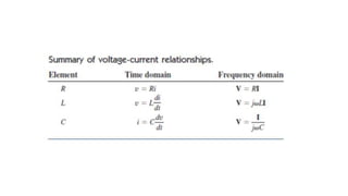
1) How resistors, inductors, and capacitors are modeled using phasors, with the voltage-current relationships transformed to the frequency domain.
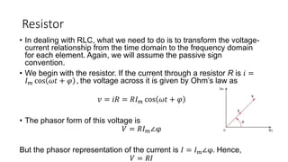
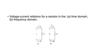
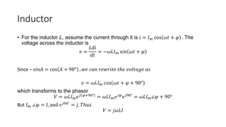
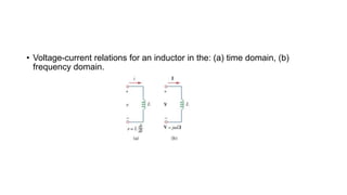
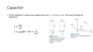
2) That resistors follow Ohm's law, inductors have voltage proportional to rate of current change, and capacitors have current proportional to rate of voltage change.
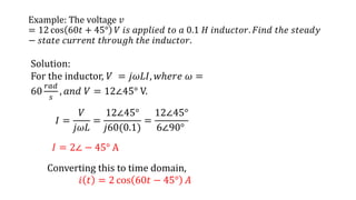
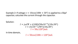
3) How to calculate steady-state current through an inductor or capacitor given the applied voltage using the phasor representations.
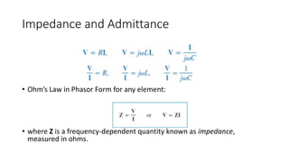
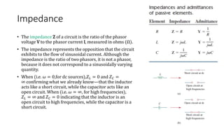
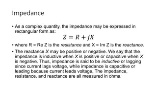
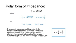
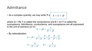
4) That impedance is the ratio of voltage to current in a circuit, accounting for both resistance and reactance, and can be expressed as a complex quantity in rectangular