Downloaded 28 times
![International
OPEN ACCESS Journal
Of Modern Engineering Research (IJMER)
| IJMER | ISSN: 2249–6645 | www.ijmer.com | Vol. 4 | Iss.7| July. 2014 | 1|
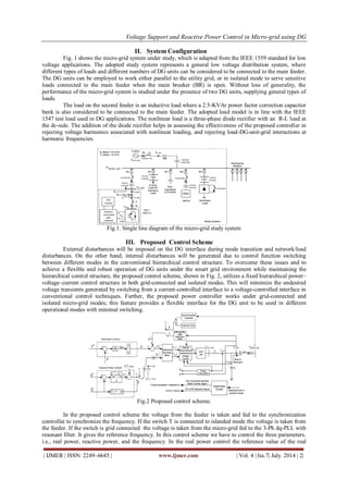
Voltage Support and Reactive Power Control in Micro-grid using DG Nagashree. J. R1, Vasantha Kumara. T. M2, Narasimhegowda3 1 4th sem, M.Tech,Power system engineering, Dept. of E&E Engg., Adichunchanagiri Institute of Technology, Chickmaglur, Karnataka 2 M.Tech,LMISTE,Asst. Prof., Dept. of E&E Engg., Adichunchanagiri Institute of Technology, Chickmaglur, Karnanataka 3 M.Tech,PGDCA,LMISTE Associate.Prof., Dept. of E&E Engg., Adichunchanagiri Institute of Technology, Chickmaglur, Karnataka
I. Introduction
The distribution system is an important part of an electric power system. As stated in[1], the capital investment in the distribution system constitutes a significant portionof the total amount spent in theentire power system. Due to the recent marketderegulation, this portion may become even larger. Furthermore, since the distributionsystems operate at the low voltage levels, the losses are usually higher compared tothose in other parts of the syste. Thus, the distribution system rates high ineconomic importance, which makes careful planning and design most worthwhile. Flexible operation of distributed generation (DG) units is a major objective in future smart power grids. The majority of DG units are interfaced to grid/load via power electronics converters. Current-controlled voltage-sourced inverters (VSIs) are commonly used for grid connection. Under the smart grid environment, DG units should be included in the system operational control framework, where they can be used to enhance system reliability by providing backup generation in isolated mode, and to provide ancillary services (e.g. voltage support and reactive power control) in the grid-connected mode. These operational control actions are dynamic in nature as they depend on the load/generation profile, demand-side management control, and overall network optimization controllers (e.g., grid reconfiguration and supervisory control actions) [4]. To achieve this vision, the DG interface should offer high flexibility and robustness in meeting a wide range of control functions, such as seamless transfer between grid-connected operation and islanded mode; seamless transfer between active/reactive power (PQ) and active power/voltage (PV) modes of operation in the grid connected mode; robustness against islanding detection delays; offering minimal control- function switching during mode transition; and maintaining a hierarchical control structure. Several control system improvements have been made to the hierarchical control structure to enhance the control performance of DG units either in grid- connected or isolated micro-grid systems [5]–[11]. However, subsequent to an islanding event, changing the controlling strategy from current to voltage control, in a hierarchical control framework, may result in serious voltage deviations especially when the islanding detection is delayed [12].
Abstract: Distribution Generators(DGs) are the renewable energy resource which can be connected to the grid. When it is connected to the grid it should be operated with controlled voltage and reactive power control. And in autonomous mode(i.e disconnected mode) it should operate in backup generation mode. These DGs are connected towards the micro grid operation. The proposed control system facilitates flexible and robust DG operational characteristics such as active/reactive power (PQ) or active power/voltage (PV) bus operation in the grid- connected mode, regulated power control in autonomous micro-grid mode, smooth transition between autonomous mode and PV or PQ grid connected modes and vice versa, reduced voltage distortion under heavily nonlinear loading conditions, and robust control performance under islanding detection delays. Evaluation results are presented to demonstrate the flexibility and effectiveness of the proposed controller.
Keywords: Distributed generation (DG), flexible control,micro-grids, smart distribution systems.](https://image.slidesharecdn.com/ijmer-47030106-140918025346-phpapp01/85/Voltage-Support-and-Reactive-Power-Control-in-Micro-grid-using-DG-1-320.jpg)
![Voltage Support and Reactive Power Control in Micro-grid using DG
| IJMER | ISSN: 2249–6645 | www.ijmer.com | Vol. 4 | Iss.7| July. 2014 | 6|
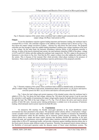
proposed control scheme uses the PI and PID controller and compares the results. The results of both will be the same but response time of the PI controller is more compare to the PID controller and also the system will be more stable in the PID controller compare to the PI controller. So the use of PID controller in control scheme is more beneficial than the use of PI controller. REFERENCES
[1]. Smart Grid: An Introduction U.S. Department of Energy, 2009.
[2]. E. M. Lightner and S. E. Widergren, ―An orderly transition to a trans-formed electricity systems,‖ IEEE Trans. Smart Grid, vol. 1, no. 1, pp. 3–10, Jun. 2010.
[3]. K. Moslehi and R. Kumar, ―A reliability perspective of smart grid,‖IEEE Trans. Smart Grid, vol. 1, no. 1, pp. 57–64, Jun. 2010.
[4]. G. T. Heydt, ―The next generation of power distribution systems,‖ IEEE Trans. Smart Grid, vol. 1, no. 3, pp. 225– 235, Nov. 2010.
[5]. A. Timbus, M. Liserre, R. Teodorescu, P. Rodriquez, and F. Blaabjerg, ―Evaluation of current controllers for distributed power generation systems,‖ IEEE Trans. Power Electron., vol. 24, no. 3, pp. 654–664, Mar.2009.
[6]. J. M. Guerrero, J. C. Vasquez, J. Matas, K. Vicuna, and M. Castilla, ―Hi-erarchical control of droop-controlled ac and dc microgrids—A general approach towards standardization,‖ IEEE Trans. Ind. Electron., to be published.
[7]. M. Liserre, R. Teodorescu, and F. Blaabjerg, ―Multiple harmonics control for three-phase grid converter systems with the use of PI-RES current controller in a rotating frame,‖ IEEE Trans. Power Electron., vol.21, no. 3, pp. 836– 841, May 2006.
[8]. Y. A.-R. I. Mohamed, ―Mitigation of dynamic, unbalanced and harmonic voltage disturbances using grid-connected inverters with LCL filter,‖ IEEE Trans. Ind. Electron., vol. 58, no. 9, pp. 3914–3924, Sep.2011.
[9]. S. Ahn, ―Power-sharing method of multiple distributed generators considering modes and configurations of a microgrid,‖ IEEE Trans. Power Del., vol. 25, no. 3, pp. 2007–2016, Jul. 2010.](https://image.slidesharecdn.com/ijmer-47030106-140918025346-phpapp01/85/Voltage-Support-and-Reactive-Power-Control-in-Micro-grid-using-DG-6-320.jpg)

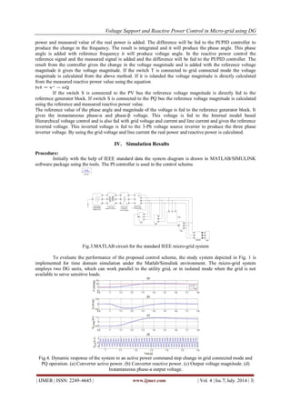
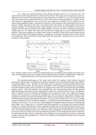
The document presents a control scheme for distributed generators in a microgrid system to provide voltage support and reactive power control. The control scheme uses a hierarchical power-voltage-current structure to facilitate flexible operation of distributed generators in both grid-connected and isolated microgrid modes. Simulation results show the control scheme enables: 1) Smooth transition between grid-connected and isolated modes while maintaining voltage regulation. 2) Robust performance during disturbances like islanding events and addition of nonlinear loads. 3) Accurate power sharing between distributed generators in both modes of operation. The study evaluates the control scheme's performance under different operating conditions and demonstrates its effectiveness in providing flexible and robust control of distributed generators in a microgrid system.


