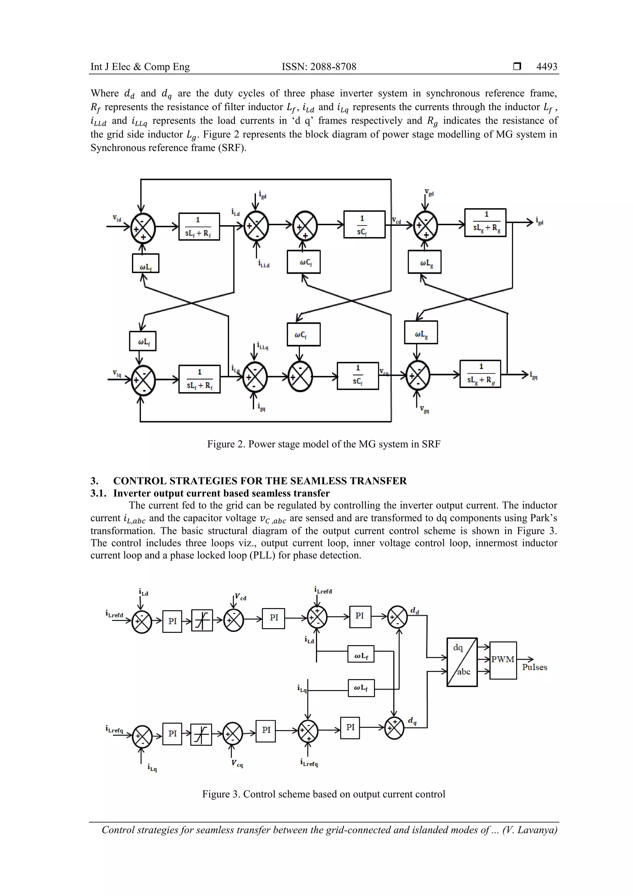
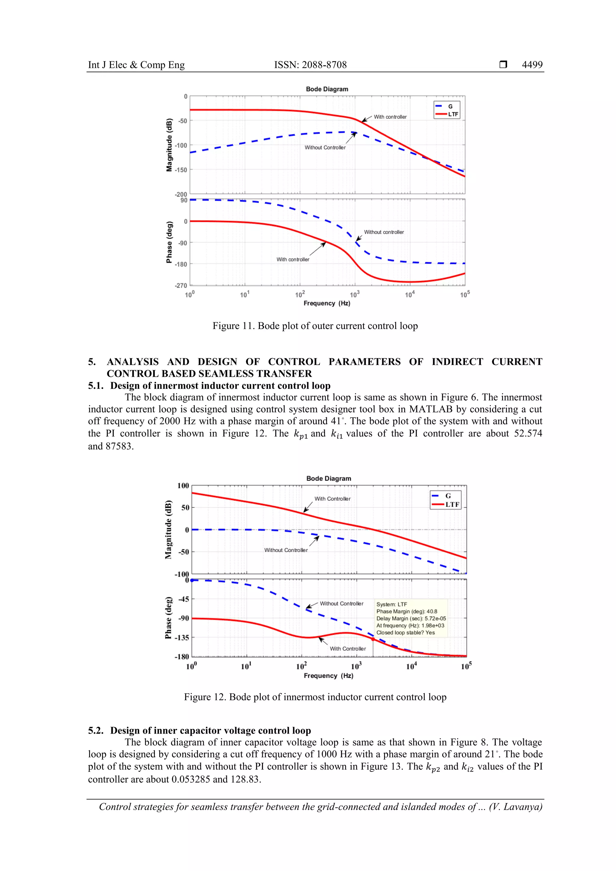
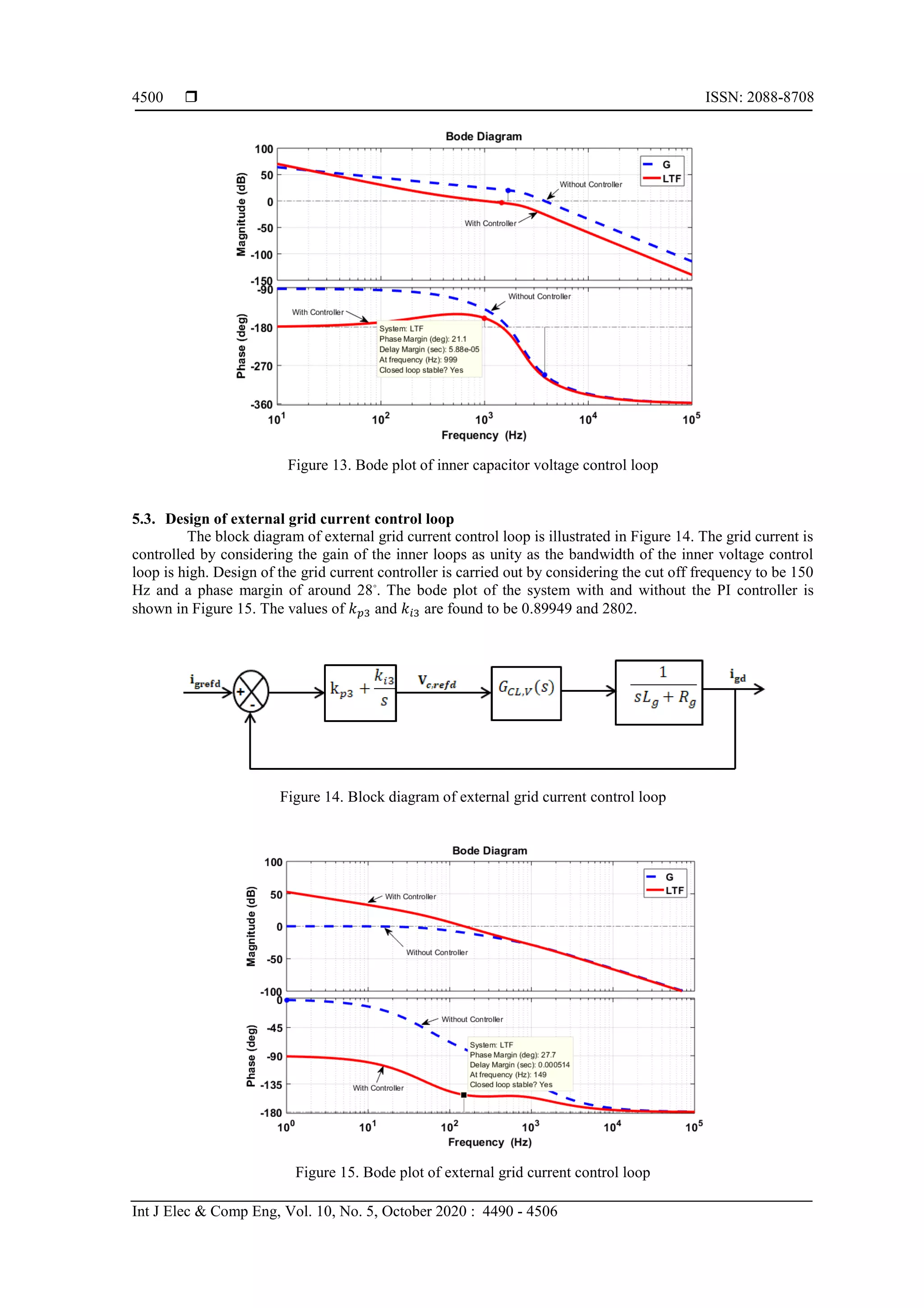
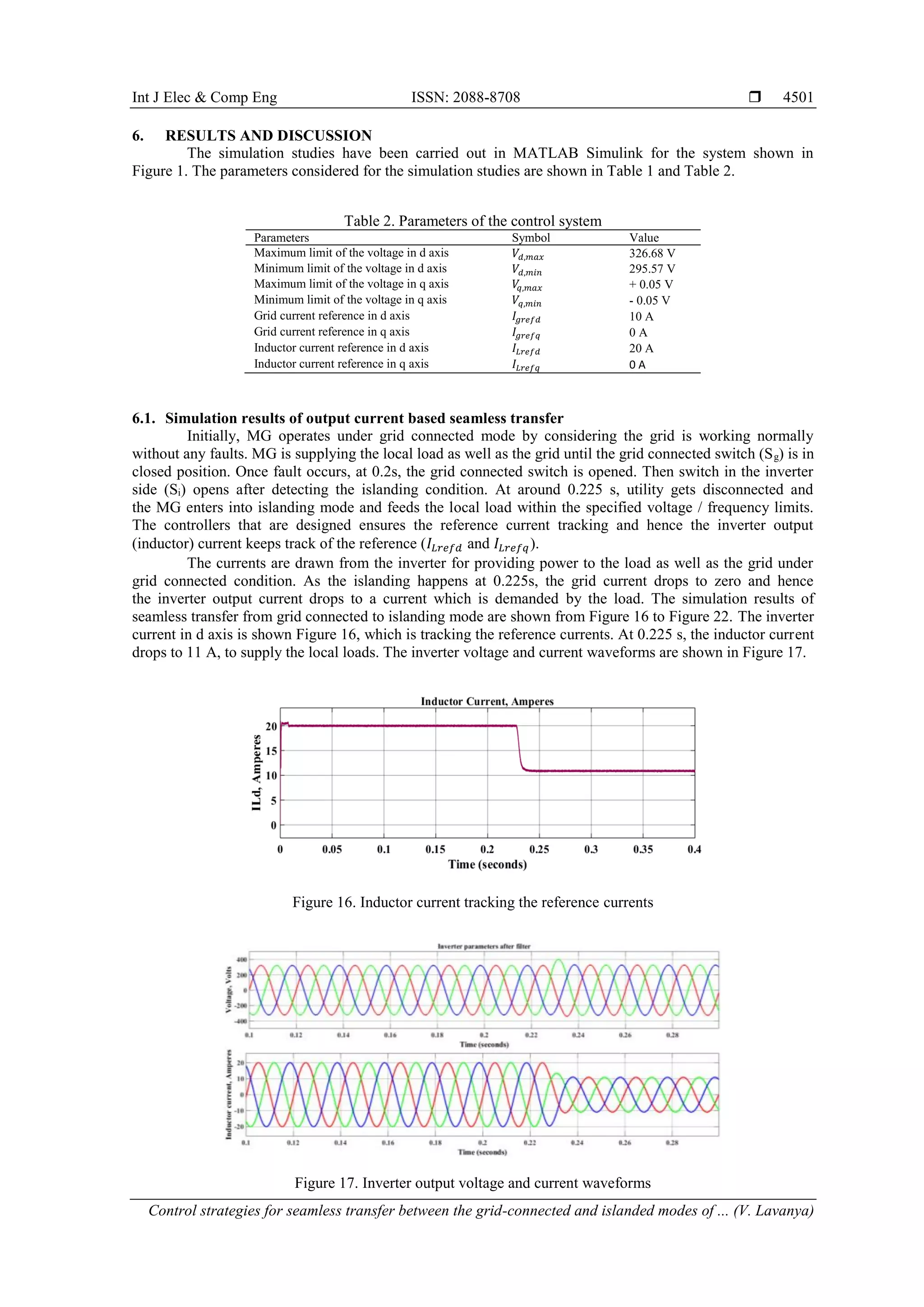
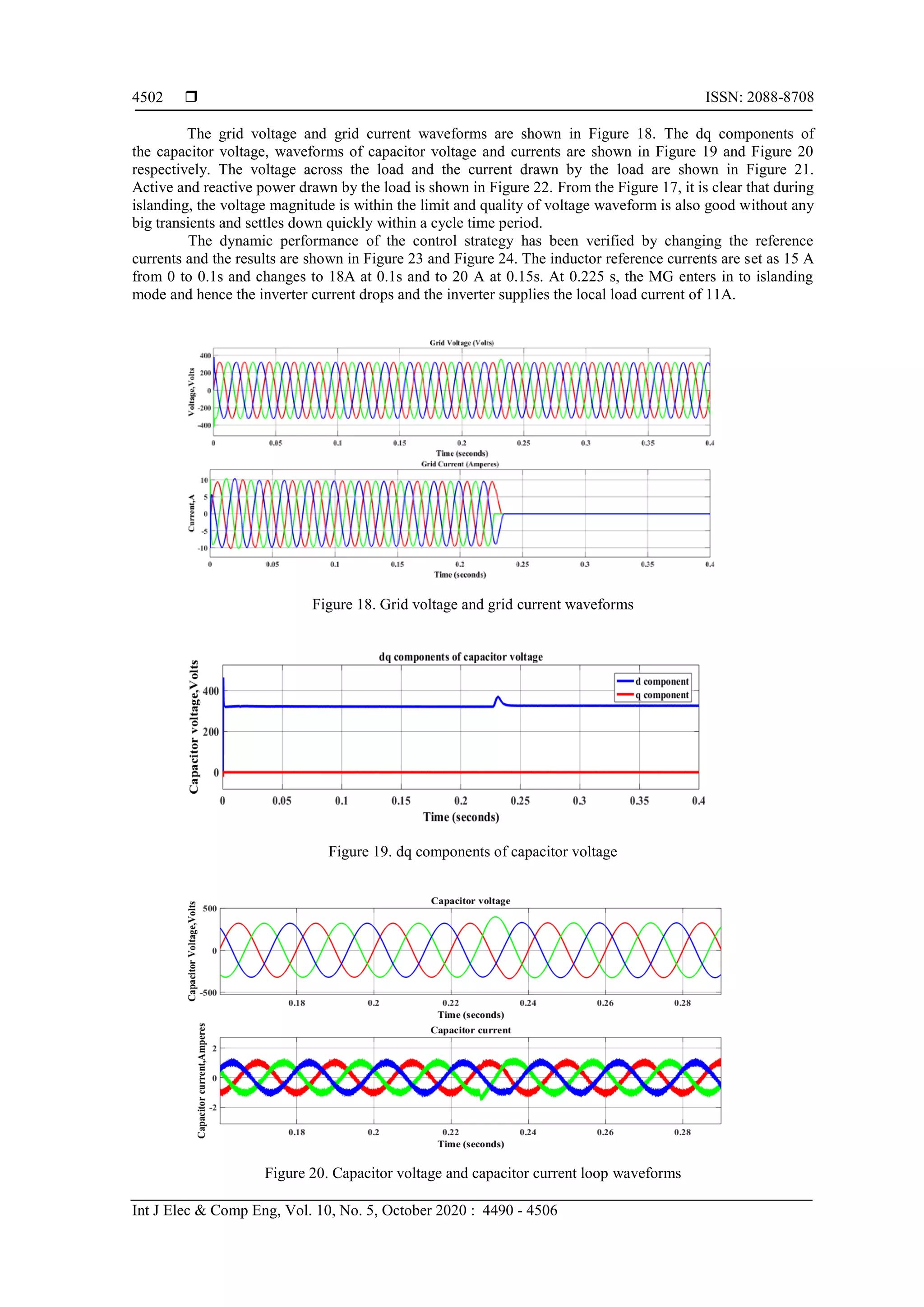
International Journal of Electrical and Computer Engineering (IJECE)
Vol. 10, No. 5, October 2020, pp. 4490~4506
ISSN: 2088-8708, DOI: 10.11591/ijece.v10i5.pp4490-4506  4490
Journal homepage: http://ijece.iaescore.com/index.php/IJECE
Control strategies for seamless transfer between
the grid-connected and islanded modes of a microgrid system
V. Lavanya, N. Senthil Kumar
School of Electrical Engineering, Vellore Institute of Technology, India
Article Info ABSTRACT
Article history:
Received Aug 19, 2019
Revised Mar 2, 2020
Accepted Mar 21, 2020
Design of control strategies for Distributed generation systems is very
important to achieve smoother transition between the grid connected and
islanding modes of operation. The transition between these two modes of
operation should be seamless, without any severe transients during
the changeover. In this paper, two different control strategies namely inverter
output current control and indirect grid current control for the seamless
transfer between the modes of operation has been explored for the suitability.
The design and analysis of the cascaded control loops based on Proportional
Integral (PI) controller has been dealt in detail for both inverter output
current control and indirect grid current control strategy. Control parameters
are designed using the control system toolbox in MATLAB. A 10kW grid
connected microgrid system has been designed and simulated in
MATLAB/Simulink and the results are presented under grid connected
operation, islanding operation and the transition between the modes
considering fault condition in the grid side. The simulation studies are carried
out using both the control strategies and the results are presented to validate
the design methodology.
Keywords:
Distributed generation
Grid-connected
Islanded
Microgrid
Seamless transfer
Three-phase inverter
Copyright © 2020 Institute of Advanced Engineering and Science.
All rights reserved.
Corresponding Author:
N. Senthil Kumar,
School of Electrical Engineering,
Vellore Institute of Technology,
Chennai, India.
Email: senthilkumarn.vit@gmail.com, senthilkumar.nataraj@vit.ac.in
1. INTRODUCTION
As the conventional energy resources are fast depleting and are of polluting nature, renewable
energy resources are being harnessed in meeting the ever increasing demands [1]. Recently, Distributed
Generators which are mainly based on the resources such as Wind, Solar PV, hydro, natural gas, biogas,
fuel cells etc., has gained lot of interest due to the increase in demand for the reliable and quality power [2].
Distributed Energy Resources (DER) can either be coupled straightaway to the distribution network at the
point of common coupling (PCC) or can be interconnected to form a Microgrid (MG) [3]. Power electronics
play a major role in integrating the renewable energy sources (RES) into the utility grid [4-6]. A microgrid is
a collection of energy sources which are of smaller capacity, energy storage schemes and a group of loads
which are being operated at distribution voltage levels [7]. Generally microgrids are associated with the main
grid at PCC and are operated as grid connected system. But under certain circumstances, microgrids can be
moved to the islanded mode of operation either intentionally or unintentionally [8]. The interfacing inverter is
to be controlled in such a manner that the microgrid works in asscociation with the main grid , independently
as islanded case when needed , and also while moving from one mode to other mode seamlessly [9-11].
In the case of grid connected operation, the interfacing power electronic converter is being
controlled so as to supply the main grid with the preset / stated power while the load voltage is being
maintained by the utility [12]. Under islanded mode, control of the inverter is mainly focussed to provide
Int J Elec & Comp Eng ISSN: 2088-8708 
Control strategies for seamless transfer between the grid-connected and islanded modes of ... (V. Lavanya)
4491
uninterrupted supply of electricity to the critical loads, with voltage and frequency within the stipulated
bounds [13].When the utility grid fails, because of any faults; the microgrid gets disconnected and operates in
autonomous mode. The islanding detection system detects the occurrence of faults in the utility side and
isolates the microgrid [14-16]. After the confirmation of islanding, the switch in the grid side is to be opened
and the load voltage is controlled by the inverter control system.
Hence, there will be a short duration in which the voltage across the load will not be the same as
the utility voltage or the microgrid system voltage maintained by the DG system and consequently the quality
of the voltage gets deprived under such circumstances [17]. Many control strategies have been proposed in
the literature for attaining smooth transition between the operating modes of microgrid [18-21]. The inverter
is controlled as a current source in grid connected mode for transferring power to the grid and as a voltage
source during islanding mode for maintaining voltage within the limits. Separate controllers are needed for
the two modes of operation and the switching between the control actions leads to poor voltage quality
especially during the transient process [22, 23].
For seamless transition between the modes, voltage source based droop controllers are employed [24].
Droop controllers that are implemented [25] for the power sharing among the DG systems that are connected
in parallel to feed the total connected load, leads to poor dynamics. A Master-slave control is another
common approach in microgrid where a Master unit i.e., the Voltage Source Inverter (VSI) which is being
controlled by PQ control structure for regulating the real and reactive power fed into the grid and under
islanding mode, the master unit is to be controlled as Voltage/frequency (V-f) control for maintaining
the voltage and frequency [26]. A novel control scheme has been developed in [27] which consist of
capacitor voltage controller as outer loop and inductor current controller as inner loop for improving
the voltage quality during the transition.
In another control scheme [28], the inverter output current is being controlled. The current fed to
the utility is regulated with the help of the filter inductor current control which in turn controls the capacitor
voltage and hence the microgrid voltage quality can be improved during the mode transition. In [17],
the current fed to the utility grid is regulated indirectly by having proper control of the voltage across
the filter capacitor. So among the existing inverter control techniques for achieving seamless transfer
between the modes and also to maintain the voltage that appears across the load during transition,
output current control and indirect current control or grid current control strategy has been preferred mostly.
In this paper, the design and analysis of two different control strategies namely, output current
control and indirect grid current control are explored for the suitability in grid connected microgrid system.
The cascaded control loops are designed based on Proportional Integral (PI) controller. Control parameters of
the control loops are designed using the control system toolbox in MATLAB. A 10kW grid connected
microgrid system has been designed and simulation studies are being carried out in MATLAB/Simulink
environment and the various simulation results under grid connected operation, islanding operation and
the transition between the modes, considering fault condition in the grid side are presented. The main
contribution of this paper is that, simulation studies have been carried out using both the control strategies
and the results are presented to validate the design methodology and the performances of the control
strategies are compared.
This paper deals with design, analysis and simulation studies of the control strategies for seamless
transfer in grid connected microgrid system. Section 2 presents the modelling of three phase inverter system.
Control strategies for seamless transfer are discussed in section 3. Sections 4 and 5 deals with the analysis
and design of control parameters for the control strategies discussed in section 3. Simulation results are
discussed in section 6. Section 7 proposes the conclusion.
2. MODELLING OF A THREE PHASE INVERTER SYSTEM
The power stage of a three phase inverter system is modelled based on synchronous reference frame
and the control strategies for the seamless transition using inverter output current control as well as
the indirect current control are presented.
2.1. Power stage of a three phase inverter in microgrid
The power stage of a three phase MG system is shown in Figure 1. The input side of the inverter is
considered as a stiff dc voltage. The energy sources can be of solar PV/ fuel cell or any renewable energy
sources. However the output voltages from these sources are very less and needs be boosted to the required
level with the help of the DC-DC converter. A voltage controller can be used to attain the desired dc link
voltage which is not dealt in this paper.
The output voltage from the three phase inverter is filtered with the help of LC filter consisting of
inductor Lf and the capacitor Cf. The filtered output is then connected to the local loads which may be
 ISSN: 2088-8708
Int J Elec & Comp Eng, Vol. 10, No. 5, October 2020 : 4490 - 4506
4492
critical/non-critical loads and it is coupled to the main grid via an inductor Lg called grid-side inductor.
The static transfer switch Si, present in the inverter side is being actuated by the inverter side controller and
the switch Sg present in the grid side is being actuated by the grid. Under normal working conditions of
the utility, both the switches Si and Sg are in the closed position and hence the three-phase DG inverter is
operated in the grid connected manner. In case of any faulty conditions or operations in the grid, the switch
Sg is opened which makes the DG system islanded.
Figure 1. Power stage of a three phase MG system
After the islanding detection, the inverter side switch Si is also opened and DG enters in to
standalone mode. Once the fault is cleared, the switch Sg is being closed. The DG side switch Si is closed to
make the system to be operated in association with the utility only after the resynchronization process
takes place.
2.2. Modelling of the power stage
The average mathematical model of a three phase inverter system is given by (1) and (2).
𝑉 𝑑𝑐
2
. (
𝑑 𝑎
𝑑 𝑏
𝑑 𝑐
) = 𝐿𝑓.
𝑑
𝑑𝑡
(
𝑖 𝐿𝑎
𝑖 𝐿𝑏
𝑖 𝐿𝑐
) + 𝑅𝑓. (
𝑖 𝐿𝑎
𝑖 𝐿𝑏
𝑖 𝐿𝑐
) + (
𝑣𝑐𝑎
𝑣 𝑐𝑏
𝑣𝑐𝑐
) (1)
(
𝑖 𝐿𝑎
𝑖 𝐿𝑏
𝑖 𝐿𝑐
) = 𝐶𝑓.
𝑑
𝑑𝑡
(
𝑣𝑐𝑎
𝑣 𝑐𝑏
𝑣𝑐𝑐
) + (
𝑖 𝐿𝐿𝑎
𝑖 𝐿𝐿𝑏
𝑖 𝐿𝐿𝑐
) + (
𝑖 𝑔𝑎
𝑖 𝑔𝑏
𝑖 𝑔𝑐
) (2)
In synchronous reference frame modelling, the equations governing the system shown in Figure 1
are given by (3) to (5).
𝑉 𝑑𝑐
2
. (
𝑑 𝑑
𝑑 𝑞
) = 𝐿𝑓.
𝑑
𝑑𝑡
(
𝑖 𝐿𝑑
𝑖 𝐿𝑞
) + (
0 −𝜔𝐿𝑓
𝜔𝐿𝑓 0
) . (
𝑖 𝐿𝑑
𝑖 𝐿𝑞
) + 𝑅𝑓. (
𝑖 𝐿𝑑
𝑖 𝐿𝑞
) + (
𝑣 𝐶𝑑
𝑣 𝐶𝑞
) (3)
(
𝑖 𝐿𝑑
𝑖 𝐿𝑞
) = 𝐶𝑓.
𝑑
𝑑𝑡
(
𝑣 𝐶𝑑
𝑣 𝐶𝑞
) + (
0 −𝜔𝐶𝑓
𝜔𝐶𝑓 0
) . (
𝑣 𝐶𝑑
𝑣 𝐶𝑞
) + (
𝑖 𝐿𝐿𝑑
𝑖 𝐿𝐿𝑞
) + (
𝑖 𝑔𝑑
𝑖 𝑔𝑞
) (4)
(
𝑣 𝐶𝑑
𝑣 𝐶𝑞
) = 𝐿 𝑔.
𝑑
𝑑𝑡
(
𝑖 𝑔𝑑
𝑖 𝑔𝑞
) + (
0 −𝜔𝐿 𝑔
𝜔𝐿 𝑔 0
) . (
𝑖 𝑔𝑑
𝑖 𝑔𝑞
) + 𝑅 𝑔 . (
𝑖 𝑔𝑑
𝑖 𝑔𝑞
) + (
𝑣 𝑔𝑑
𝑣𝑔𝑞
) (5)
Int J Elec & Comp Eng ISSN: 2088-8708 
Control strategies for seamless transfer between the grid-connected and islanded modes of ... (V. Lavanya)
4493
Where 𝑑 𝑑 and 𝑑 𝑞 are the duty cycles of three phase inverter system in synchronous reference frame,
𝑅𝑓 represents the resistance of filter inductor 𝐿𝑓, 𝑖 𝐿𝑑 and 𝑖 𝐿𝑞 represents the currents through the inductor 𝐿𝑓 ,
𝑖 𝐿𝐿𝑑 and 𝑖 𝐿𝐿𝑞 represents the load currents in ‘d q’ frames respectively and 𝑅 𝑔 indicates the resistance of
the grid side inductor 𝐿 𝑔. Figure 2 represents the block diagram of power stage modelling of MG system in
Synchronous reference frame (SRF).
Figure 2. Power stage model of the MG system in SRF
3. CONTROL STRATEGIES FOR THE SEAMLESS TRANSFER
3.1. Inverter output current based seamless transfer
The current fed to the grid can be regulated by controlling the inverter output current. The inductor
current 𝑖 𝐿,𝑎𝑏𝑐 and the capacitor voltage 𝑣 𝐶 ,𝑎𝑏𝑐 are sensed and are transformed to dq components using Park’s
transformation. The basic structural diagram of the output current control scheme is shown in Figure 3.
The control includes three loops viz., output current loop, inner voltage control loop, innermost inductor
current loop and a phase locked loop (PLL) for phase detection.
Figure 3. Control scheme based on output current control
 ISSN: 2088-8708
Int J Elec & Comp Eng, Vol. 10, No. 5, October 2020 : 4490 - 4506
4494
The output current controller is being realized with the help of a proportional-integral (PI)
controller. The output of the current controller generates the reference values for the capacitor (load voltage)
voltage loop i.e., vCrefd and vCrefq. A PI controller based inner voltage control loop regulates the capacitor
voltage vCd and vCq to follow the reference voltages generated by the outer loop. The innermost current
controller is mainly intended to maintain the required output current from the inverter which comprises of
the current that is to be fed to the utility as well as the current required by the load. Hence the grid current is
controlled with the help of inverter output current control. PLL used in the system is based on SRF to
measure the utility frequency and phase angle, which mainly includes a PI controller and a magnitude limiter
to maintain the frequency of the local load within the acceptable limits especially during islanding mode
of operation.
3.2. Indirect current control based seamless transfer
The structural diagram of the indirect grid current control scheme is shown in Figure 4. Seamless
transfer based on this control scheme involves grid current control by regulating the load voltage (capacitor
voltage) when operating under grid connected mode. Control scheme comprises of three control loops viz.,
outer grid current control loop, inner capacitor voltage loop and the innermost filter inductor current loop.
The outer grid current controller along with a limiter sets the reference voltage during the islanding
condition. Under grid connected condition, the voltage is going to be within the limits. The inner capacitor
voltage loop is a PI controller which generates the reference currents in d and q axis for the innermost filter
inductor current loop. The inductor current loop is a PI controller which produces the reference signal in dq
frame. The reference signal is transformed into ‘abc’ frame using dq-abc transformation and then given to
PWM generator for generating the firing pulses for the inverter switches.
Figure 4. Indirect grid current control scheme
When the main grid is working without any faults, the MG is treated as current source so as to feed
in the required active and reactive power to the grid. The reference currents in d and q axis can be calculated
based on the complex power that is to be fed to the grid. The grid current is controlled using a PI controller.
The coupling introduced due to the grid side inductor Lg is being attenuated by decoupling in the current
control loop. When any fault occurs in the grid side, the utility side switch, Sg opens and the MG is moving to
islanding mode of operation. The inverter switch Si is still in the closed position as the MG has to confirm
the occurrence of islanding. The switch Si opens, once the islanding is confirmed by the islanding detection
method. The active and reactive power injected into the grid is given by (6) and (7).
𝑃𝑔 =
3
2
. (𝑣 𝑔𝑑 𝑖 𝑔𝑑 + 𝑣𝑔𝑞 𝑖 𝑔𝑞) =
3
2
. 𝑣 𝑔𝑑 𝑖 𝑔𝑑 (6)
𝑄 𝑔 =
3
2
. (𝑣𝑔𝑞 𝑖 𝑔𝑑 − 𝑣 𝑔𝑑 𝑖 𝑔𝑞) = −
3
2
. 𝑣 𝑔𝑑 𝑖 𝑔𝑞 (7)
In islanding mode of operation, the switches Si and Sg are open and PLL cannot track the grid phase
angle. Under this condition, the MG is operated as a voltage source and therefore voltage fixed by the limiter
acts as the reference voltage. PLL consists of a PI controller and a limiter, which is used to regulate
the frequency within allowable limits.
Int J Elec & Comp Eng ISSN: 2088-8708 
Control strategies for seamless transfer between the grid-connected and islanded modes of ... (V. Lavanya)
4495
4. ANALYSIS AND DESIGN OF CONTROL PARAMETERS OF OUTPUT CURRENT BASED
SEAMLESS TRANSFER
4.1. Design of voltage magnitude limiter
The voltage limiter present in the Figure 3 and in Figure 4 is used to provide a stabilized voltage
without any deviation when the system gets transferred from grid connected mode to islanded mode. As per
the IEEE standard 1547_2018 [29], the voltage limiter in d and q axis can be represented by (8) and (9).
𝑣 𝑑,𝑚𝑎𝑥 = 1.1 ∗ √2 ∗ 𝑉𝑛𝑜𝑚𝑖𝑛𝑎𝑙 (8)
𝑣 𝑑,𝑚𝑖𝑛 = 0.9 ∗ √2 ∗ 𝑉𝑛𝑜𝑚𝑖𝑛𝑎𝑙 (9)
where, 𝑣 𝑑,𝑚𝑎𝑥 and 𝑣 𝑑,𝑚𝑖𝑛 represents the maximum and minimum values of the voltage magnitude in
the d axis, 𝑉𝑛𝑜𝑚𝑖𝑛𝑎𝑙 is the nominal per phase grid voltage. When the MG transfers from grid connected mode
to islanded mode, the voltage limiter in the q axis is to be designed based on (10) and (11), so that the load
voltage is within the normal range.
𝑣𝑞,𝑚𝑎𝑥 = +𝜀 (10)
𝑣 𝑞,𝑚𝑖𝑛 = − 𝜀 (11)
where, 𝑣𝑞,𝑚𝑎𝑥 and 𝑣 𝑞,𝑚𝑖𝑛 represents the maximum and minimum values of voltage in q axis.
4.2. Design of frequency / phase limiter
The frequency and phase of the grid voltage can be obtained with the synchronous reference frame
based PLL, when the MG system is operating in grid connected mode. When the fault occurs in the grid side,
the frequency and phase may get deviated. In order to limit the deviations beyond a level, a limiter is being
introduced to restrict the frequency and phase deviations during islanding. The basic block diagram of
SRF-PLL is shown in Figure 5.
Figure 5. Block diagram of SRF-PLL
4.3. Design of filter and control loops
The specification of the parameters used in the DG system considered is given in Table 1. The filter
and the control loop parameters are designed based on the DG specifications.
Table 1. Parameters of the MG system
Parameters Symbol Value
DC link voltage 𝑉𝑑𝑐 700 V
Filter inductor 𝐿 𝑓 3.11 mH
Resistance of filter inductor 𝑅𝑓 1 Ω
Filter capacitor 𝐶𝑓 10 µF
Switching frequency 𝑓𝑠 20 kHz
Grid side inductor 𝐿 𝑔 3.11 mH
Resistance of grid side inductor 𝑅 𝑔 1 Ω
Grid frequency 𝑓𝑔 50 Hz
Grid voltage 𝑉𝑔 220 V(rms)
Rated power of DG 𝑃𝐷𝐺 10 kW
Power rating of Load 𝑃𝐿 5 kW
 ISSN: 2088-8708
Int J Elec & Comp Eng, Vol. 10, No. 5, October 2020 : 4490 - 4506
4496
4.3.1. Design of LCL filter
The output from the three phase inverter is filtered with the help of LCL filter [30] to suppress
the harmonics introduced due to the presence of power electronic interface. The base impedance and the base
capacitance are obtained based on the (12) and (13).
𝑍 𝑏𝑎𝑠𝑒 =
𝑉𝐿−𝐿
2
𝑃 𝑛𝑜𝑚𝑖𝑛𝑎𝑙
(12)
𝐶 𝑏𝑎𝑠𝑒 =
1
𝜔 𝑔 𝑍 𝑏𝑎𝑠𝑒
(13)
As the maximum power factor variation seen by the grid is 5%, the filter capacitance can be
designed based on (14).
𝐶𝑓 = 0.05 ∗ 𝐶 𝑏𝑎𝑠𝑒 (14)
The maximum ripple allowable can be considered as 10% of the maximum rated current and the
ripple is given by (15),
∆𝐼 𝑚𝑎𝑥 = 10% ∗ 𝐼 𝑚𝑎𝑥 (15)
where 𝐼 𝑚𝑎𝑥 is given by (16).
𝐼 𝑚𝑎𝑥 =
√2𝑃 𝑛𝑜𝑚𝑖𝑛𝑎𝑙
3 𝑉 𝑝ℎ
(16)
The inverter side filter inductor, 𝐿𝑓 is given by (17) and the grid side inductor, 𝐿 𝑔is given by (18),
𝐿𝑓 =
𝑉 𝑑𝑐
16 𝑓𝑠 ∆𝐼 𝑚𝑎𝑥
(17)
𝐿 𝑔 = 𝑟 𝐿𝑓 (18)
where, 𝑉𝑑𝑐 represents dc link voltage, 𝑓𝑠 , the switching frequency of the inverter switches and r is the ratio
between 𝐿𝑓 and 𝐿 𝑔 and the value of r is to be considered based on the nominal grid impedance and
the resonant frequency from the transfer function of the filter. The resonant frequency and the frequency
constraint are given by (19) and (20).
𝜔𝑟𝑒𝑠 = √
𝐿 𝑓+ 𝐿 𝑔
𝐿 𝑓 𝐿 𝑔 𝐶 𝑓
(19)
10 𝑓𝑔 < 𝑓𝑟𝑒𝑠 < 0.5 𝑓𝑠 (20)
4.3.2. Design of innermost inductor current control loop
Figure 6 represents the basic structure of the innermost inductor current control loop.
Figure 6. Control structure of inductor current control loop
Int J Elec & Comp Eng ISSN: 2088-8708 
Control strategies for seamless transfer between the grid-connected and islanded modes of ... (V. Lavanya)
4497
From the Figure 6, the open loop transfer function of current control loop is given by (21).
𝐺 𝑂𝐿,𝐼𝐶(𝑠) =
𝐾 𝑃𝑊𝑀 (𝑘 𝑝1+
𝑘 𝑖1
𝑠
)
(1+1.5 𝑠 𝑇𝑠)(𝑠𝐿 𝑓+𝑅 𝑓)
(21)
Where, the digital delay is considered to be of 1.5 times the switching period Ts, 𝐾𝑃𝑊𝑀 is the gain of
the converter and is considered as 1 for simplicity. The controllers are designed in MATLAB using control
system designer tool box. The bode diagram of the innermost inductor current loop with and without PI
controller is shown in Figure 7, where G represents Transfer function without controller and LTF represents
Loop transfer function with PI controller. The controller is designed to attain cut off frequency of around
1200 Hz and phase margin of 60⸰
. The 𝑘 𝑝1 and 𝑘𝑖1 values of the PI controller are about 27.014 and 8371.
Figure 7. Bode plot of innermost inductor current control loop
4.3.3. Design of inner capacitor voltage control loop
The basic structural diagram of capacitor voltage control loop is presented in Figure 8. From
the Figure 8, the open loop transfer function of the voltage control loop is given by (22).
𝐺 𝑂𝐿,𝑉(𝑠) =
(𝑘 𝑝2+
𝑘 𝑖2
𝑠
) 𝐺 𝐶𝐿.𝐼𝐶(𝑠)
(1+1.5 𝑠 𝑇𝑠)(𝑠𝐶 𝑓)
(22)
Where, the digital delay is considered to be of 1.5 times the switching period Ts and 𝐺 𝐶𝐿.𝐼𝐶(𝑠) is the closed
loop transfer function of the innermost inductor current loop.
Figure 8. Control structure of capacitor voltage control loop
 ISSN: 2088-8708
Int J Elec & Comp Eng, Vol. 10, No. 5, October 2020 : 4490 - 4506
4498
The bode plot of the voltage control loop with and without PI controller is shown in Figure 9.
The controller is designed to attain cut off frequency of around 800 Hz and phase margin of 45⸰
. The 𝑘 𝑝2 and
𝑘𝑖2 values of the PI controller are about 0.063207 and 38.755.
Figure 9. Bode plot of inner capacitor voltage control loop
4.3.4. Design of outer current control loop
The block diagram of outer current controller is given in Figure 10.
Figure 10. Control structure of outer current control loop
From the Figure 10, the open loop transfer function of the outer current control loop is
given by (23).
𝐺 𝑂𝐿,𝑂𝐶(𝑠) = (𝑘 𝑝3 +
𝑘 𝑖3
𝑠
) 𝐺 𝐶𝐿,𝑉(𝑠) 𝑠 𝐶𝑓 (23)
where, 𝐺 𝐶𝐿,𝑉(𝑠) is the closed loop transfer function of the voltage control loop. The bode plot of the open
loop transfer function of outer current control loop with and without controller is shown in Figure 11.
The values of 𝑘 𝑝3 and 𝑘𝑖3 are found to be 0.25504 and 142570.
Int J Elec & Comp Eng ISSN: 2088-8708 
Control strategies for seamless transfer between the grid-connected and islanded modes of ... (V. Lavanya)
4499
Figure 11. Bode plot of outer current control loop
5. ANALYSIS AND DESIGN OF CONTROL PARAMETERS OF INDIRECT CURRENT
CONTROL BASED SEAMLESS TRANSFER
5.1. Design of innermost inductor current control loop
The block diagram of innermost inductor current loop is same as shown in Figure 6. The innermost
inductor current loop is designed using control system designer tool box in MATLAB by considering a cut
off frequency of 2000 Hz with a phase margin of around 41⸰
. The bode plot of the system with and without
the PI controller is shown in Figure 12. The 𝑘 𝑝1 and 𝑘𝑖1 values of the PI controller are about 52.574
and 87583.
Figure 12. Bode plot of innermost inductor current control loop
5.2. Design of inner capacitor voltage control loop
The block diagram of inner capacitor voltage loop is same as that shown in Figure 8. The voltage
loop is designed by considering a cut off frequency of 1000 Hz with a phase margin of around 21⸰
. The bode
plot of the system with and without the PI controller is shown in Figure 13. The 𝑘 𝑝2 and 𝑘𝑖2 values of the PI
controller are about 0.053285 and 128.83.
 ISSN: 2088-8708
Int J Elec & Comp Eng, Vol. 10, No. 5, October 2020 : 4490 - 4506
4500
Figure 13. Bode plot of inner capacitor voltage control loop
5.3. Design of external grid current control loop
The block diagram of external grid current control loop is illustrated in Figure 14. The grid current is
controlled by considering the gain of the inner loops as unity as the bandwidth of the inner voltage control
loop is high. Design of the grid current controller is carried out by considering the cut off frequency to be 150
Hz and a phase margin of around 28⸰
. The bode plot of the system with and without the PI controller is
shown in Figure 15. The values of 𝑘 𝑝3 and 𝑘𝑖3 are found to be 0.89949 and 2802.
Figure 14. Block diagram of external grid current control loop
Figure 15. Bode plot of external grid current control loop
Int J Elec & Comp Eng ISSN: 2088-8708 
Control strategies for seamless transfer between the grid-connected and islanded modes of ... (V. Lavanya)
4501
6. RESULTS AND DISCUSSION
The simulation studies have been carried out in MATLAB Simulink for the system shown in
Figure 1. The parameters considered for the simulation studies are shown in Table 1 and Table 2.
Table 2. Parameters of the control system
Parameters Symbol Value
Maximum limit of the voltage in d axis 𝑉𝑑,𝑚𝑎𝑥 326.68 V
Minimum limit of the voltage in d axis 𝑉𝑑,𝑚𝑖𝑛 295.57 V
Maximum limit of the voltage in q axis 𝑉𝑞,𝑚𝑎𝑥 + 0.05 V
Minimum limit of the voltage in q axis 𝑉𝑞,𝑚𝑖𝑛 - 0.05 V
Grid current reference in d axis 𝐼𝑔𝑟𝑒𝑓𝑑 10 A
Grid current reference in q axis 𝐼𝑔𝑟𝑒𝑓𝑞 0 A
Inductor current reference in d axis 𝐼𝐿𝑟𝑒𝑓𝑑 20 A
Inductor current reference in q axis 𝐼𝐿𝑟𝑒𝑓𝑞 0 A
6.1. Simulation results of output current based seamless transfer
Initially, MG operates under grid connected mode by considering the grid is working normally
without any faults. MG is supplying the local load as well as the grid until the grid connected switch (Sg) is in
closed position. Once fault occurs, at 0.2s, the grid connected switch is opened. Then switch in the inverter
side (Si) opens after detecting the islanding condition. At around 0.225 s, utility gets disconnected and
the MG enters into islanding mode and feeds the local load within the specified voltage / frequency limits.
The controllers that are designed ensures the reference current tracking and hence the inverter output
(inductor) current keeps track of the reference (𝐼𝐿𝑟𝑒𝑓𝑑 and 𝐼𝐿𝑟𝑒𝑓𝑞).
The currents are drawn from the inverter for providing power to the load as well as the grid under
grid connected condition. As the islanding happens at 0.225s, the grid current drops to zero and hence
the inverter output current drops to a current which is demanded by the load. The simulation results of
seamless transfer from grid connected to islanding mode are shown from Figure 16 to Figure 22. The inverter
current in d axis is shown Figure 16, which is tracking the reference currents. At 0.225 s, the inductor current
drops to 11 A, to supply the local loads. The inverter voltage and current waveforms are shown in Figure 17.
Figure 16. Inductor current tracking the reference currents
Figure 17. Inverter output voltage and current waveforms
 ISSN: 2088-8708
Int J Elec & Comp Eng, Vol. 10, No. 5, October 2020 : 4490 - 4506
4502
The grid voltage and grid current waveforms are shown in Figure 18. The dq components of
the capacitor voltage, waveforms of capacitor voltage and currents are shown in Figure 19 and Figure 20
respectively. The voltage across the load and the current drawn by the load are shown in Figure 21.
Active and reactive power drawn by the load is shown in Figure 22. From the Figure 17, it is clear that during
islanding, the voltage magnitude is within the limit and quality of voltage waveform is also good without any
big transients and settles down quickly within a cycle time period.
The dynamic performance of the control strategy has been verified by changing the reference
currents and the results are shown in Figure 23 and Figure 24. The inductor reference currents are set as 15 A
from 0 to 0.1s and changes to 18A at 0.1s and to 20 A at 0.15s. At 0.225 s, the MG enters in to islanding
mode and hence the inverter current drops and the inverter supplies the local load current of 11A.
Figure 18. Grid voltage and grid current waveforms
Figure 19. dq components of capacitor voltage
Figure 20. Capacitor voltage and capacitor current loop waveforms
Int J Elec & Comp Eng ISSN: 2088-8708 
Control strategies for seamless transfer between the grid-connected and islanded modes of ... (V. Lavanya)
4503
Figure 21. Load voltage and load current waveforms
Figure 22. Active and reactive power of the local resistive load
Figure 23. Inductor current under varying reference values
Figure 24. Inverter output voltage and current waveforms under varying reference currents
 ISSN: 2088-8708
Int J Elec & Comp Eng, Vol. 10, No. 5, October 2020 : 4490 - 4506
4504
6.2. Simulation results of indirect grid current control based seamless transfer
Simulation studies have been carried out by considering that the system is initially grid connected
and supplying power to the local load as well as feeding power to the utility grid. MG is moving to islanded
mode when fault occurs in the grid side. The parameters of the system under study are same as shown in
Table 1 and Table 2. At 0.35s fault occurs in the grid side and hence the grid connected system changes to
standalone mode. The grid current reference considered is 10 A and the results are shown in Figure 25 to
Figure 30. The tracking of the grid reference current is shown in Figure 25.
Comparing the results of the control strategies, the output current control strategy gives better
dynamic response. From Figure 23 and Figure 25, it is very clear that the output current control strategy
tracks the reference current faster within half cycle and without any transients whereas in the grid current
control, transients takes place when the reference changes and also it takes around 2 to 3 cycles to settle
down to the reference value.
Figure 25. Grid current (Igd) reference tracking
Figure 26. Inverter voltage and current waveforms
Figure 27. Grid voltage and grid current waveforms
Int J Elec & Comp Eng ISSN: 2088-8708 
Control strategies for seamless transfer between the grid-connected and islanded modes of ... (V. Lavanya)
4505
Figure 28. dq components of Capacitor voltage and current waveforms
Figure 29. Capacitor voltage and current waveforms
Figure 30. Load voltage and load current waveforms
7. CONCLUSION
This paper discusses about the control strategies for attaining seamless transfer between the grid
connected and islanding modes of operation of a Microgrid system. Simulation studies have been carried out
using both indirect current control strategy and output current control strategy for a grid connected microgrid
system to achieve seamless transfer. The Simulation results demonstrate that the smooth transition is
achieved from grid connected to islanding mode when the switch in the grid side is opened under faulty
conditions. The design of control loop is also validated from the simulation results by considering the settling
time and steady state error as the performance parameters. Simulation results demonstrate that when
the changeover takes from grid connected to islanded mode, the transients in load voltage, inverter output
current settle within 10ms.
 ISSN: 2088-8708
Int J Elec & Comp Eng, Vol. 10, No. 5, October 2020 : 4490 - 4506
4506
REFERENCES
[1] S. Chowdhury, et al., “Microgrids and active distribution networks,” IET Renewable Energy Series, vol. 6, 2009.
[2] N. Hatziargyriou, et al., “Microgrids,” IEEE Power and Energy Magazine, vol. 5, no. 4, pp. 78-94, 2007.
[3] J. Driesen and F. Katiraei, “Design for distributed energy resources,” IEEE Power and Energy Magazine, vol. 6,
no. 3, pp. 30-40, 2008.
[4] F. Blaabjerg, et al., “Power electronics as efficient interface in dispersed power generation systems,” IEEE
Transactions on Power Electronics, vol. 19, no. 5, pp. 1184-1194, 2004.
[5] A. Kahrobaeian and Y. A. I. Mohamed, “Interactive distributed generation interface for flexible micro-grid
operation in smart distribution systems,” IEEE Transactions on Sustainable Energy, vol. 3, no. 2, pp. 295-305,
2012.
[6] J. M. Carrasco, et al., “Power-electronic systems for the grid integration of renewable energy sources: A survey,”
IEEE Transactions on Industrial Electronics, vol. 53, no. 4, pp. 1002-1016, 2006.
[7] R. H. Lasseter, “Microgrids,” in 2002 IEEE Power Engineering Society Winter Meeting Conference Proceedings,
New York, vol. 1, pp. 305-308, 2002.
[8] I. Alhamrouni, et al., “Modelling of micro-grid with the consideration of total harmonic distortion analysis,”
Indonesian Journal of Electrical Engineering and Computer Science, vol. 15, no. 2, pp. 581-592, 2019.
[9] F. Katiraei, et al., “Microgrids management,” IEEE Power and Energy Magazine, vol. 6, no. 3, pp. 54-65, 2008.
[10] N. Pogaku, et al., “Modeling, analysis and testing of autonomous operation of an inverter-based microgrid,” IEEE
Transactions on Power Electronics, vol. 22, no. 2, pp. 613-625, 2007.
[11] M. A. Hossain, et al., “Overview of AC microgrid controls with inverter-interfaced generations,” Energies, vol. 10,
no. 9, pp. 1300, 2017.
[12] P. Basak, et al., “A literature review on integration of distributed energy resources in the perspective of control,
protection and stability of microgrid,” Renewable and Sustainable Energy Reviews, vol. 16, no. 8, pp. 5545-5556,
2012.
[13] T. L. Vandoorn, et al., “Review of primary control strategies for islanded microgrids with power-electronic
interfaces,” Renewable and Sustainable Energy Reviews, vol. 19, pp. 613-628, 2013.
[14] A. M. Massoud, et al., “Harmonic distortion-based island detection technique for inverter-based distributed
generation,” IET Renewable Power Generation, vol. 3, no. 4, pp. 493-507, 2009.
[15] R. Chilakala, et al., “A passive islanding detection method for hybrid distributed generation system under balanced
islanding,” Indonesian Journal of Electrical Engineering and Computer Science, vol. 14, no. 1, pp. 9-19, 2019.
[16] F. Ghalavand, et al., “Microgrid islanding detection based on mathematical morphology,” Energies, vol. 11,
no. 10, pp. 2696, 2018.
[17] Z. Liu and J. Liu, “Indirect Current Control Based Seamless Transfer of Three-phase Inverter in Distributed
Generation,” IEEE Transactions on Power Electronics, vol. 29, no. 7, pp. 3368-3383, 2014.
[18] T. S. Tran, et al., “The analysis of technical trend in islanding operation, haramonic distortion, stabilizing frequency
and voltage of islanded entities,” Resources, vol. 8, pp. 14-41, 2019.
[19] Y. A. I. Mohamed and A. A. Radwan, “Hierarchical control system for robust microgrid operation and seamless
mode transfer in active distribution systems,” IEEE Transactions on Smart grid, vol. 2, no. 2, pp. 352-362, 2011.
[20] F. Tang, et al., “Distributed active Synchronization strategy for microgrid seamless reconnection to the grid under
unbalance and harmonic distortion,” IEEE Transactions on Smart grid, vol. 6, no. 6, pp. 2757-2769, 2015.
[21] S. Yoon, et al., “Controller design and implementation of indirect current control based utility –interactive inverters
system,” in Proceedings 3rd
IEEE Energy Conversion Congress Exposition, Phoenix, USA, pp. 955-960, 2011.
[22] I. J. Balaguer, et al., “Control for grid- connected and intentional islanding operations of distributed power
generation,” IEEE Transactions on Industrial Electronics, vol. 58, no. 1, pp. 147-157, 2011.
[23] D. N. Goankar, et al., “Seamless transfer of micro-turbine generation system operation between grid-connected and
islanding modes,” Electrical Power Components and Systems, vol. 37, no. 2, pp. 174-188, 2009.
[24] T. L. Vandoorn, et al., “Transition from islanded to grid-connected mode of microgrids with voltage-based droop
control,” IEEE Transactions on Power systems, vol. 28, no. 3, pp. 2545-2553, 2013.
[25] J. M. Gurrerro, et al., “Control of distributed uninterruptible power supply systems,” IEEE Transactions on
Industrial Electronics, vol. 55, no. 8, pp. 2845-2859, 2008.
[26] X. Meng, et al., “A seamless transfer strategy based on indirect current control and droop control,” IEEE 3rd
International Future Energy Electronics Conference and ECCE Asia, pp. 1611-1616, 2017.
[27] I. Ahmed, et al., “A Novel Control scheme for microgrid inverters seamless transferring between Grid-connected
and islanding mode,” China International Electrical and Energy Conference (CIEEC), pp. 75-80, 2017.
[28] Y. Wang and G. Zhao, “An Output Current based Seamless Transfer Control Strategy for Three-Phase Converter
with Energy Storage in Microgrid,” International Conference on Renewable Power Generation (RPG 2015),
Beijing, China, pp. 1-6, 2015.
[29] IEEE Standards Association, “IEEE Standard for Interconnection and Interoperability of Distributed Energy
Resources with Associated Electric Power Systems Interfaces,” IEEE Std 1547™-2018, pp. 1-138, 2018.
[30] Z. A. Ovano and C. Ambrish, “Simulation and stability analysis of a 100 kW grid connected LCL photovoltaic
inverter for industry,” IEEE Power Engineering Society General Meeting, Montreal, Que, pp. 6, 2006.

Control strategies for seamless transfer between the grid-connected and islanded modes of a microgrid system

  • 1.
    International Journal ofElectrical and Computer Engineering (IJECE) Vol. 10, No. 5, October 2020, pp. 4490~4506 ISSN: 2088-8708, DOI: 10.11591/ijece.v10i5.pp4490-4506  4490 Journal homepage: http://ijece.iaescore.com/index.php/IJECE Control strategies for seamless transfer between the grid-connected and islanded modes of a microgrid system V. Lavanya, N. Senthil Kumar School of Electrical Engineering, Vellore Institute of Technology, India Article Info ABSTRACT Article history: Received Aug 19, 2019 Revised Mar 2, 2020 Accepted Mar 21, 2020 Design of control strategies for Distributed generation systems is very important to achieve smoother transition between the grid connected and islanding modes of operation. The transition between these two modes of operation should be seamless, without any severe transients during the changeover. In this paper, two different control strategies namely inverter output current control and indirect grid current control for the seamless transfer between the modes of operation has been explored for the suitability. The design and analysis of the cascaded control loops based on Proportional Integral (PI) controller has been dealt in detail for both inverter output current control and indirect grid current control strategy. Control parameters are designed using the control system toolbox in MATLAB. A 10kW grid connected microgrid system has been designed and simulated in MATLAB/Simulink and the results are presented under grid connected operation, islanding operation and the transition between the modes considering fault condition in the grid side. The simulation studies are carried out using both the control strategies and the results are presented to validate the design methodology. Keywords: Distributed generation Grid-connected Islanded Microgrid Seamless transfer Three-phase inverter Copyright © 2020 Institute of Advanced Engineering and Science. All rights reserved. Corresponding Author: N. Senthil Kumar, School of Electrical Engineering, Vellore Institute of Technology, Chennai, India. Email: senthilkumarn.vit@gmail.com, senthilkumar.nataraj@vit.ac.in 1. INTRODUCTION As the conventional energy resources are fast depleting and are of polluting nature, renewable energy resources are being harnessed in meeting the ever increasing demands [1]. Recently, Distributed Generators which are mainly based on the resources such as Wind, Solar PV, hydro, natural gas, biogas, fuel cells etc., has gained lot of interest due to the increase in demand for the reliable and quality power [2]. Distributed Energy Resources (DER) can either be coupled straightaway to the distribution network at the point of common coupling (PCC) or can be interconnected to form a Microgrid (MG) [3]. Power electronics play a major role in integrating the renewable energy sources (RES) into the utility grid [4-6]. A microgrid is a collection of energy sources which are of smaller capacity, energy storage schemes and a group of loads which are being operated at distribution voltage levels [7]. Generally microgrids are associated with the main grid at PCC and are operated as grid connected system. But under certain circumstances, microgrids can be moved to the islanded mode of operation either intentionally or unintentionally [8]. The interfacing inverter is to be controlled in such a manner that the microgrid works in asscociation with the main grid , independently as islanded case when needed , and also while moving from one mode to other mode seamlessly [9-11]. In the case of grid connected operation, the interfacing power electronic converter is being controlled so as to supply the main grid with the preset / stated power while the load voltage is being maintained by the utility [12]. Under islanded mode, control of the inverter is mainly focussed to provide
  • 2.
    Int J Elec& Comp Eng ISSN: 2088-8708  Control strategies for seamless transfer between the grid-connected and islanded modes of ... (V. Lavanya) 4491 uninterrupted supply of electricity to the critical loads, with voltage and frequency within the stipulated bounds [13].When the utility grid fails, because of any faults; the microgrid gets disconnected and operates in autonomous mode. The islanding detection system detects the occurrence of faults in the utility side and isolates the microgrid [14-16]. After the confirmation of islanding, the switch in the grid side is to be opened and the load voltage is controlled by the inverter control system. Hence, there will be a short duration in which the voltage across the load will not be the same as the utility voltage or the microgrid system voltage maintained by the DG system and consequently the quality of the voltage gets deprived under such circumstances [17]. Many control strategies have been proposed in the literature for attaining smooth transition between the operating modes of microgrid [18-21]. The inverter is controlled as a current source in grid connected mode for transferring power to the grid and as a voltage source during islanding mode for maintaining voltage within the limits. Separate controllers are needed for the two modes of operation and the switching between the control actions leads to poor voltage quality especially during the transient process [22, 23]. For seamless transition between the modes, voltage source based droop controllers are employed [24]. Droop controllers that are implemented [25] for the power sharing among the DG systems that are connected in parallel to feed the total connected load, leads to poor dynamics. A Master-slave control is another common approach in microgrid where a Master unit i.e., the Voltage Source Inverter (VSI) which is being controlled by PQ control structure for regulating the real and reactive power fed into the grid and under islanding mode, the master unit is to be controlled as Voltage/frequency (V-f) control for maintaining the voltage and frequency [26]. A novel control scheme has been developed in [27] which consist of capacitor voltage controller as outer loop and inductor current controller as inner loop for improving the voltage quality during the transition. In another control scheme [28], the inverter output current is being controlled. The current fed to the utility is regulated with the help of the filter inductor current control which in turn controls the capacitor voltage and hence the microgrid voltage quality can be improved during the mode transition. In [17], the current fed to the utility grid is regulated indirectly by having proper control of the voltage across the filter capacitor. So among the existing inverter control techniques for achieving seamless transfer between the modes and also to maintain the voltage that appears across the load during transition, output current control and indirect current control or grid current control strategy has been preferred mostly. In this paper, the design and analysis of two different control strategies namely, output current control and indirect grid current control are explored for the suitability in grid connected microgrid system. The cascaded control loops are designed based on Proportional Integral (PI) controller. Control parameters of the control loops are designed using the control system toolbox in MATLAB. A 10kW grid connected microgrid system has been designed and simulation studies are being carried out in MATLAB/Simulink environment and the various simulation results under grid connected operation, islanding operation and the transition between the modes, considering fault condition in the grid side are presented. The main contribution of this paper is that, simulation studies have been carried out using both the control strategies and the results are presented to validate the design methodology and the performances of the control strategies are compared. This paper deals with design, analysis and simulation studies of the control strategies for seamless transfer in grid connected microgrid system. Section 2 presents the modelling of three phase inverter system. Control strategies for seamless transfer are discussed in section 3. Sections 4 and 5 deals with the analysis and design of control parameters for the control strategies discussed in section 3. Simulation results are discussed in section 6. Section 7 proposes the conclusion. 2. MODELLING OF A THREE PHASE INVERTER SYSTEM The power stage of a three phase inverter system is modelled based on synchronous reference frame and the control strategies for the seamless transition using inverter output current control as well as the indirect current control are presented. 2.1. Power stage of a three phase inverter in microgrid The power stage of a three phase MG system is shown in Figure 1. The input side of the inverter is considered as a stiff dc voltage. The energy sources can be of solar PV/ fuel cell or any renewable energy sources. However the output voltages from these sources are very less and needs be boosted to the required level with the help of the DC-DC converter. A voltage controller can be used to attain the desired dc link voltage which is not dealt in this paper. The output voltage from the three phase inverter is filtered with the help of LC filter consisting of inductor Lf and the capacitor Cf. The filtered output is then connected to the local loads which may be
  • 3.
     ISSN: 2088-8708 IntJ Elec & Comp Eng, Vol. 10, No. 5, October 2020 : 4490 - 4506 4492 critical/non-critical loads and it is coupled to the main grid via an inductor Lg called grid-side inductor. The static transfer switch Si, present in the inverter side is being actuated by the inverter side controller and the switch Sg present in the grid side is being actuated by the grid. Under normal working conditions of the utility, both the switches Si and Sg are in the closed position and hence the three-phase DG inverter is operated in the grid connected manner. In case of any faulty conditions or operations in the grid, the switch Sg is opened which makes the DG system islanded. Figure 1. Power stage of a three phase MG system After the islanding detection, the inverter side switch Si is also opened and DG enters in to standalone mode. Once the fault is cleared, the switch Sg is being closed. The DG side switch Si is closed to make the system to be operated in association with the utility only after the resynchronization process takes place. 2.2. Modelling of the power stage The average mathematical model of a three phase inverter system is given by (1) and (2). 𝑉 𝑑𝑐 2 . ( 𝑑 𝑎 𝑑 𝑏 𝑑 𝑐 ) = 𝐿𝑓. 𝑑 𝑑𝑡 ( 𝑖 𝐿𝑎 𝑖 𝐿𝑏 𝑖 𝐿𝑐 ) + 𝑅𝑓. ( 𝑖 𝐿𝑎 𝑖 𝐿𝑏 𝑖 𝐿𝑐 ) + ( 𝑣𝑐𝑎 𝑣 𝑐𝑏 𝑣𝑐𝑐 ) (1) ( 𝑖 𝐿𝑎 𝑖 𝐿𝑏 𝑖 𝐿𝑐 ) = 𝐶𝑓. 𝑑 𝑑𝑡 ( 𝑣𝑐𝑎 𝑣 𝑐𝑏 𝑣𝑐𝑐 ) + ( 𝑖 𝐿𝐿𝑎 𝑖 𝐿𝐿𝑏 𝑖 𝐿𝐿𝑐 ) + ( 𝑖 𝑔𝑎 𝑖 𝑔𝑏 𝑖 𝑔𝑐 ) (2) In synchronous reference frame modelling, the equations governing the system shown in Figure 1 are given by (3) to (5). 𝑉 𝑑𝑐 2 . ( 𝑑 𝑑 𝑑 𝑞 ) = 𝐿𝑓. 𝑑 𝑑𝑡 ( 𝑖 𝐿𝑑 𝑖 𝐿𝑞 ) + ( 0 −𝜔𝐿𝑓 𝜔𝐿𝑓 0 ) . ( 𝑖 𝐿𝑑 𝑖 𝐿𝑞 ) + 𝑅𝑓. ( 𝑖 𝐿𝑑 𝑖 𝐿𝑞 ) + ( 𝑣 𝐶𝑑 𝑣 𝐶𝑞 ) (3) ( 𝑖 𝐿𝑑 𝑖 𝐿𝑞 ) = 𝐶𝑓. 𝑑 𝑑𝑡 ( 𝑣 𝐶𝑑 𝑣 𝐶𝑞 ) + ( 0 −𝜔𝐶𝑓 𝜔𝐶𝑓 0 ) . ( 𝑣 𝐶𝑑 𝑣 𝐶𝑞 ) + ( 𝑖 𝐿𝐿𝑑 𝑖 𝐿𝐿𝑞 ) + ( 𝑖 𝑔𝑑 𝑖 𝑔𝑞 ) (4) ( 𝑣 𝐶𝑑 𝑣 𝐶𝑞 ) = 𝐿 𝑔. 𝑑 𝑑𝑡 ( 𝑖 𝑔𝑑 𝑖 𝑔𝑞 ) + ( 0 −𝜔𝐿 𝑔 𝜔𝐿 𝑔 0 ) . ( 𝑖 𝑔𝑑 𝑖 𝑔𝑞 ) + 𝑅 𝑔 . ( 𝑖 𝑔𝑑 𝑖 𝑔𝑞 ) + ( 𝑣 𝑔𝑑 𝑣𝑔𝑞 ) (5)
  • 4.
    Int J Elec& Comp Eng ISSN: 2088-8708  Control strategies for seamless transfer between the grid-connected and islanded modes of ... (V. Lavanya) 4493 Where 𝑑 𝑑 and 𝑑 𝑞 are the duty cycles of three phase inverter system in synchronous reference frame, 𝑅𝑓 represents the resistance of filter inductor 𝐿𝑓, 𝑖 𝐿𝑑 and 𝑖 𝐿𝑞 represents the currents through the inductor 𝐿𝑓 , 𝑖 𝐿𝐿𝑑 and 𝑖 𝐿𝐿𝑞 represents the load currents in ‘d q’ frames respectively and 𝑅 𝑔 indicates the resistance of the grid side inductor 𝐿 𝑔. Figure 2 represents the block diagram of power stage modelling of MG system in Synchronous reference frame (SRF). Figure 2. Power stage model of the MG system in SRF 3. CONTROL STRATEGIES FOR THE SEAMLESS TRANSFER 3.1. Inverter output current based seamless transfer The current fed to the grid can be regulated by controlling the inverter output current. The inductor current 𝑖 𝐿,𝑎𝑏𝑐 and the capacitor voltage 𝑣 𝐶 ,𝑎𝑏𝑐 are sensed and are transformed to dq components using Park’s transformation. The basic structural diagram of the output current control scheme is shown in Figure 3. The control includes three loops viz., output current loop, inner voltage control loop, innermost inductor current loop and a phase locked loop (PLL) for phase detection. Figure 3. Control scheme based on output current control
  • 5.
     ISSN: 2088-8708 IntJ Elec & Comp Eng, Vol. 10, No. 5, October 2020 : 4490 - 4506 4494 The output current controller is being realized with the help of a proportional-integral (PI) controller. The output of the current controller generates the reference values for the capacitor (load voltage) voltage loop i.e., vCrefd and vCrefq. A PI controller based inner voltage control loop regulates the capacitor voltage vCd and vCq to follow the reference voltages generated by the outer loop. The innermost current controller is mainly intended to maintain the required output current from the inverter which comprises of the current that is to be fed to the utility as well as the current required by the load. Hence the grid current is controlled with the help of inverter output current control. PLL used in the system is based on SRF to measure the utility frequency and phase angle, which mainly includes a PI controller and a magnitude limiter to maintain the frequency of the local load within the acceptable limits especially during islanding mode of operation. 3.2. Indirect current control based seamless transfer The structural diagram of the indirect grid current control scheme is shown in Figure 4. Seamless transfer based on this control scheme involves grid current control by regulating the load voltage (capacitor voltage) when operating under grid connected mode. Control scheme comprises of three control loops viz., outer grid current control loop, inner capacitor voltage loop and the innermost filter inductor current loop. The outer grid current controller along with a limiter sets the reference voltage during the islanding condition. Under grid connected condition, the voltage is going to be within the limits. The inner capacitor voltage loop is a PI controller which generates the reference currents in d and q axis for the innermost filter inductor current loop. The inductor current loop is a PI controller which produces the reference signal in dq frame. The reference signal is transformed into ‘abc’ frame using dq-abc transformation and then given to PWM generator for generating the firing pulses for the inverter switches. Figure 4. Indirect grid current control scheme When the main grid is working without any faults, the MG is treated as current source so as to feed in the required active and reactive power to the grid. The reference currents in d and q axis can be calculated based on the complex power that is to be fed to the grid. The grid current is controlled using a PI controller. The coupling introduced due to the grid side inductor Lg is being attenuated by decoupling in the current control loop. When any fault occurs in the grid side, the utility side switch, Sg opens and the MG is moving to islanding mode of operation. The inverter switch Si is still in the closed position as the MG has to confirm the occurrence of islanding. The switch Si opens, once the islanding is confirmed by the islanding detection method. The active and reactive power injected into the grid is given by (6) and (7). 𝑃𝑔 = 3 2 . (𝑣 𝑔𝑑 𝑖 𝑔𝑑 + 𝑣𝑔𝑞 𝑖 𝑔𝑞) = 3 2 . 𝑣 𝑔𝑑 𝑖 𝑔𝑑 (6) 𝑄 𝑔 = 3 2 . (𝑣𝑔𝑞 𝑖 𝑔𝑑 − 𝑣 𝑔𝑑 𝑖 𝑔𝑞) = − 3 2 . 𝑣 𝑔𝑑 𝑖 𝑔𝑞 (7) In islanding mode of operation, the switches Si and Sg are open and PLL cannot track the grid phase angle. Under this condition, the MG is operated as a voltage source and therefore voltage fixed by the limiter acts as the reference voltage. PLL consists of a PI controller and a limiter, which is used to regulate the frequency within allowable limits.
  • 6.
    Int J Elec& Comp Eng ISSN: 2088-8708  Control strategies for seamless transfer between the grid-connected and islanded modes of ... (V. Lavanya) 4495 4. ANALYSIS AND DESIGN OF CONTROL PARAMETERS OF OUTPUT CURRENT BASED SEAMLESS TRANSFER 4.1. Design of voltage magnitude limiter The voltage limiter present in the Figure 3 and in Figure 4 is used to provide a stabilized voltage without any deviation when the system gets transferred from grid connected mode to islanded mode. As per the IEEE standard 1547_2018 [29], the voltage limiter in d and q axis can be represented by (8) and (9). 𝑣 𝑑,𝑚𝑎𝑥 = 1.1 ∗ √2 ∗ 𝑉𝑛𝑜𝑚𝑖𝑛𝑎𝑙 (8) 𝑣 𝑑,𝑚𝑖𝑛 = 0.9 ∗ √2 ∗ 𝑉𝑛𝑜𝑚𝑖𝑛𝑎𝑙 (9) where, 𝑣 𝑑,𝑚𝑎𝑥 and 𝑣 𝑑,𝑚𝑖𝑛 represents the maximum and minimum values of the voltage magnitude in the d axis, 𝑉𝑛𝑜𝑚𝑖𝑛𝑎𝑙 is the nominal per phase grid voltage. When the MG transfers from grid connected mode to islanded mode, the voltage limiter in the q axis is to be designed based on (10) and (11), so that the load voltage is within the normal range. 𝑣𝑞,𝑚𝑎𝑥 = +𝜀 (10) 𝑣 𝑞,𝑚𝑖𝑛 = − 𝜀 (11) where, 𝑣𝑞,𝑚𝑎𝑥 and 𝑣 𝑞,𝑚𝑖𝑛 represents the maximum and minimum values of voltage in q axis. 4.2. Design of frequency / phase limiter The frequency and phase of the grid voltage can be obtained with the synchronous reference frame based PLL, when the MG system is operating in grid connected mode. When the fault occurs in the grid side, the frequency and phase may get deviated. In order to limit the deviations beyond a level, a limiter is being introduced to restrict the frequency and phase deviations during islanding. The basic block diagram of SRF-PLL is shown in Figure 5. Figure 5. Block diagram of SRF-PLL 4.3. Design of filter and control loops The specification of the parameters used in the DG system considered is given in Table 1. The filter and the control loop parameters are designed based on the DG specifications. Table 1. Parameters of the MG system Parameters Symbol Value DC link voltage 𝑉𝑑𝑐 700 V Filter inductor 𝐿 𝑓 3.11 mH Resistance of filter inductor 𝑅𝑓 1 Ω Filter capacitor 𝐶𝑓 10 µF Switching frequency 𝑓𝑠 20 kHz Grid side inductor 𝐿 𝑔 3.11 mH Resistance of grid side inductor 𝑅 𝑔 1 Ω Grid frequency 𝑓𝑔 50 Hz Grid voltage 𝑉𝑔 220 V(rms) Rated power of DG 𝑃𝐷𝐺 10 kW Power rating of Load 𝑃𝐿 5 kW
  • 7.
     ISSN: 2088-8708 IntJ Elec & Comp Eng, Vol. 10, No. 5, October 2020 : 4490 - 4506 4496 4.3.1. Design of LCL filter The output from the three phase inverter is filtered with the help of LCL filter [30] to suppress the harmonics introduced due to the presence of power electronic interface. The base impedance and the base capacitance are obtained based on the (12) and (13). 𝑍 𝑏𝑎𝑠𝑒 = 𝑉𝐿−𝐿 2 𝑃 𝑛𝑜𝑚𝑖𝑛𝑎𝑙 (12) 𝐶 𝑏𝑎𝑠𝑒 = 1 𝜔 𝑔 𝑍 𝑏𝑎𝑠𝑒 (13) As the maximum power factor variation seen by the grid is 5%, the filter capacitance can be designed based on (14). 𝐶𝑓 = 0.05 ∗ 𝐶 𝑏𝑎𝑠𝑒 (14) The maximum ripple allowable can be considered as 10% of the maximum rated current and the ripple is given by (15), ∆𝐼 𝑚𝑎𝑥 = 10% ∗ 𝐼 𝑚𝑎𝑥 (15) where 𝐼 𝑚𝑎𝑥 is given by (16). 𝐼 𝑚𝑎𝑥 = √2𝑃 𝑛𝑜𝑚𝑖𝑛𝑎𝑙 3 𝑉 𝑝ℎ (16) The inverter side filter inductor, 𝐿𝑓 is given by (17) and the grid side inductor, 𝐿 𝑔is given by (18), 𝐿𝑓 = 𝑉 𝑑𝑐 16 𝑓𝑠 ∆𝐼 𝑚𝑎𝑥 (17) 𝐿 𝑔 = 𝑟 𝐿𝑓 (18) where, 𝑉𝑑𝑐 represents dc link voltage, 𝑓𝑠 , the switching frequency of the inverter switches and r is the ratio between 𝐿𝑓 and 𝐿 𝑔 and the value of r is to be considered based on the nominal grid impedance and the resonant frequency from the transfer function of the filter. The resonant frequency and the frequency constraint are given by (19) and (20). 𝜔𝑟𝑒𝑠 = √ 𝐿 𝑓+ 𝐿 𝑔 𝐿 𝑓 𝐿 𝑔 𝐶 𝑓 (19) 10 𝑓𝑔 < 𝑓𝑟𝑒𝑠 < 0.5 𝑓𝑠 (20) 4.3.2. Design of innermost inductor current control loop Figure 6 represents the basic structure of the innermost inductor current control loop. Figure 6. Control structure of inductor current control loop
  • 8.
    Int J Elec& Comp Eng ISSN: 2088-8708  Control strategies for seamless transfer between the grid-connected and islanded modes of ... (V. Lavanya) 4497 From the Figure 6, the open loop transfer function of current control loop is given by (21). 𝐺 𝑂𝐿,𝐼𝐶(𝑠) = 𝐾 𝑃𝑊𝑀 (𝑘 𝑝1+ 𝑘 𝑖1 𝑠 ) (1+1.5 𝑠 𝑇𝑠)(𝑠𝐿 𝑓+𝑅 𝑓) (21) Where, the digital delay is considered to be of 1.5 times the switching period Ts, 𝐾𝑃𝑊𝑀 is the gain of the converter and is considered as 1 for simplicity. The controllers are designed in MATLAB using control system designer tool box. The bode diagram of the innermost inductor current loop with and without PI controller is shown in Figure 7, where G represents Transfer function without controller and LTF represents Loop transfer function with PI controller. The controller is designed to attain cut off frequency of around 1200 Hz and phase margin of 60⸰ . The 𝑘 𝑝1 and 𝑘𝑖1 values of the PI controller are about 27.014 and 8371. Figure 7. Bode plot of innermost inductor current control loop 4.3.3. Design of inner capacitor voltage control loop The basic structural diagram of capacitor voltage control loop is presented in Figure 8. From the Figure 8, the open loop transfer function of the voltage control loop is given by (22). 𝐺 𝑂𝐿,𝑉(𝑠) = (𝑘 𝑝2+ 𝑘 𝑖2 𝑠 ) 𝐺 𝐶𝐿.𝐼𝐶(𝑠) (1+1.5 𝑠 𝑇𝑠)(𝑠𝐶 𝑓) (22) Where, the digital delay is considered to be of 1.5 times the switching period Ts and 𝐺 𝐶𝐿.𝐼𝐶(𝑠) is the closed loop transfer function of the innermost inductor current loop. Figure 8. Control structure of capacitor voltage control loop
  • 9.
     ISSN: 2088-8708 IntJ Elec & Comp Eng, Vol. 10, No. 5, October 2020 : 4490 - 4506 4498 The bode plot of the voltage control loop with and without PI controller is shown in Figure 9. The controller is designed to attain cut off frequency of around 800 Hz and phase margin of 45⸰ . The 𝑘 𝑝2 and 𝑘𝑖2 values of the PI controller are about 0.063207 and 38.755. Figure 9. Bode plot of inner capacitor voltage control loop 4.3.4. Design of outer current control loop The block diagram of outer current controller is given in Figure 10. Figure 10. Control structure of outer current control loop From the Figure 10, the open loop transfer function of the outer current control loop is given by (23). 𝐺 𝑂𝐿,𝑂𝐶(𝑠) = (𝑘 𝑝3 + 𝑘 𝑖3 𝑠 ) 𝐺 𝐶𝐿,𝑉(𝑠) 𝑠 𝐶𝑓 (23) where, 𝐺 𝐶𝐿,𝑉(𝑠) is the closed loop transfer function of the voltage control loop. The bode plot of the open loop transfer function of outer current control loop with and without controller is shown in Figure 11. The values of 𝑘 𝑝3 and 𝑘𝑖3 are found to be 0.25504 and 142570.
  • 10.
    Int J Elec& Comp Eng ISSN: 2088-8708  Control strategies for seamless transfer between the grid-connected and islanded modes of ... (V. Lavanya) 4499 Figure 11. Bode plot of outer current control loop 5. ANALYSIS AND DESIGN OF CONTROL PARAMETERS OF INDIRECT CURRENT CONTROL BASED SEAMLESS TRANSFER 5.1. Design of innermost inductor current control loop The block diagram of innermost inductor current loop is same as shown in Figure 6. The innermost inductor current loop is designed using control system designer tool box in MATLAB by considering a cut off frequency of 2000 Hz with a phase margin of around 41⸰ . The bode plot of the system with and without the PI controller is shown in Figure 12. The 𝑘 𝑝1 and 𝑘𝑖1 values of the PI controller are about 52.574 and 87583. Figure 12. Bode plot of innermost inductor current control loop 5.2. Design of inner capacitor voltage control loop The block diagram of inner capacitor voltage loop is same as that shown in Figure 8. The voltage loop is designed by considering a cut off frequency of 1000 Hz with a phase margin of around 21⸰ . The bode plot of the system with and without the PI controller is shown in Figure 13. The 𝑘 𝑝2 and 𝑘𝑖2 values of the PI controller are about 0.053285 and 128.83.
  • 11.
     ISSN: 2088-8708 IntJ Elec & Comp Eng, Vol. 10, No. 5, October 2020 : 4490 - 4506 4500 Figure 13. Bode plot of inner capacitor voltage control loop 5.3. Design of external grid current control loop The block diagram of external grid current control loop is illustrated in Figure 14. The grid current is controlled by considering the gain of the inner loops as unity as the bandwidth of the inner voltage control loop is high. Design of the grid current controller is carried out by considering the cut off frequency to be 150 Hz and a phase margin of around 28⸰ . The bode plot of the system with and without the PI controller is shown in Figure 15. The values of 𝑘 𝑝3 and 𝑘𝑖3 are found to be 0.89949 and 2802. Figure 14. Block diagram of external grid current control loop Figure 15. Bode plot of external grid current control loop
  • 12.
    Int J Elec& Comp Eng ISSN: 2088-8708  Control strategies for seamless transfer between the grid-connected and islanded modes of ... (V. Lavanya) 4501 6. RESULTS AND DISCUSSION The simulation studies have been carried out in MATLAB Simulink for the system shown in Figure 1. The parameters considered for the simulation studies are shown in Table 1 and Table 2. Table 2. Parameters of the control system Parameters Symbol Value Maximum limit of the voltage in d axis 𝑉𝑑,𝑚𝑎𝑥 326.68 V Minimum limit of the voltage in d axis 𝑉𝑑,𝑚𝑖𝑛 295.57 V Maximum limit of the voltage in q axis 𝑉𝑞,𝑚𝑎𝑥 + 0.05 V Minimum limit of the voltage in q axis 𝑉𝑞,𝑚𝑖𝑛 - 0.05 V Grid current reference in d axis 𝐼𝑔𝑟𝑒𝑓𝑑 10 A Grid current reference in q axis 𝐼𝑔𝑟𝑒𝑓𝑞 0 A Inductor current reference in d axis 𝐼𝐿𝑟𝑒𝑓𝑑 20 A Inductor current reference in q axis 𝐼𝐿𝑟𝑒𝑓𝑞 0 A 6.1. Simulation results of output current based seamless transfer Initially, MG operates under grid connected mode by considering the grid is working normally without any faults. MG is supplying the local load as well as the grid until the grid connected switch (Sg) is in closed position. Once fault occurs, at 0.2s, the grid connected switch is opened. Then switch in the inverter side (Si) opens after detecting the islanding condition. At around 0.225 s, utility gets disconnected and the MG enters into islanding mode and feeds the local load within the specified voltage / frequency limits. The controllers that are designed ensures the reference current tracking and hence the inverter output (inductor) current keeps track of the reference (𝐼𝐿𝑟𝑒𝑓𝑑 and 𝐼𝐿𝑟𝑒𝑓𝑞). The currents are drawn from the inverter for providing power to the load as well as the grid under grid connected condition. As the islanding happens at 0.225s, the grid current drops to zero and hence the inverter output current drops to a current which is demanded by the load. The simulation results of seamless transfer from grid connected to islanding mode are shown from Figure 16 to Figure 22. The inverter current in d axis is shown Figure 16, which is tracking the reference currents. At 0.225 s, the inductor current drops to 11 A, to supply the local loads. The inverter voltage and current waveforms are shown in Figure 17. Figure 16. Inductor current tracking the reference currents Figure 17. Inverter output voltage and current waveforms
  • 13.
     ISSN: 2088-8708 IntJ Elec & Comp Eng, Vol. 10, No. 5, October 2020 : 4490 - 4506 4502 The grid voltage and grid current waveforms are shown in Figure 18. The dq components of the capacitor voltage, waveforms of capacitor voltage and currents are shown in Figure 19 and Figure 20 respectively. The voltage across the load and the current drawn by the load are shown in Figure 21. Active and reactive power drawn by the load is shown in Figure 22. From the Figure 17, it is clear that during islanding, the voltage magnitude is within the limit and quality of voltage waveform is also good without any big transients and settles down quickly within a cycle time period. The dynamic performance of the control strategy has been verified by changing the reference currents and the results are shown in Figure 23 and Figure 24. The inductor reference currents are set as 15 A from 0 to 0.1s and changes to 18A at 0.1s and to 20 A at 0.15s. At 0.225 s, the MG enters in to islanding mode and hence the inverter current drops and the inverter supplies the local load current of 11A. Figure 18. Grid voltage and grid current waveforms Figure 19. dq components of capacitor voltage Figure 20. Capacitor voltage and capacitor current loop waveforms
  • 14.
    Int J Elec& Comp Eng ISSN: 2088-8708  Control strategies for seamless transfer between the grid-connected and islanded modes of ... (V. Lavanya) 4503 Figure 21. Load voltage and load current waveforms Figure 22. Active and reactive power of the local resistive load Figure 23. Inductor current under varying reference values Figure 24. Inverter output voltage and current waveforms under varying reference currents
  • 15.
     ISSN: 2088-8708 IntJ Elec & Comp Eng, Vol. 10, No. 5, October 2020 : 4490 - 4506 4504 6.2. Simulation results of indirect grid current control based seamless transfer Simulation studies have been carried out by considering that the system is initially grid connected and supplying power to the local load as well as feeding power to the utility grid. MG is moving to islanded mode when fault occurs in the grid side. The parameters of the system under study are same as shown in Table 1 and Table 2. At 0.35s fault occurs in the grid side and hence the grid connected system changes to standalone mode. The grid current reference considered is 10 A and the results are shown in Figure 25 to Figure 30. The tracking of the grid reference current is shown in Figure 25. Comparing the results of the control strategies, the output current control strategy gives better dynamic response. From Figure 23 and Figure 25, it is very clear that the output current control strategy tracks the reference current faster within half cycle and without any transients whereas in the grid current control, transients takes place when the reference changes and also it takes around 2 to 3 cycles to settle down to the reference value. Figure 25. Grid current (Igd) reference tracking Figure 26. Inverter voltage and current waveforms Figure 27. Grid voltage and grid current waveforms
  • 16.
    Int J Elec& Comp Eng ISSN: 2088-8708  Control strategies for seamless transfer between the grid-connected and islanded modes of ... (V. Lavanya) 4505 Figure 28. dq components of Capacitor voltage and current waveforms Figure 29. Capacitor voltage and current waveforms Figure 30. Load voltage and load current waveforms 7. CONCLUSION This paper discusses about the control strategies for attaining seamless transfer between the grid connected and islanding modes of operation of a Microgrid system. Simulation studies have been carried out using both indirect current control strategy and output current control strategy for a grid connected microgrid system to achieve seamless transfer. The Simulation results demonstrate that the smooth transition is achieved from grid connected to islanding mode when the switch in the grid side is opened under faulty conditions. The design of control loop is also validated from the simulation results by considering the settling time and steady state error as the performance parameters. Simulation results demonstrate that when the changeover takes from grid connected to islanded mode, the transients in load voltage, inverter output current settle within 10ms.
  • 17.
     ISSN: 2088-8708 IntJ Elec & Comp Eng, Vol. 10, No. 5, October 2020 : 4490 - 4506 4506 REFERENCES [1] S. Chowdhury, et al., “Microgrids and active distribution networks,” IET Renewable Energy Series, vol. 6, 2009. [2] N. Hatziargyriou, et al., “Microgrids,” IEEE Power and Energy Magazine, vol. 5, no. 4, pp. 78-94, 2007. [3] J. Driesen and F. Katiraei, “Design for distributed energy resources,” IEEE Power and Energy Magazine, vol. 6, no. 3, pp. 30-40, 2008. [4] F. Blaabjerg, et al., “Power electronics as efficient interface in dispersed power generation systems,” IEEE Transactions on Power Electronics, vol. 19, no. 5, pp. 1184-1194, 2004. [5] A. Kahrobaeian and Y. A. I. Mohamed, “Interactive distributed generation interface for flexible micro-grid operation in smart distribution systems,” IEEE Transactions on Sustainable Energy, vol. 3, no. 2, pp. 295-305, 2012. [6] J. M. Carrasco, et al., “Power-electronic systems for the grid integration of renewable energy sources: A survey,” IEEE Transactions on Industrial Electronics, vol. 53, no. 4, pp. 1002-1016, 2006. [7] R. H. Lasseter, “Microgrids,” in 2002 IEEE Power Engineering Society Winter Meeting Conference Proceedings, New York, vol. 1, pp. 305-308, 2002. [8] I. Alhamrouni, et al., “Modelling of micro-grid with the consideration of total harmonic distortion analysis,” Indonesian Journal of Electrical Engineering and Computer Science, vol. 15, no. 2, pp. 581-592, 2019. [9] F. Katiraei, et al., “Microgrids management,” IEEE Power and Energy Magazine, vol. 6, no. 3, pp. 54-65, 2008. [10] N. Pogaku, et al., “Modeling, analysis and testing of autonomous operation of an inverter-based microgrid,” IEEE Transactions on Power Electronics, vol. 22, no. 2, pp. 613-625, 2007. [11] M. A. Hossain, et al., “Overview of AC microgrid controls with inverter-interfaced generations,” Energies, vol. 10, no. 9, pp. 1300, 2017. [12] P. Basak, et al., “A literature review on integration of distributed energy resources in the perspective of control, protection and stability of microgrid,” Renewable and Sustainable Energy Reviews, vol. 16, no. 8, pp. 5545-5556, 2012. [13] T. L. Vandoorn, et al., “Review of primary control strategies for islanded microgrids with power-electronic interfaces,” Renewable and Sustainable Energy Reviews, vol. 19, pp. 613-628, 2013. [14] A. M. Massoud, et al., “Harmonic distortion-based island detection technique for inverter-based distributed generation,” IET Renewable Power Generation, vol. 3, no. 4, pp. 493-507, 2009. [15] R. Chilakala, et al., “A passive islanding detection method for hybrid distributed generation system under balanced islanding,” Indonesian Journal of Electrical Engineering and Computer Science, vol. 14, no. 1, pp. 9-19, 2019. [16] F. Ghalavand, et al., “Microgrid islanding detection based on mathematical morphology,” Energies, vol. 11, no. 10, pp. 2696, 2018. [17] Z. Liu and J. Liu, “Indirect Current Control Based Seamless Transfer of Three-phase Inverter in Distributed Generation,” IEEE Transactions on Power Electronics, vol. 29, no. 7, pp. 3368-3383, 2014. [18] T. S. Tran, et al., “The analysis of technical trend in islanding operation, haramonic distortion, stabilizing frequency and voltage of islanded entities,” Resources, vol. 8, pp. 14-41, 2019. [19] Y. A. I. Mohamed and A. A. Radwan, “Hierarchical control system for robust microgrid operation and seamless mode transfer in active distribution systems,” IEEE Transactions on Smart grid, vol. 2, no. 2, pp. 352-362, 2011. [20] F. Tang, et al., “Distributed active Synchronization strategy for microgrid seamless reconnection to the grid under unbalance and harmonic distortion,” IEEE Transactions on Smart grid, vol. 6, no. 6, pp. 2757-2769, 2015. [21] S. Yoon, et al., “Controller design and implementation of indirect current control based utility –interactive inverters system,” in Proceedings 3rd IEEE Energy Conversion Congress Exposition, Phoenix, USA, pp. 955-960, 2011. [22] I. J. Balaguer, et al., “Control for grid- connected and intentional islanding operations of distributed power generation,” IEEE Transactions on Industrial Electronics, vol. 58, no. 1, pp. 147-157, 2011. [23] D. N. Goankar, et al., “Seamless transfer of micro-turbine generation system operation between grid-connected and islanding modes,” Electrical Power Components and Systems, vol. 37, no. 2, pp. 174-188, 2009. [24] T. L. Vandoorn, et al., “Transition from islanded to grid-connected mode of microgrids with voltage-based droop control,” IEEE Transactions on Power systems, vol. 28, no. 3, pp. 2545-2553, 2013. [25] J. M. Gurrerro, et al., “Control of distributed uninterruptible power supply systems,” IEEE Transactions on Industrial Electronics, vol. 55, no. 8, pp. 2845-2859, 2008. [26] X. Meng, et al., “A seamless transfer strategy based on indirect current control and droop control,” IEEE 3rd International Future Energy Electronics Conference and ECCE Asia, pp. 1611-1616, 2017. [27] I. Ahmed, et al., “A Novel Control scheme for microgrid inverters seamless transferring between Grid-connected and islanding mode,” China International Electrical and Energy Conference (CIEEC), pp. 75-80, 2017. [28] Y. Wang and G. Zhao, “An Output Current based Seamless Transfer Control Strategy for Three-Phase Converter with Energy Storage in Microgrid,” International Conference on Renewable Power Generation (RPG 2015), Beijing, China, pp. 1-6, 2015. [29] IEEE Standards Association, “IEEE Standard for Interconnection and Interoperability of Distributed Energy Resources with Associated Electric Power Systems Interfaces,” IEEE Std 1547™-2018, pp. 1-138, 2018. [30] Z. A. Ovano and C. Ambrish, “Simulation and stability analysis of a 100 kW grid connected LCL photovoltaic inverter for industry,” IEEE Power Engineering Society General Meeting, Montreal, Que, pp. 6, 2006.