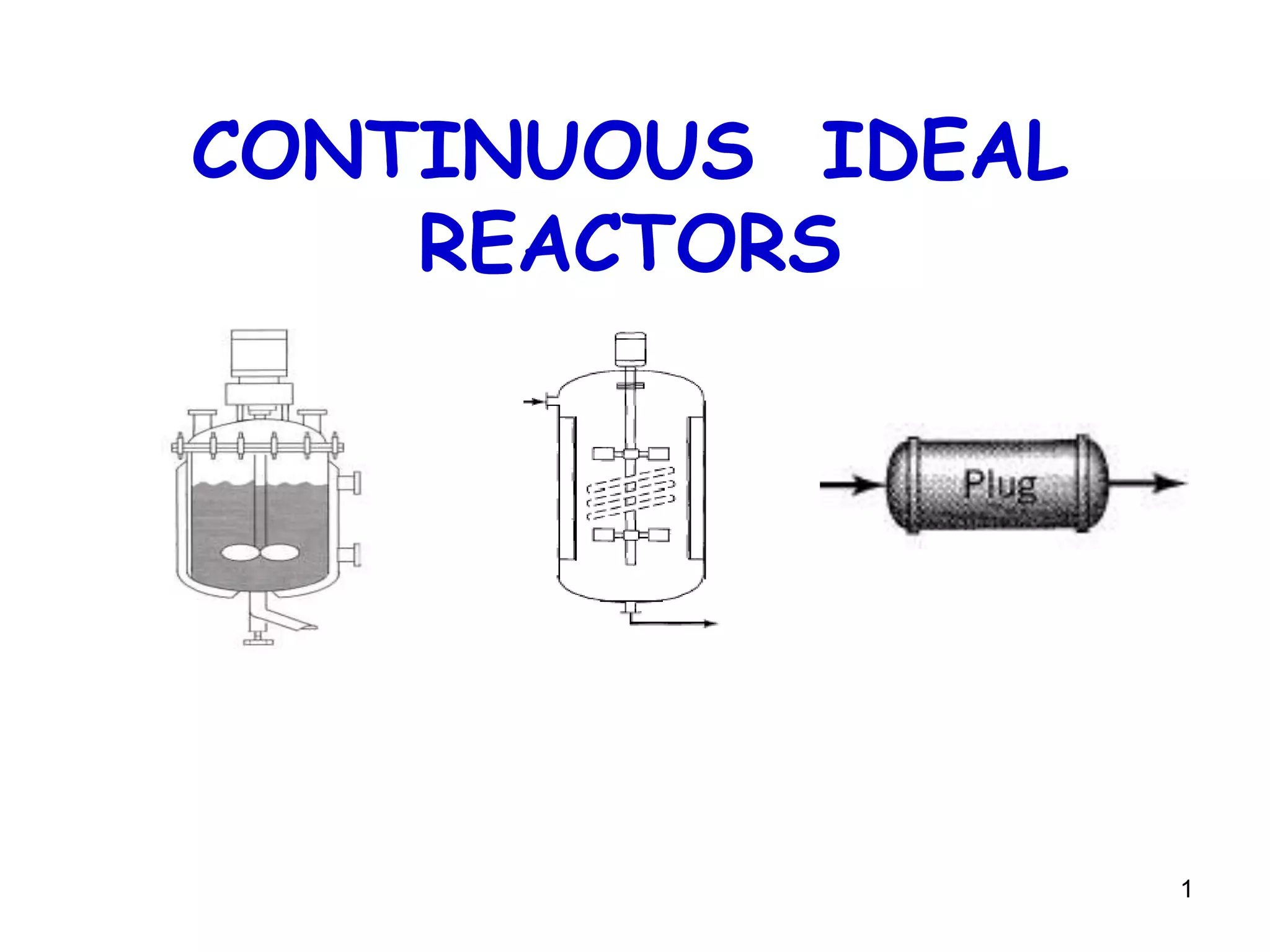
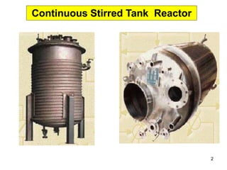
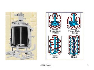
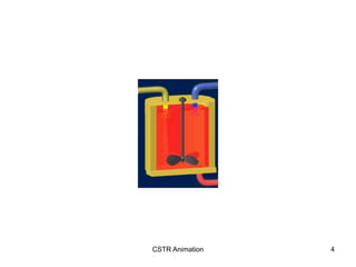
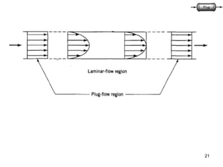
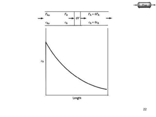
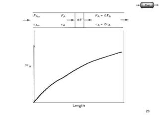
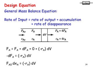
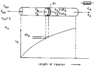
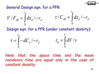
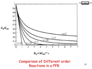
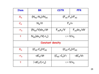
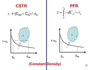
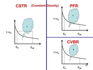
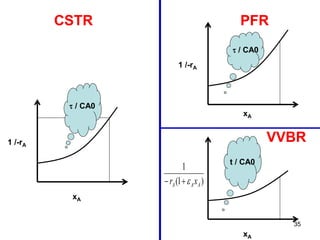
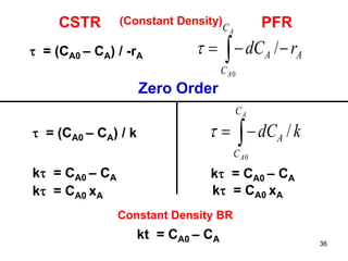
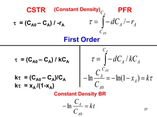
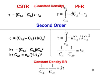
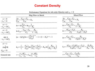
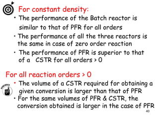
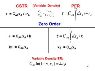
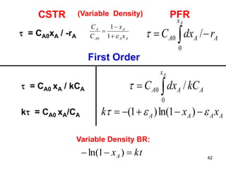
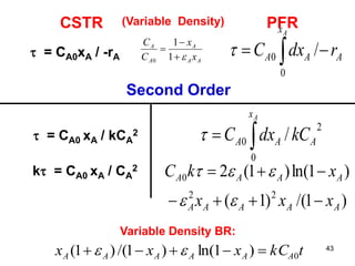
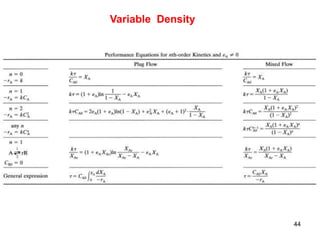
1
CONTINUOUS IDEAL
REACTORS
2
Continuous Stirred Tank Reactor
CSTR Contd. . . 3
CSTR Animation 4
CSTR Contd. . . 5
• Also called as Mixed, Backmix, Ideal stirred tank reactor
• Open system, operates under steady state conditions
• Reactants are continuously introduced and products are
continuously withdrawn
• Perfect mixing – contents have uniform properties
– No spatial variations
• Conditions at the exit are same as inside the reactor
• Used for homogenous liquid phase reactions where
constant agitation is required
• Eg. Sulfonation, Polymerization, plastics, explosives,
synthetic rubber etc.
CSTR Contd. . . 6
Advantages:
• Cheap to construct
• Good temperature control
• Reactor has large heat capacity
• Easy access to interiors
Disadvantages:
• Conversion per unit volume of the reactor is
smallest compared to other flow reactors
7
Fractional Conversion (xA):
0
0
A
AA
A
F
FF
x


0
0
A
AA
A
C
CC
x


Space time ():
Space time is the time required to process one
reactor volume of inlet material (feed) measured
at inlet conditions.  is the time required for a
volume of feed equal to the volume of the vessel
(V) to flow through the vessel.
 = V/v0 = sec
N.B. : Volume of vessel here means volume of Reaction Mixture.
(for constant density)
8
Space Velocity (S):
Space velocity (S) is the reciprocal of space time,
the number of reactor volumes of feed, measured
at inlet conditions, processed per unit time.
Mean Residence time tm:
The residence time is the length of time species
spend in the reactor. All molecules that enter may
not spend the same time in the reactor.
The distribution of residence times – RTD
The average length of time that molecules spend in
the reactor – mean residence time (tm)
tm = V/vE
9
)1(0 AAA xFF 
000 / AA CFv  lit
molmollit

secsec
For constant density:
)1(
)1(
0
0
0
AA
AAA
A xC
v
xF
v
F
C 


For variable density:
)1(
)1(
)1(
)1(
0
0
0
AA
A
A
AA
AAA
A
x
x
C
xv
xF
v
F
C
 





10
Stoichiometric Table – Flow Systems
B FB0 -(b/a)FA0xA FB= FA0(MB-(b/a)xA)
R FR0 +(r/a)FA0xA FR= FA0(MR+(r/a)xA)
S FS0 +(s/a)FA0xA FS= FA0(MS+(s/a)xA)
I FI0 0 FI = FI0
Total FT0 FT = FT0 + NA0δxA
Where: MI = FI0/FA0
δ = (r/a + s/a – b/a – 1)
aA + bB  rR + sS
For Constant density: CA = CA0(1-xA)
Species Initial Change Final moles
A FA0 -FA0xA FA= FA0(1-xA)
11
12
Design Equation
General Mass Balance Equation:
Rate of Input = rate of output + accumulation
+ rate of disappearance
FA0 = FA + 0 + (-rA) V
FA0 - FA = (-rA) V
FA0 xA = (-rA) V
V / FAo = xA / -rA
FA0
CA0
v0
FA
CA
V
xA
13
V / FAo = xA / -rA
General Design eqn. for a CSTR:
V / (v0 CA0) = xA / -rA
 / CA0 = xA / -rA
Design eqn. for a CSTR under constant density:
 = (CA0 – CA) / -rA
tm = V/vE
Note that the space time and the mean
residence time are equal only in the case of
constant density.
14
DA =kCA0
n-1 
Comparison of Different order
Reactions in a CSTR
15
Plug Flow Reactor
PFR Animation 16
The necessary and sufficient
condition for plug flow is the
residence time in the reactor to
be the same for all elements of
the fluid.
17
• PFR is also called as tubular reactor
• Residence time is same for all fluid elements
• Operated under steady state conditions
• Reactants are consumed as they flow down along the
length of the reactor
• Axial concentration gradients exist
• One long tube or a number of short tubes (see fig.)
• Choice of diameter depends on fabrication cost,
pumping cost and heat transfer needs
• Wide variety of applications in gas/liquid phase
• Eg.: Production of gasoline, cracking, synthesis of
ammonia, SO2 oxidation
18
19
(1) The flow in the vessel is Plug flow.
(2)There is no axial mixing of fluid inside the
vessel (i.e., in the direction of flow).
(3)There is complete radial mixing of fluid inside
the vessel (i.e., in the plane perpendicular to
the direction of flow).
(4)Properties may change continuously in the
direction of flow
(5)In the axial direction, each portion of fluid,
acts as a closed system in motion, not
exchanging material with the portion ahead of
it or behind it.
PFR Contd. . . 20
Advantages:
• Easily maintained as there are no moving parts
• High conversion per unit volume
• Unvarying product quality
• Good for studying rapid reactions
Disadvantages:
• Poor temperature control
• Hot spots may occur when used for exothermic
reactions
21
22
23
24
Design Equation
General Mass Balance Equation:
Rate of Input = rate of output + accumulation
+ rate of disappearance
FA = FA + dFA + 0 + (-rA) dV
-dFA = (-rA) dV
FA0 dxA = (-rA) dV
25
26
 
Ax
AAA rdxFV
0
0 //
General Design eqn. for a PFR:
 
Ax
AAA rdxC
0
0 //
Design eqn. for a PFR (under constant density):
 
Ax
AA rdC
0
/ 
V
m vdVt
0
/
Note that the space time and the mean
residence time are equal only in the case of
constant density.
27
CA/CA0
DA = kCA0
n-1 
Comparison of Different order
Reactions in a PFR
28
Item BR CSTR PFR
XA (NA0-NA)/NA0 (FA0-FA)/FA0
CA NA/V FA/v
-rA (NA0/V)dxA/dt FA0xA/V FA0dxA/dV
t NA0dxA/V(-rA)  = V/v0
Constant density
XA (CA0-CA)/CA0 (CA0-CA)/CA0
-rA -dCA/dt (CA0 -CA)/ -dCA/d
t -dCA/(-rA)  = V/v0
29
Algorithm for Isothermal Reactor Design
30
31
CSTR PFR
 / CA0 = xA / -rA  
Ax
AAA rdxC
0
0 //
1 /-rA
xA
 / CA0
 / CA0
32
CSTR PFR
V / FA0 = xA / -rA  
Ax
AAA rdxFV
0
0 //
33
CSTR PFR
1 /-rA

 = (CA0 – CA) / -rA  
Ax
AA rdC
0
/
CA
CA0
1 /-rA

CA
CA0
(Constant Density)
34
CSTR PFR
1 /-rA

CA CA0
1 /-rA

CA CA0
(Constant Density)
CVBR
1 /-rA
t
CA CA0
35
CSTR PFR
VVBR1 /-rA
xA
 / CA0
1 /-rA
xA
 / CA0
xA
t / CA0
)1(
1
AAA xr 
36
CSTR PFR
 = (CA0 – CA) / -rA  
A
A
C
C
AA rdC
0
/
(Constant Density)
Zero Order
 = (CA0 – CA) / k 
A
A
C
C
A kdC
0
/
k = CA0 – CA k = CA0 – CA
Constant Density BR
kt = CA0 – CA
k = CA0 xA k = CA0 xA
37
CSTR PFR
 = (CA0 – CA) / -rA  
A
A
C
C
AA rdC
0
/
(Constant Density)
First Order
 = (CA0 – CA) / kCA A
C
C
A CkdC
A
A

0
/
k = (CA0 – CA)/CA
Constant Density BR
kx
C
C
A
A
A
 )1ln(ln
0
kt
C
C
A
A

0
ln
k = xA /(1-xA)
38
CSTR PFR
 = (CA0 – CA) / -rA  
A
A
C
C
AA rdC
0
/
(Constant Density)
Second Order
 = (CA0 – CA) / kCA
2
2
0
/ A
C
C
A CkdC
A
A

k = (CA0 – CA)/CA
2
Constant Density BR
k
CC AA

0
11
kt
CC AA

0
11
k CA0 = xA /(1-xA)2
39
Constant Density
40
For constant density:
• The performance of the Batch reactor is
similar to that of PFR for all orders
• The performance of all the three reactors is
the same in case of zero order reaction
• The performance of PFR is superior to that
of a CSTR for all orders > 0
For all reaction orders > 0
• The volume of a CSTR required for obtaining a
given conversion is larger than that of PFR
• For the same volumes of PFR & CSTR, the
conversion obtained is larger in the case of PFR
41
CSTR PFR
 = CA0xA / -rA  
Ax
AAA rdxC
0
0 /
(Variable Density)
Zero Order
 = CA0 xA / k

Ax
AA kdxC
0
0 /
k = CA0 xA k = CA0xA
Variable Density BR:
tkxC AAAA   )1ln(0
AA
A
A
A
x
x
C
C



1
1
0
42
CSTR PFR
 = CA0xA / -rA
 
Ax
AAA rdxC
0
0 /
(Variable Density)
First Order
 = CA0 xA / kCA A
x
AA CkdxC
A

0
0 /
k = CA0 xA/CA
Variable Density BR:
AAAA xxk   )1ln()1(
ktxA  )1ln(
AA
A
A
A
x
x
C
C



1
1
0
43
CSTR PFR
 = CA0xA / -rA  
Ax
AAA rdxC
0
0 /
(Variable Density)
Second Order
 = CA0 xA / kCA
2
2
0
0 / A
x
AA CkdxC
A

Variable Density BR:
)1ln()1(20 AAAA xkC  
)1/()1( 22
AAAAA xxx  
tkCxxx AAAAAA 0)1ln()1/()1(  
AA
A
A
A
x
x
C
C



1
1
0
k = CA0 xA / CA
2
44
Variable Density
45
Relative performance of plug flow and
continuous-flow stirred tank reactors
Fraction unreacted is larger in CSTR for a given Da
46
Comparison of reactor volume required for a given
conversion for a first-order reaction in a PFR and a CSTR
• For small conversions VCSTR/VPFR = 1 (selection of reactor
not very critical).
• For large conversions, VCSTR/VPFR is very large (selection of
reactor very critical).
47
For Variable density:
• The performance of CSTR & PFR is similar in
case of zero order (irrespective of constant /
variable density)
• The performance of BR is different from the
performance of PFR (the performance was
similar in the case of constant density)
• The performance of PFR is superior to that of
a CSTR for all orders > 0 (same as constant
density)
48
Criteria Batch CSTR PFR
Reactor size for given conversion + - +
Simplicity and Cost + + -
Continuous operation - + +
Large throughput - + +
Cleanout + + -
On-line analysis - + +
Product quality - + +
Comparison of possible advantages (+) and Disadvantages (-)
for Batch, CSTR and PFR Reactors
49
ANY CLARIFICATIONS ?
Abbey, Edward
That which today calls itself science gives us more and more information,
an indigestible glut of information, and less and less understanding.

ideal reactors

  • 1.
  • 2.
  • 3.
  • 4.
  • 5.
    CSTR Contd. .. 5 • Also called as Mixed, Backmix, Ideal stirred tank reactor • Open system, operates under steady state conditions • Reactants are continuously introduced and products are continuously withdrawn • Perfect mixing – contents have uniform properties – No spatial variations • Conditions at the exit are same as inside the reactor • Used for homogenous liquid phase reactions where constant agitation is required • Eg. Sulfonation, Polymerization, plastics, explosives, synthetic rubber etc.
  • 6.
    CSTR Contd. .. 6 Advantages: • Cheap to construct • Good temperature control • Reactor has large heat capacity • Easy access to interiors Disadvantages: • Conversion per unit volume of the reactor is smallest compared to other flow reactors
  • 7.
    7 Fractional Conversion (xA): 0 0 A AA A F FF x   0 0 A AA A C CC x   Spacetime (): Space time is the time required to process one reactor volume of inlet material (feed) measured at inlet conditions.  is the time required for a volume of feed equal to the volume of the vessel (V) to flow through the vessel.  = V/v0 = sec N.B. : Volume of vessel here means volume of Reaction Mixture. (for constant density)
  • 8.
    8 Space Velocity (S): Spacevelocity (S) is the reciprocal of space time, the number of reactor volumes of feed, measured at inlet conditions, processed per unit time. Mean Residence time tm: The residence time is the length of time species spend in the reactor. All molecules that enter may not spend the same time in the reactor. The distribution of residence times – RTD The average length of time that molecules spend in the reactor – mean residence time (tm) tm = V/vE
  • 9.
    9 )1(0 AAA xFF 000 / AA CFv  lit molmollit  secsec For constant density: )1( )1( 0 0 0 AA AAA A xC v xF v F C    For variable density: )1( )1( )1( )1( 0 0 0 AA A A AA AAA A x x C xv xF v F C       
  • 10.
    10 Stoichiometric Table –Flow Systems B FB0 -(b/a)FA0xA FB= FA0(MB-(b/a)xA) R FR0 +(r/a)FA0xA FR= FA0(MR+(r/a)xA) S FS0 +(s/a)FA0xA FS= FA0(MS+(s/a)xA) I FI0 0 FI = FI0 Total FT0 FT = FT0 + NA0δxA Where: MI = FI0/FA0 δ = (r/a + s/a – b/a – 1) aA + bB  rR + sS For Constant density: CA = CA0(1-xA) Species Initial Change Final moles A FA0 -FA0xA FA= FA0(1-xA)
  • 11.
  • 12.
    12 Design Equation General MassBalance Equation: Rate of Input = rate of output + accumulation + rate of disappearance FA0 = FA + 0 + (-rA) V FA0 - FA = (-rA) V FA0 xA = (-rA) V V / FAo = xA / -rA FA0 CA0 v0 FA CA V xA
  • 13.
    13 V / FAo= xA / -rA General Design eqn. for a CSTR: V / (v0 CA0) = xA / -rA  / CA0 = xA / -rA Design eqn. for a CSTR under constant density:  = (CA0 – CA) / -rA tm = V/vE Note that the space time and the mean residence time are equal only in the case of constant density.
  • 14.
    14 DA =kCA0 n-1  Comparisonof Different order Reactions in a CSTR
  • 15.
  • 16.
    PFR Animation 16 Thenecessary and sufficient condition for plug flow is the residence time in the reactor to be the same for all elements of the fluid.
  • 17.
    17 • PFR isalso called as tubular reactor • Residence time is same for all fluid elements • Operated under steady state conditions • Reactants are consumed as they flow down along the length of the reactor • Axial concentration gradients exist • One long tube or a number of short tubes (see fig.) • Choice of diameter depends on fabrication cost, pumping cost and heat transfer needs • Wide variety of applications in gas/liquid phase • Eg.: Production of gasoline, cracking, synthesis of ammonia, SO2 oxidation
  • 18.
  • 19.
    19 (1) The flowin the vessel is Plug flow. (2)There is no axial mixing of fluid inside the vessel (i.e., in the direction of flow). (3)There is complete radial mixing of fluid inside the vessel (i.e., in the plane perpendicular to the direction of flow). (4)Properties may change continuously in the direction of flow (5)In the axial direction, each portion of fluid, acts as a closed system in motion, not exchanging material with the portion ahead of it or behind it.
  • 20.
    PFR Contd. .. 20 Advantages: • Easily maintained as there are no moving parts • High conversion per unit volume • Unvarying product quality • Good for studying rapid reactions Disadvantages: • Poor temperature control • Hot spots may occur when used for exothermic reactions
  • 21.
  • 22.
  • 23.
  • 24.
    24 Design Equation General MassBalance Equation: Rate of Input = rate of output + accumulation + rate of disappearance FA = FA + dFA + 0 + (-rA) dV -dFA = (-rA) dV FA0 dxA = (-rA) dV
  • 25.
  • 26.
    26   Ax AAA rdxFV 0 0// General Design eqn. for a PFR:   Ax AAA rdxC 0 0 // Design eqn. for a PFR (under constant density):   Ax AA rdC 0 /  V m vdVt 0 / Note that the space time and the mean residence time are equal only in the case of constant density.
  • 27.
    27 CA/CA0 DA = kCA0 n-1 Comparison of Different order Reactions in a PFR
  • 28.
    28 Item BR CSTRPFR XA (NA0-NA)/NA0 (FA0-FA)/FA0 CA NA/V FA/v -rA (NA0/V)dxA/dt FA0xA/V FA0dxA/dV t NA0dxA/V(-rA)  = V/v0 Constant density XA (CA0-CA)/CA0 (CA0-CA)/CA0 -rA -dCA/dt (CA0 -CA)/ -dCA/d t -dCA/(-rA)  = V/v0
  • 29.
  • 30.
  • 31.
    31 CSTR PFR  /CA0 = xA / -rA   Ax AAA rdxC 0 0 // 1 /-rA xA  / CA0  / CA0
  • 32.
    32 CSTR PFR V /FA0 = xA / -rA   Ax AAA rdxFV 0 0 //
  • 33.
    33 CSTR PFR 1 /-rA  = (CA0 – CA) / -rA   Ax AA rdC 0 / CA CA0 1 /-rA  CA CA0 (Constant Density)
  • 34.
    34 CSTR PFR 1 /-rA  CACA0 1 /-rA  CA CA0 (Constant Density) CVBR 1 /-rA t CA CA0
  • 35.
    35 CSTR PFR VVBR1 /-rA xA / CA0 1 /-rA xA  / CA0 xA t / CA0 )1( 1 AAA xr 
  • 36.
    36 CSTR PFR  =(CA0 – CA) / -rA   A A C C AA rdC 0 / (Constant Density) Zero Order  = (CA0 – CA) / k  A A C C A kdC 0 / k = CA0 – CA k = CA0 – CA Constant Density BR kt = CA0 – CA k = CA0 xA k = CA0 xA
  • 37.
    37 CSTR PFR  =(CA0 – CA) / -rA   A A C C AA rdC 0 / (Constant Density) First Order  = (CA0 – CA) / kCA A C C A CkdC A A  0 / k = (CA0 – CA)/CA Constant Density BR kx C C A A A  )1ln(ln 0 kt C C A A  0 ln k = xA /(1-xA)
  • 38.
    38 CSTR PFR  =(CA0 – CA) / -rA   A A C C AA rdC 0 / (Constant Density) Second Order  = (CA0 – CA) / kCA 2 2 0 / A C C A CkdC A A  k = (CA0 – CA)/CA 2 Constant Density BR k CC AA  0 11 kt CC AA  0 11 k CA0 = xA /(1-xA)2
  • 39.
  • 40.
    40 For constant density: •The performance of the Batch reactor is similar to that of PFR for all orders • The performance of all the three reactors is the same in case of zero order reaction • The performance of PFR is superior to that of a CSTR for all orders > 0 For all reaction orders > 0 • The volume of a CSTR required for obtaining a given conversion is larger than that of PFR • For the same volumes of PFR & CSTR, the conversion obtained is larger in the case of PFR
  • 41.
    41 CSTR PFR  =CA0xA / -rA   Ax AAA rdxC 0 0 / (Variable Density) Zero Order  = CA0 xA / k  Ax AA kdxC 0 0 / k = CA0 xA k = CA0xA Variable Density BR: tkxC AAAA   )1ln(0 AA A A A x x C C    1 1 0
  • 42.
    42 CSTR PFR  =CA0xA / -rA   Ax AAA rdxC 0 0 / (Variable Density) First Order  = CA0 xA / kCA A x AA CkdxC A  0 0 / k = CA0 xA/CA Variable Density BR: AAAA xxk   )1ln()1( ktxA  )1ln( AA A A A x x C C    1 1 0
  • 43.
    43 CSTR PFR  =CA0xA / -rA   Ax AAA rdxC 0 0 / (Variable Density) Second Order  = CA0 xA / kCA 2 2 0 0 / A x AA CkdxC A  Variable Density BR: )1ln()1(20 AAAA xkC   )1/()1( 22 AAAAA xxx   tkCxxx AAAAAA 0)1ln()1/()1(   AA A A A x x C C    1 1 0 k = CA0 xA / CA 2
  • 44.
  • 45.
    45 Relative performance ofplug flow and continuous-flow stirred tank reactors Fraction unreacted is larger in CSTR for a given Da
  • 46.
    46 Comparison of reactorvolume required for a given conversion for a first-order reaction in a PFR and a CSTR • For small conversions VCSTR/VPFR = 1 (selection of reactor not very critical). • For large conversions, VCSTR/VPFR is very large (selection of reactor very critical).
  • 47.
    47 For Variable density: •The performance of CSTR & PFR is similar in case of zero order (irrespective of constant / variable density) • The performance of BR is different from the performance of PFR (the performance was similar in the case of constant density) • The performance of PFR is superior to that of a CSTR for all orders > 0 (same as constant density)
  • 48.
    48 Criteria Batch CSTRPFR Reactor size for given conversion + - + Simplicity and Cost + + - Continuous operation - + + Large throughput - + + Cleanout + + - On-line analysis - + + Product quality - + + Comparison of possible advantages (+) and Disadvantages (-) for Batch, CSTR and PFR Reactors
  • 49.
    49 ANY CLARIFICATIONS ? Abbey,Edward That which today calls itself science gives us more and more information, an indigestible glut of information, and less and less understanding.