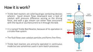
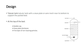
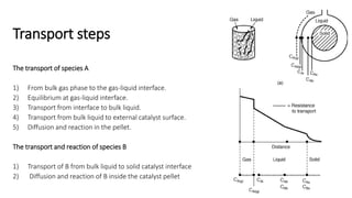
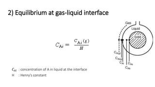
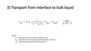
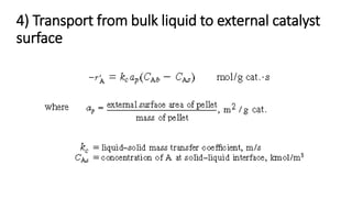
Trickle-bed reactor
Eng. Tareq Al-Anber
How it is work?
• Trickle bed reactors are solid-liquid-gas contacting devices
wherein liquid stream flows downward over a bed of
catalyst with pressure difference serving as the driving
force, and with a gas stream can either flow concurrent
with the liquid or countercurrent to it through the bed.
• It is named Trickle Bed Reactor, because of its operation in
a trickle-flow system.
• The fluid flows over catalyst particles and forms fine films.
• Trickle bed reactors are primarily operated in continuous
mode but are sometimes used in semi-batch processes.
Design
• Tubular tank tubular tank with a sieve plate or wire mesh near its bottom to
support the packed bed.
• At the top of the bed:
Bubble cap.
Sieve plate distributor.
Fine layer of non-reacting particles.
Types
• Conventional tickle bed reactors
Randomly packed beds of porous catalyst particles.
• Semi structures tickle bed reactors
 Structured packing catalyst.
 Lower pressure drop and eliminates diffusion as a limiting factor to the
reaction.
• Micro-tickle bed reactor
 Micro-channel packed with catalyst particles.
 Better control of reaction parameters and enhance process safety.
Transport steps
The transport of species A
1) From bulk gas phase to the gas-liquid interface.
2) Equilibrium at gas-liquid interface.
3) Transport from interface to bulk liquid.
4) Transport from bulk liquid to external catalyst surface.
5) Diffusion and reaction in the pellet.
The transport and reaction of species B
1) Transport of B from bulk liquid to solid catalyst interface
2) Diffusion and reaction of B inside the catalyst pellet
1) From bulk gas phase to gas-liquid interface.
2) Equilibrium at gas-liquid interface
𝐶𝐴𝑖 : concentration of A in liquid at the interface
H : Henry's constant
3) Transport from interface to bulk liquid
where
𝑘1 : liquid-phase mass transfer coefficient, m/s
𝐶𝐴𝑖 : concentration of A in liquid at the interface, kmol/m 3
𝐶𝐴𝑏 : bulk liquid concentration of A, kmol/m 3
4) Transport from bulk liquid to external catalyst
surface
5) Diffusion and reaction in the pellet.
Combining Equations
• The overall rate equation for A
Mole balance on species A gives
𝑘 𝑣𝑔is the overall transfer coefficient for the gas into the pellet (m 3 of gas/g cat. s)
6) Transport of B from bulk liquid to solid catalyst
interface
Where 𝐶 𝐵 and 𝐶 𝐵𝑠 are the concentrations of B in the bulk fluid and at the solid interface,
respectively.
7) Diffusion and reaction of B inside the
catalyst pellet.
• Combining Equations and rearranging, we have
The overall rate equation for B
A mole balance on species B gives
Mass Transfer of the Gaseous Reactant Limiting
• For this situation we assume that either the first three terms in the denominator
of Equation are dominant or that the liquid-phase concentration of species B does
not vary significantly through the trickle bed. For these conditions 𝑘 𝑣𝑔.
• Is constant and we can integrate the mole balance. For negligible volume change
𝑋𝑖= 0, then
Catalyst weight necessary to achieve a conversion 𝑋 𝐴 of gas phase reactant
Mass Transfer and Reaction of Liquid Species Limiting
• we assume that the liquid phase is entirely saturated with gas throughout the
column. As a result, CAs is a constant. Consequently, we can integrate the
combined mole balance and rate law to give kvg , kvl.
Catalyst weight necessary to achieve a conversion 𝑋 𝐵 of gas phase reactant
Advantages
• Can be used for three - phase reactions.
• Lower total energy consumption since solids are stagnant, not suspended in slurry.
• Simple to operate under high temperatures and pressures.
• Lower catalyst attrition
Disadvantages
• Hot spots may develop due to solvent evaporation.
• Channeling may occur, leading to inefficiencies.
• Difficult to control vessel parameters.
• Lower performance when liquid not uniformly distributed.
• Difficult to scale up due to dependence on fluid dynamics of system.
Usage Examples
• Trickle beds are used in such processes as the hydrodesulfurization of
heavy oil stocks
• The hydro treating of lubricating oils
• Oxidation of harmful chemical compounds in wastewater

Trickle bed reactor

  • 1.
  • 2.
    How it iswork? • Trickle bed reactors are solid-liquid-gas contacting devices wherein liquid stream flows downward over a bed of catalyst with pressure difference serving as the driving force, and with a gas stream can either flow concurrent with the liquid or countercurrent to it through the bed. • It is named Trickle Bed Reactor, because of its operation in a trickle-flow system. • The fluid flows over catalyst particles and forms fine films. • Trickle bed reactors are primarily operated in continuous mode but are sometimes used in semi-batch processes.
  • 3.
    Design • Tubular tanktubular tank with a sieve plate or wire mesh near its bottom to support the packed bed. • At the top of the bed: Bubble cap. Sieve plate distributor. Fine layer of non-reacting particles.
  • 4.
    Types • Conventional ticklebed reactors Randomly packed beds of porous catalyst particles. • Semi structures tickle bed reactors  Structured packing catalyst.  Lower pressure drop and eliminates diffusion as a limiting factor to the reaction. • Micro-tickle bed reactor  Micro-channel packed with catalyst particles.  Better control of reaction parameters and enhance process safety.
  • 5.
    Transport steps The transportof species A 1) From bulk gas phase to the gas-liquid interface. 2) Equilibrium at gas-liquid interface. 3) Transport from interface to bulk liquid. 4) Transport from bulk liquid to external catalyst surface. 5) Diffusion and reaction in the pellet. The transport and reaction of species B 1) Transport of B from bulk liquid to solid catalyst interface 2) Diffusion and reaction of B inside the catalyst pellet
  • 6.
    1) From bulkgas phase to gas-liquid interface.
  • 7.
    2) Equilibrium atgas-liquid interface 𝐶𝐴𝑖 : concentration of A in liquid at the interface H : Henry's constant
  • 8.
    3) Transport frominterface to bulk liquid where 𝑘1 : liquid-phase mass transfer coefficient, m/s 𝐶𝐴𝑖 : concentration of A in liquid at the interface, kmol/m 3 𝐶𝐴𝑏 : bulk liquid concentration of A, kmol/m 3
  • 9.
    4) Transport frombulk liquid to external catalyst surface
  • 10.
    5) Diffusion andreaction in the pellet.
  • 11.
    Combining Equations • Theoverall rate equation for A
  • 12.
    Mole balance onspecies A gives 𝑘 𝑣𝑔is the overall transfer coefficient for the gas into the pellet (m 3 of gas/g cat. s)
  • 13.
    6) Transport ofB from bulk liquid to solid catalyst interface Where 𝐶 𝐵 and 𝐶 𝐵𝑠 are the concentrations of B in the bulk fluid and at the solid interface, respectively.
  • 14.
    7) Diffusion andreaction of B inside the catalyst pellet. • Combining Equations and rearranging, we have The overall rate equation for B
  • 15.
    A mole balanceon species B gives
  • 16.
    Mass Transfer ofthe Gaseous Reactant Limiting • For this situation we assume that either the first three terms in the denominator of Equation are dominant or that the liquid-phase concentration of species B does not vary significantly through the trickle bed. For these conditions 𝑘 𝑣𝑔. • Is constant and we can integrate the mole balance. For negligible volume change 𝑋𝑖= 0, then Catalyst weight necessary to achieve a conversion 𝑋 𝐴 of gas phase reactant
  • 17.
    Mass Transfer andReaction of Liquid Species Limiting • we assume that the liquid phase is entirely saturated with gas throughout the column. As a result, CAs is a constant. Consequently, we can integrate the combined mole balance and rate law to give kvg , kvl. Catalyst weight necessary to achieve a conversion 𝑋 𝐵 of gas phase reactant
  • 18.
    Advantages • Can beused for three - phase reactions. • Lower total energy consumption since solids are stagnant, not suspended in slurry. • Simple to operate under high temperatures and pressures. • Lower catalyst attrition
  • 19.
    Disadvantages • Hot spotsmay develop due to solvent evaporation. • Channeling may occur, leading to inefficiencies. • Difficult to control vessel parameters. • Lower performance when liquid not uniformly distributed. • Difficult to scale up due to dependence on fluid dynamics of system.
  • 20.
    Usage Examples • Tricklebeds are used in such processes as the hydrodesulfurization of heavy oil stocks • The hydro treating of lubricating oils • Oxidation of harmful chemical compounds in wastewater