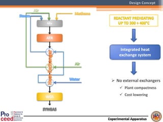
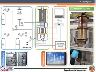
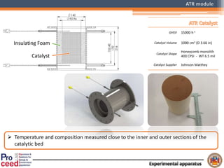
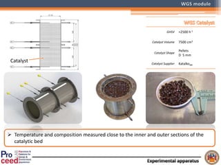
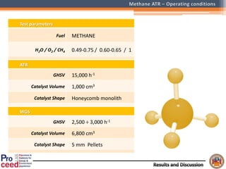
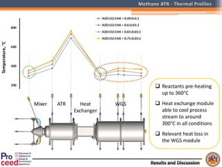
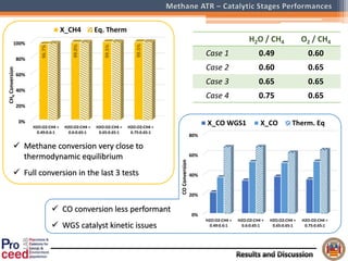
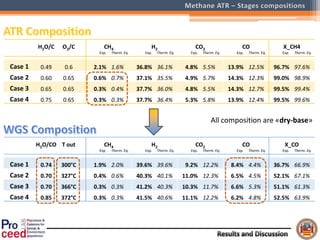
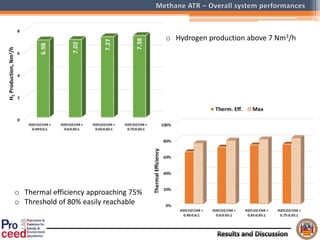
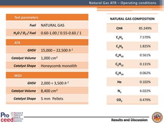
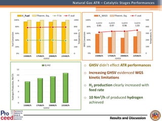
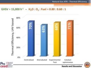
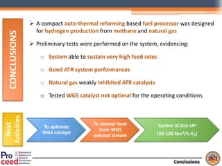
HYDROGEN PRODUCTION BY A THERMALLY INTEGRATED
ATR BASED FUEL PROCESSOR
V. Palma1, A. Ricca1, B. Addeo1, G. Paolillo2, P. Ciambelli1
1 Department of Industrial Engineering - University of Salerno, Fisciano (SA) - ITALY
2 R&D - SOL S.p.A, Monza (MB), ITALY
o Growing world energy demand
o Depletion of fossil fuels
Solar Nuclear GeologicalEolic
Hydrogen
=
Energetic vector
Green
Energy
Hydrogen
 Steam Reforming
 Partial Oxidation
 Autothermal Reforming
Preliminary syngas purification
 Preferential oxidation
 Membrane separation
 Pressure swing adsorption
HC
Air H2O
Reformer
Water Gas Shift
Further purification
HYDROGEN
H2
Distributed H2 production for heat
and energy power generation
High compactness and thermal
efficiency of the reactor
Auto-Thermal Reforming (ATR)
Partial Oxidation
molKJH 3.206 molKJH 6.35
Steam Reforming
 To design and set-up a fuel processor based on auto-
thermal reforming (H2 productivity 10 Nm3/h)
 ATR – WGS Integration
 Compactness
 Thermal Integration
 To perform preliminary tests
 Methane
 Natural Gas
AIMS OF THIS WORK
Mix
ATR
WGS
Integrated heat
exchange system
 No external exchangers
 Plant compactness
 Cost lowering
FEEDSECTION
ANALYSISSYSTEM
REACTION SECTION
 Temperature and composition measured close to the inner and outer sections of the
catalytic bed
GHSV 15000 h-1
Catalyst Volume 1000 cm3 (D 3.66 in)
Catalyst Shape
Honeycomb monolith
400 CPSI - WT 6.5 mil
Catalyst Supplier Johnson Matthey
Catalyst
Insulating Foam
 Temperature and composition measured close to the inner and outer sections of the
catalytic bed
GHSV ≈2500 h-1
Catalyst Volume 7500 cm3
Catalyst Shape
Pellets
D 5 mm
Catalyst Supplier KatalkoJM
Catalyst
Steam Air Liquid water
Coils 5 9 10
Tube per coils 9 5 9
Surface (m2) 0.032 0.032 0.065
 The use of coils increases heat exchange efficiency
 Several coils mounted parallel-way to reduce
pressure drops
 Exchangers arrangement maximizes heat transfer
and avoids methane cracking
Test parameters
Fuel METHANE
H2O / O2 / CH4 0.49-0.75 / 0.60-0.65 / 1
ATR
GHSV 15,000 h-1
Catalyst Volume 1,000 cm3
Catalyst Shape Honeycomb monolith
WGS
GHSV 2,500 ÷ 3,000 h-1
Catalyst Volume 6,800 cm3
Catalyst Shape 5 mm Pellets
Mixer ATR Heat
Exchanger
WGS
 Reactants pre-heating
up to 360°C
 Heat exchange module
able to cool process
stream to around
300°C in all conditions
 Relevant heat loss in
the WGS module
0%
20%
40%
60%
80%
100%
H2O:O2:CH4 =
0.49:0.6:1
H2O:O2:CH4 =
0.6:0.65:1
H2O:O2:CH4 =
0.65:0.65:1
H2O:O2:CH4 =
0.75:0.65:1
96.7%
99.0%
99.5%
99.5%
CH4Conversion
X_CH4 Eq. Therm
0%
20%
40%
60%
80%
H2O:O2:CH4 =
0.49:0.6:1
H2O:O2:CH4 =
0.6:0.65:1
H2O:O2:CH4 =
0.65:0.65:1
H2O:O2:CH4 =
0.75:0.65:1
COConversion
X_CO WGS1 X_CO Therm. Eq
 Methane conversion very close to
thermodynamic equilibrium
 Full conversion in the last 3 tests
 CO conversion less performant
 WGS catalyst kinetic issues
H2O / CH4 O2 / CH4
Case 1 0.49 0.60
Case 2 0.60 0.65
Case 3 0.65 0.65
Case 4 0.75 0.65
H2O/CO T out CH4 H2 CO2 CO X_CO
Exp. Therm. Eq. Exp. Therm. Eq. Exp. Therm. Eq. Exp. Therm. Eq. Exp. Therm. Eq.
Case 1 0.74 300°C 1.9% 2.0% 39.6% 39.6% 9.2% 12.2% 8.4% 4.4% 36.7% 66.9%
Case 2 0.70 327°C 0.4% 0.6% 40.3% 40.1% 11.0% 12.3% 6.5% 4.5% 52.1% 67.1%
Case 3 0.70 366°C 0.3% 0.3% 41.2% 40.3% 10.3% 11.7% 6.6% 5.3% 51.1% 61.3%
Case 4 0.85 372°C 0.3% 0.3% 41.5% 40.6% 11.1% 12.2% 6.2% 4.8% 52.5% 63.9%
H2O/C O2/C CH4 H2 CO2 CO X_CH4
Exp. Therm. Eq. Exp. Therm. Eq. Exp. Therm. Eq. Exp. Therm. Eq. Exp. Therm. Eq.
Case 1 0.49 0.6 2.1% 1.6% 36.8% 36.1% 4.8% 5.5% 13.9% 12.5% 96.7% 97.6%
Case 2 0.60 0.65 0.6% 0.7% 37.1% 35.5% 4.9% 5.7% 14.3% 12.3% 99.0% 98.9%
Case 3 0.65 0.65 0.3% 0.4% 37.7% 36.0% 4.8% 5.5% 14.3% 12.7% 99.5% 99.4%
Case 4 0.75 0.65 0.3% 0.3% 37.7% 36.4% 5.3% 5.8% 13.9% 12.4% 99.5% 99.6%
All composition are «dry-base»
o Hydrogen production above 7 Nm3/h
o Thermal efficiency approaching 75%
o Threshold of 80% easily reachable
Test parameters
Fuel NATURAL GAS
H2O / O2 / Fuel 0.60-1.00 / 0.55-0.60 / 1
ATR
GHSV 15,000 – 22,500 h-1
Catalyst Volume 1,000 cm3
Catalyst Shape Honeycomb monolith
WGS
GHSV 2,000 ÷ 3,500 h-1
Catalyst Volume 8,400 cm3
Catalyst Shape 5 mm Pellets
NATURAL GAS COMPOSITION
CH4 85.249%
C2H6 7.570%
C3H8 1.825%
C4H10 0.561%
C5H12 0.131%
C6H14 0.062%
He 0.102%
N2 4.022%
CO2 0.479%
Mixer ATR Heat
Exchanger
WGS
 O2/Fuel ratio < 0.6
critical for the system
 Steam to feed ratio =
0.8 showed highest
performances
o ATR quite approached equilibrium
o O2/fuel ratio effected performances
o WGS stage far from equilibrium
o Both kinetic and thermodynamic
issues
o H2 production quite constant in
investigated conditions
H2O/CO
0.78
H2O/CO
1.67
H2O/CO
0.85
H2O/CO
1.17
H2O/CO
1.30
Fuel
Mixer ATR Heat
Exchanger
WGS
 Feed rate seems to not
effect temperature
profile
 System adiabaticity
 Heat exchangers well
balanced
o GHSV didn’t effect ATR performances
o Increasing GHSV evidenced WGS
kinetic limitations
o H2 production clearly increased with
feed rate
o 10 Nm3/h of produced hydrogen
achieved
H2O/CO
0.85
H2O/CO
0.97
H2O/CO
0.96
H2O/CO
1.03
Fuel
0%
20%
40%
60%
80%
Centralized Distrubuted Experimental
Test
Catalyst
optimizaton
70%
63%
68%
71%
ThermalEfficiency,LHVbased
GHSV = 15,000 h-1 - H2O : O2 : Fuel = 0.80 : 0.60 : 1
 A compact auto-thermal reforming based fuel processor was designed
for hydrogen production from methane and natural gas
 Preliminary tests were performed on the system, evidencing:
o System able to sustain very high feed rates
o Good ATR system performances
o Natural gas weakly inhibited ATR catalysts
o Tested WGS catalyst not optimal for the operating conditions
To optimize
WGS catalyst
To recover heat
from WGS
exhaust stream
System SCALE-UP
(50-100 Nm3/h H2)
CONCLUSIONS
Next
Activities
The research leading to those results has received funding from the
PON 01_02545 “Sviluppo di sistemi per la produzione distribuita
di idrogeno e syngas basati su reforming auto termico catalitico
multifuel” project.
Antonio Ricca
PhD, Chemical Engineer
--------------------------------------------------------------
Department of Industrial Engineering
University of Salerno
aricca@unisa.it

Hydrogen production by a thermally integrated ATR based fuel processor

  • 1.
    HYDROGEN PRODUCTION BYA THERMALLY INTEGRATED ATR BASED FUEL PROCESSOR V. Palma1, A. Ricca1, B. Addeo1, G. Paolillo2, P. Ciambelli1 1 Department of Industrial Engineering - University of Salerno, Fisciano (SA) - ITALY 2 R&D - SOL S.p.A, Monza (MB), ITALY
  • 2.
    o Growing worldenergy demand o Depletion of fossil fuels Solar Nuclear GeologicalEolic Hydrogen = Energetic vector Green Energy Hydrogen
  • 3.
     Steam Reforming Partial Oxidation  Autothermal Reforming Preliminary syngas purification  Preferential oxidation  Membrane separation  Pressure swing adsorption HC Air H2O Reformer Water Gas Shift Further purification HYDROGEN H2
  • 4.
    Distributed H2 productionfor heat and energy power generation High compactness and thermal efficiency of the reactor Auto-Thermal Reforming (ATR) Partial Oxidation molKJH 3.206 molKJH 6.35 Steam Reforming
  • 5.
     To designand set-up a fuel processor based on auto- thermal reforming (H2 productivity 10 Nm3/h)  ATR – WGS Integration  Compactness  Thermal Integration  To perform preliminary tests  Methane  Natural Gas AIMS OF THIS WORK
  • 7.
    Mix ATR WGS Integrated heat exchange system No external exchangers  Plant compactness  Cost lowering
  • 8.
  • 9.
     Temperature andcomposition measured close to the inner and outer sections of the catalytic bed GHSV 15000 h-1 Catalyst Volume 1000 cm3 (D 3.66 in) Catalyst Shape Honeycomb monolith 400 CPSI - WT 6.5 mil Catalyst Supplier Johnson Matthey Catalyst Insulating Foam
  • 10.
     Temperature andcomposition measured close to the inner and outer sections of the catalytic bed GHSV ≈2500 h-1 Catalyst Volume 7500 cm3 Catalyst Shape Pellets D 5 mm Catalyst Supplier KatalkoJM Catalyst
  • 11.
    Steam Air Liquidwater Coils 5 9 10 Tube per coils 9 5 9 Surface (m2) 0.032 0.032 0.065  The use of coils increases heat exchange efficiency  Several coils mounted parallel-way to reduce pressure drops  Exchangers arrangement maximizes heat transfer and avoids methane cracking
  • 14.
    Test parameters Fuel METHANE H2O/ O2 / CH4 0.49-0.75 / 0.60-0.65 / 1 ATR GHSV 15,000 h-1 Catalyst Volume 1,000 cm3 Catalyst Shape Honeycomb monolith WGS GHSV 2,500 ÷ 3,000 h-1 Catalyst Volume 6,800 cm3 Catalyst Shape 5 mm Pellets
  • 15.
    Mixer ATR Heat Exchanger WGS Reactants pre-heating up to 360°C  Heat exchange module able to cool process stream to around 300°C in all conditions  Relevant heat loss in the WGS module
  • 16.
    0% 20% 40% 60% 80% 100% H2O:O2:CH4 = 0.49:0.6:1 H2O:O2:CH4 = 0.6:0.65:1 H2O:O2:CH4= 0.65:0.65:1 H2O:O2:CH4 = 0.75:0.65:1 96.7% 99.0% 99.5% 99.5% CH4Conversion X_CH4 Eq. Therm 0% 20% 40% 60% 80% H2O:O2:CH4 = 0.49:0.6:1 H2O:O2:CH4 = 0.6:0.65:1 H2O:O2:CH4 = 0.65:0.65:1 H2O:O2:CH4 = 0.75:0.65:1 COConversion X_CO WGS1 X_CO Therm. Eq  Methane conversion very close to thermodynamic equilibrium  Full conversion in the last 3 tests  CO conversion less performant  WGS catalyst kinetic issues H2O / CH4 O2 / CH4 Case 1 0.49 0.60 Case 2 0.60 0.65 Case 3 0.65 0.65 Case 4 0.75 0.65
  • 17.
    H2O/CO T outCH4 H2 CO2 CO X_CO Exp. Therm. Eq. Exp. Therm. Eq. Exp. Therm. Eq. Exp. Therm. Eq. Exp. Therm. Eq. Case 1 0.74 300°C 1.9% 2.0% 39.6% 39.6% 9.2% 12.2% 8.4% 4.4% 36.7% 66.9% Case 2 0.70 327°C 0.4% 0.6% 40.3% 40.1% 11.0% 12.3% 6.5% 4.5% 52.1% 67.1% Case 3 0.70 366°C 0.3% 0.3% 41.2% 40.3% 10.3% 11.7% 6.6% 5.3% 51.1% 61.3% Case 4 0.85 372°C 0.3% 0.3% 41.5% 40.6% 11.1% 12.2% 6.2% 4.8% 52.5% 63.9% H2O/C O2/C CH4 H2 CO2 CO X_CH4 Exp. Therm. Eq. Exp. Therm. Eq. Exp. Therm. Eq. Exp. Therm. Eq. Exp. Therm. Eq. Case 1 0.49 0.6 2.1% 1.6% 36.8% 36.1% 4.8% 5.5% 13.9% 12.5% 96.7% 97.6% Case 2 0.60 0.65 0.6% 0.7% 37.1% 35.5% 4.9% 5.7% 14.3% 12.3% 99.0% 98.9% Case 3 0.65 0.65 0.3% 0.4% 37.7% 36.0% 4.8% 5.5% 14.3% 12.7% 99.5% 99.4% Case 4 0.75 0.65 0.3% 0.3% 37.7% 36.4% 5.3% 5.8% 13.9% 12.4% 99.5% 99.6% All composition are «dry-base»
  • 18.
    o Hydrogen productionabove 7 Nm3/h o Thermal efficiency approaching 75% o Threshold of 80% easily reachable
  • 20.
    Test parameters Fuel NATURALGAS H2O / O2 / Fuel 0.60-1.00 / 0.55-0.60 / 1 ATR GHSV 15,000 – 22,500 h-1 Catalyst Volume 1,000 cm3 Catalyst Shape Honeycomb monolith WGS GHSV 2,000 ÷ 3,500 h-1 Catalyst Volume 8,400 cm3 Catalyst Shape 5 mm Pellets NATURAL GAS COMPOSITION CH4 85.249% C2H6 7.570% C3H8 1.825% C4H10 0.561% C5H12 0.131% C6H14 0.062% He 0.102% N2 4.022% CO2 0.479%
  • 21.
    Mixer ATR Heat Exchanger WGS O2/Fuel ratio < 0.6 critical for the system  Steam to feed ratio = 0.8 showed highest performances
  • 22.
    o ATR quiteapproached equilibrium o O2/fuel ratio effected performances o WGS stage far from equilibrium o Both kinetic and thermodynamic issues o H2 production quite constant in investigated conditions H2O/CO 0.78 H2O/CO 1.67 H2O/CO 0.85 H2O/CO 1.17 H2O/CO 1.30 Fuel
  • 23.
    Mixer ATR Heat Exchanger WGS Feed rate seems to not effect temperature profile  System adiabaticity  Heat exchangers well balanced
  • 24.
    o GHSV didn’teffect ATR performances o Increasing GHSV evidenced WGS kinetic limitations o H2 production clearly increased with feed rate o 10 Nm3/h of produced hydrogen achieved H2O/CO 0.85 H2O/CO 0.97 H2O/CO 0.96 H2O/CO 1.03 Fuel
  • 25.
  • 27.
     A compactauto-thermal reforming based fuel processor was designed for hydrogen production from methane and natural gas  Preliminary tests were performed on the system, evidencing: o System able to sustain very high feed rates o Good ATR system performances o Natural gas weakly inhibited ATR catalysts o Tested WGS catalyst not optimal for the operating conditions To optimize WGS catalyst To recover heat from WGS exhaust stream System SCALE-UP (50-100 Nm3/h H2) CONCLUSIONS Next Activities
  • 28.
    The research leadingto those results has received funding from the PON 01_02545 “Sviluppo di sistemi per la produzione distribuita di idrogeno e syngas basati su reforming auto termico catalitico multifuel” project.
  • 29.
    Antonio Ricca PhD, ChemicalEngineer -------------------------------------------------------------- Department of Industrial Engineering University of Salerno aricca@unisa.it

Editor's Notes

  • #3 Due to the well known world energy problems, hydrogen-fuel cell combination covers great importance in research world. Despite everything, hydrogen production by hydrocarbons reforming still remain the favourite choice in a transition phase toward a hydrogen based economy -------------------------------------------- The growing world energy demand and the depletion of fossil fuels shift research attention toward alternative energy sources. Between them, hydrogen-fuel cell combination appears as the best solution in green energy direction. Despite everything, hydrocarbons reforming still remain the favourite choice in a transaction phase toward a hydrogen based economy.
  • #4 Hydrogen production from hydrocarbons may be achieved by Steam Reforming, PartialOxidation and Auto-thermal Reforming. For each method, further purification stages are needed.
  • #5 In order to realize a distributed H2 production, to couple to fuel cell systems, Auto-thermal reforming appears as the best solution. It’s a self-sustained process in which hydrocarbons react with steam and oxygen to produce hydrogen. This process is characterized to several advantages: Highly compact and easy to design plants Quick start-up and quick response to feed changes Feed versatility.
  • #12 The heat exchange module appears as a tube-shell system: exhaust gas flows in the shell side, the reactants flow in tube side. It’s realized by several heat exchangers realized by a series of coils mounted in parallel way on special rails. Each heat exchanger contains 45 tubes, in order to obtain an uniform cross section. The use of several coils mounted parallel-way at same time increases heat exchange efficiency and reduces pressure drops. The selected exchangers disposition assures a more uniform temperature gradient along the module, and therefore maximizes the heat transfer towards reactants.
  • #16 Il profilo termico mostra l’efficace integrazione degli stadi: i reagenti vengono preriscaldati fino a 360°C (da temperatura ambiente); il modulo di recupero termico abbatte la temperatura della corrente di processo fino a circa 300°C. Nel modulo di WGS non si nota l’incremento di temperatura atteso, forse a causa di dispersioni termiche.
  • #18 L’ATR mostra un ottimo accordo con l’equilibrio termodinamico, riuscendo a convertire praticamente tutto il metano alimentato. Tuttavia non si ha l’atteso aumento di idrogeno nel modulo di WGS,… …e neppure l’abbattimento di CO desiderato. Tale fenomeno può essere attribuito da un lato… …a problemi di carattere cinetico, dettati dalla bassa temperatura di soglia del catalizzatore impiegato… …dall’altro a limitazioni termodinamiche dovute al basso rapporto steam-to-CO.
  • #19 Ciò nonostante…
  • #22 Profili simili al caso con il metano L’alimentazione più povera di aria ha dato temperature particolarmente basse. Il rapporto O2/fuel ha assicurato temperature del modulo di WGS più elevate
  • #23 ATR: buon approccio all’equilibrio, seppure prestazioni inferiori al metano (parziale inattivazione del catalizzatore?); L’aumento di ossigeno migliora le prestazioni del modulo, mentre l’acqua non ha effetti apprezzabili. WGS: conversioni basse e mediamente lontane dall’equilibrio; migliore approccio all’equilibrio per la temperatura più elevata. Globalmente bassi rapporti H2O/CO  limitazioni termodinamiche. Prestazioni migliori nel terzo caso (H2O/Fuel = 0.8)
  • #24 La velocità spaziale non influenza il profilo termico: buona adiabaticità del sistema, buon bilanciamento dell’integrazione termica.
  • #26 Confronto con dati di letteratura per sistemi di produzione di H2 mediante ATR. Il Sistema sperimentale presenta una efficienza termica maggiore degli altri sistemi di produzione distribuita, e molto prossima ai sistemi di grossa taglia. Inoltre l’efficienza termica può facilmente migliorare se si ottimizza lo stadio di WGS (Catalizzatore più attivo o maggiore volume catalitico).