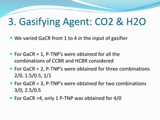
The document discusses thermodynamic analysis of biomass gasification. It analyzes the reaction thermoneutral points (R-TNPs) for gasifying rice husk with different gasifying agents and their ratios. Key findings include:
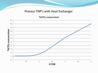
- For CO2 alone, R-TNPs decreased with higher CO2:carbon ratios, with syngas output and CO2 conversion also decreasing. Heat requirements initially rose then fell with a heat exchanger.
- R-TNPs were not found for H2O alone at any ratio.
- With CO2+H2O, R-TNPs were only obtained at low total gasifier agent:carbon ratios. Higher ratios supported


![Introduction
It is assumed that the exit products of the coal gasifier are in
thermodynamic equilibrium.
HSC Chemistry software is well known software that uses
the Gibbs free energy minimization algorithm to find the
equilibrium product composition from a feed mixture and
has been used in gasification studies earlier
[Kumabe K, Hanaoka T, Fujimoto S, Minowa T, Sakanishi K.
Co-gasification of woody biomass and coal with air and
steam. Fuel 2007;86:684–9.]
We have also used HSC Chemistry 5.11 for our calculations](https://image.slidesharecdn.com/aca2354e-f9bd-4469-a69e-66373b727a66-150824093711-lva1-app6892/85/Biomass-Gasification-presentation-4-320.jpg)


![Methodology
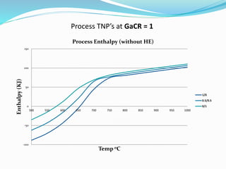
PART B: Process TNP Analysis (without HE)
We calculated the Biomass preheating value for temperatures
between 500 to 1000 °C, with intervals of 50 °C.
Cp value of Rice husk was taken as 2.094 J/gK [Kaupp (1984)]
We then calculated the preheating value of gasifying agents
(CO2 and H2O) for respective temperatures. Cp value of CO2
and H2O was taken from Perry's Chemical Engineers'
Handbook 7e
We then calculated the Process enthalpy (without Heat
Exchanger) as the sum of Reaction enthalpy, Biomass
preheating and Gasifying Agents preheating
(Figure 1)](https://image.slidesharecdn.com/aca2354e-f9bd-4469-a69e-66373b727a66-150824093711-lva1-app6892/85/Biomass-Gasification-presentation-38-320.jpg)