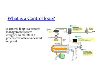
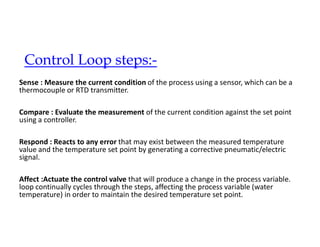
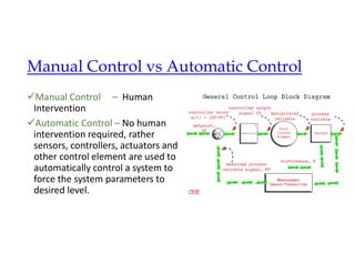
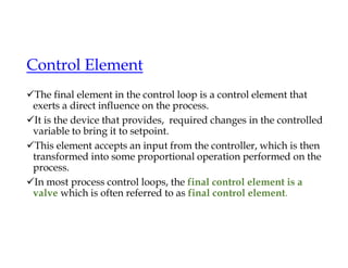
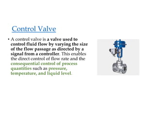
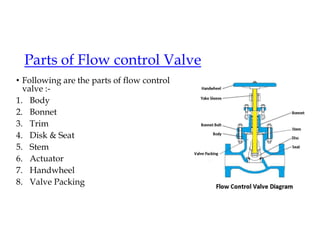
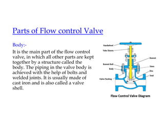
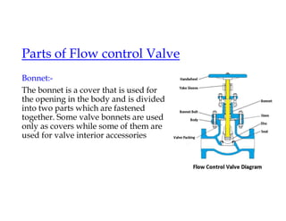
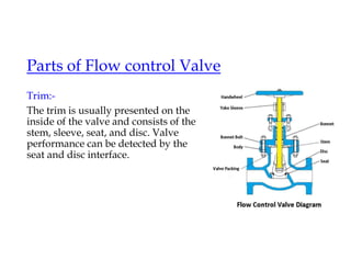
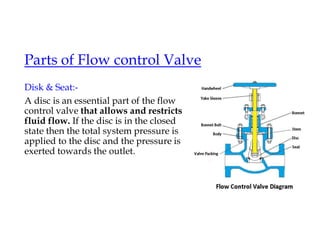
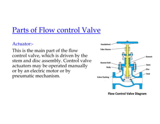
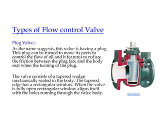
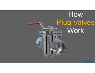
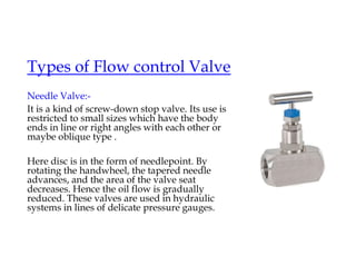
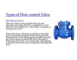
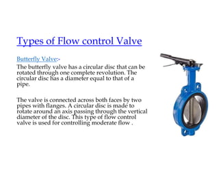
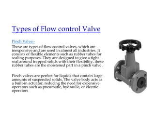
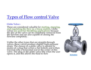
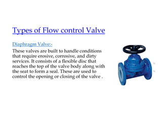
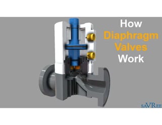
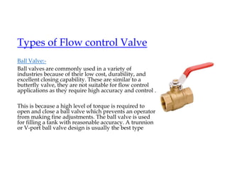
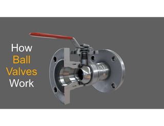
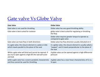
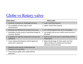
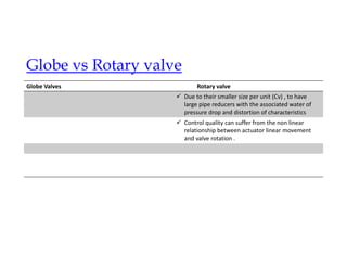
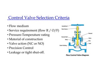
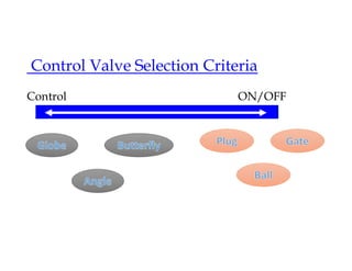
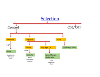
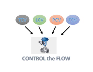
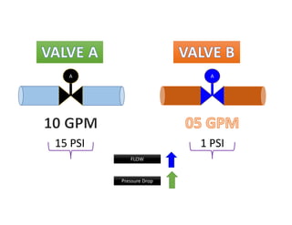
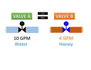
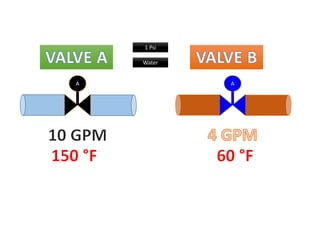
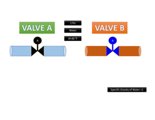
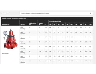
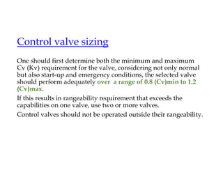
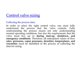
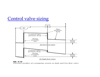
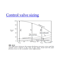
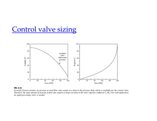
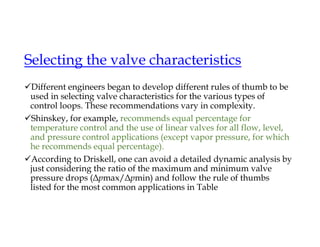
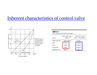
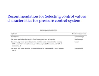
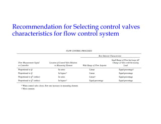
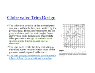
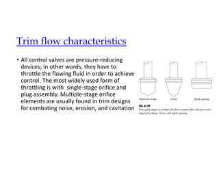
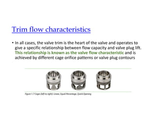
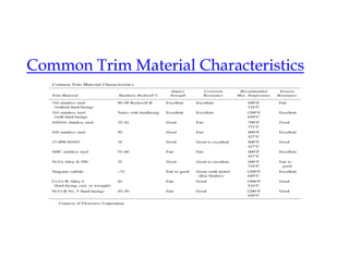
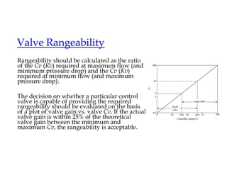
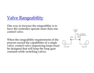
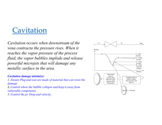
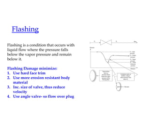
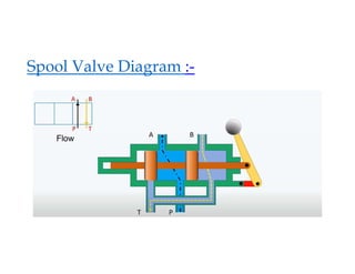
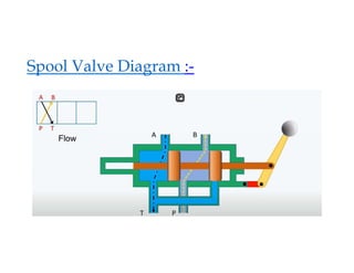
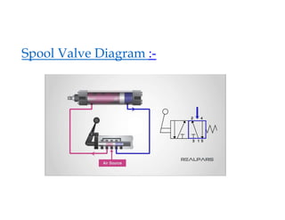
Welcome to the Presentation
on Control valves
(20.05.2024)
By: Bhupesh Kr. Pal
SM (LPG P/L O&M)
Valves-
Introduction to Valves
 Standard Flow
 Normal Flow
 Actual Flow
1 atm (101.3 Kpa or 14.696psia) , 15 C
1 atm (101.3 Kpa or 14.696psia) , 0 C
Process Conditions
Process Conditions
What is a Control loop?
• A control loop is a system made up of all the hardware components
and software control functions needed for the measurement and
adjustment of a variable that controls an individual process
What is a Control loop?
• A control loop is a process management system designed to maintain a process variable at a desired
set point
What is a Control loop?
A control loop is a process
management system
designed to maintain a
process variable at a desired
set point
Control Loop steps:-
Sense : Measure the current condition of the process using a sensor, which can be a
thermocouple or RTD transmitter.
Compare : Evaluate the measurement of the current condition against the set point
using a controller.
Respond : Reacts to any error that may exist between the measured temperature
value and the temperature set point by generating a corrective pneumatic/electric
signal.
Affect :Actuate the control valve that will produce a change in the process variable.
loop continually cycles through the steps, affecting the process variable (water
temperature) in order to maintain the desired temperature set point.
Manual Control vs Automatic Control
Manual Control – Human
Intervention
Automatic Control – No human
intervention required, rather
sensors, controllers, actuators and
other control element are used to
automatically control a system to
force the system parameters to
desired level.
Control Element
The final element in the control loop is a control element that
exerts a direct influence on the process.
It is the device that provides, required changes in the controlled
variable to bring it to setpoint.
This element accepts an input from the controller, which is then
transformed into some proportional operation performed on the
process.
In most process control loops, the final control element is a
valve which is often referred to as final control element.
Control Valve
• A control valve is a valve used to
control fluid flow by varying the size
of the flow passage as directed by a
signal from a controller. This enables
the direct control of flow rate and the
consequential control of process
quantities such as pressure,
temperature, and liquid level.
Parts of Flow control Valve
• Following are the parts of flow control
valve :-
1. Body
2. Bonnet
3. Trim
4. Disk & Seat
5. Stem
6. Actuator
7. Handwheel
8. Valve Packing
Parts of Flow control Valve
Body:-
It is the main part of the flow control
valve, in which all other parts are kept
together by a structure called the
body. The piping in the valve body is
achieved with the help of bolts and
welded joints. It is usually made of
cast iron and is also called a valve
shell.
Parts of Flow control Valve
Bonnet:-
The bonnet is a cover that is used for
the opening in the body and is divided
into two parts which are fastened
together. Some valve bonnets are used
only as covers while some of them are
used for valve interior accessories
Parts of Flow control Valve
Trim:-
The trim is usually presented on the
inside of the valve and consists of the
stem, sleeve, seat, and disc. Valve
performance can be detected by the
seat and disc interface.
Parts of Flow control Valve
Disk & Seat:-
A disc is an essential part of the flow
control valve that allows and restricts
fluid flow. If the disc is in the closed
state then the total system pressure is
applied to the disc and the pressure is
exerted towards the outlet.
Parts of Flow control Valve
Stem:-
These are liable for the connection of
the actuator and the disc, which holds
the disc in position. The connection is
done by the threads and welded joints.
Generally, two types of the stem are
used which are non-rising stem and
rising stem.
Parts of Flow control Valve
Actuator:-
This is the main part of the flow
control valve, which is driven by the
stem and disc assembly. Control valve
actuators may be operated manually
or by an electric motor or by
pneumatic mechanism.
Parts of Flow control Valve
Handwheel:-
It is a simplest type of valve actuator.
A valve handwheel is used to
manually control the opening and
closing of the valve .
Working of Flow control Valve
• The flow of the fluid can be controlled by changing the
place through which it is passing. In this, a pressure
drop occurs and this must be considered when
choosing a flow control valve.
Types of Flow control Valve
1. Gate Valve
2. Plug valve
3. Needle valve
4. Non-return valve
5. Butterfly valve
6. Pressure compensated flow control vlv.
7. Pinch valve
8. Globe valve
9. Diagram valve
Types of Flow control Valve
Gate Valve:-
The valve controls the flow of the liquid in a pipe by
moving a flat plate called a gate or disc valve. Gate is
built perpendicular to the length of the pipe with the
help of a handwheel.
This mechanism is achieved by connecting the gate
with the handwheel through a threaded spindle that
rotates in the valve body. The advantage of a gate
valve is that it offers little or no resistance to flow
when it is fully open. It is usually made up of
gunmetal.
Animation
Types of Flow control Valve
Plug Valve:-
As the name suggests, this valve is having a plug.
This plug can be turned to move its ports to
control the flow of oil and it features to reduce
the friction between the plug face and the body
seat when the turning of the plug.
The valve consists of a tapered wedge
mechanically seated in the body. The tapered
edge has a rectangular window. When the valve
is fully open rectangular window aligns itself
with the holes running through the valve body. Animation
Types of Flow control Valve
Needle Valve:-
It is a kind of screw-down stop valve. Its use is
restricted to small sizes which have the body
ends in line or right angles with each other or
maybe oblique type .
Here disc is in the form of needlepoint. By
rotating the handwheel, the tapered needle
advances, and the area of the valve seat
decreases. Hence the oil flow is gradually
reduced. These valves are used in hydraulic
systems in lines of delicate pressure gauges.
Types of Flow control Valve
Non-Return Valve:-
The non-return valve permits flow in one
direction and stops the flow completely in one
direction. It consists of a valve body, a poppet, a
spring, and a seat.
When the force of fluid is available at the inlet
port exceeds the strength of the spring and the
backpressure of oil the poppet is pushed up and
the valve opens to permit the flow through it.
When the oil is flow is reversed, the valve piston
is pushed back to its seat, completely blocking the
flow.
Types of Flow control Valve
Butterfly Valve:-
The butterfly valve has a circular disc that can be
rotated through one complete revolution. The
circular disc has a diameter equal to that of a
pipe.
The valve is connected across both faces by two
pipes with flanges. A circular disc is made to
rotate around an axis passing through the vertical
diameter of the disc. This type of flow control
valve is used for controlling moderate flow .
Types of Flow control Valve
Pinch Valve:-
These are types of flow control valves, which are
inexpensive and are used in almost all industries. It
consists of flexible elements such as rubber tubes for
sealing purposes. They are designed to give a tight
seal around trapped solids with their flexibility, these
rubber tubes are the moistened part in a pinch valve .
Pinch valves are perfect for liquids that contain large
amounts of suspended solids. The valve body acts as
a built-in actuator, reducing the need for expensive
operators such as pneumatic, hydraulic, or electric
operators
Types of Flow control Valve
Globe Valve:-
These are considered valuable for starting, stopping,
and regulating the flow in a linear motion. Globe
valves are used for throttling applications because
the disc of the valve can be completely removed from
the flowline and are also capable of closing the
flowline completely .
Unlike the other types that are straight-through
valves, these valves produce slightly high-pressure
drops. The closure in a globe valve is opened by
means of a plug that covers a flat bottom and is then
lowered onto a horizontal seat in the center of this
valve. The plug in the globe valve lifts when the user
opens it, and this allows the fluid to flow Animation
Types of Flow control Valve
Diaphragm Valve:-
These valves are built to handle conditions
that require erosive, corrosive, and dirty
services. It consists of a flexible disc that
reaches the top of the valve body along with
the seat to form a seal. These are used to
control the opening or closing of the valve .
Types of Flow control Valve
Ball Valve:-
Ball valves are commonly used in a variety of
industries because of their low cost, durability, and
excellent closing capability. These are similar to a
butterfly valve, they are not suitable for flow control
applications as they require high accuracy and control .
This is because a high level of torque is required to
open and close a ball valve which prevents an operator
from making fine adjustments. The ball valve is used
for filling a tank with reasonable accuracy. A trunnion
or V-port ball valve design is usually the best type
Gate valve Vs Globe Valve
Globe Valve
Gate Valve
Globe valve has very good throttling ability
Gate valve is not used for throttling.
globe valve is best suited for regulating or throttling
the flow
Gate valve is best suited for isolation
Globe valve requires greater torque to operate as
compared to gate valve
Globe valve has flow direction usually indicated on it
Gate valve can have flow in both directions
In a globe valve, the closure element is usually called a
“poppet”, and it travels perpendicular to the plane of
the seat
In a gate valve, the closure element is a plate or disk
which travels parallel to the plane of the seat
A globe valve can be opened against a high differential
pressure
While a gate valve will bind and cannot be opened. If
you try to open against a high DP, the seat will score
and leak
A globe valve has a near linear characteristics of Cv vs.
% open
while a gate valve has a severe parabolic characteristic
and thus cannot be used for throttling.
Globe vs Rotary valve
Rotary valve
Globe Valves
 Lower manufacturing cost
 Simplicity of Spring-and -Diaphragm Actuator
 Higher relative flow capacity
 The availability of wide range of valve
Characteristics
 Cd = 20-40 instead of Cd= 10-15 as for globe.
 Relatively low likelihood of Cavitation and noise
 Less weight and can act as both control and shut –
off valves
 Availability of wide variety of specialized design for
corrosive, abrasive
 Easier to seal at the stem to meet OSHA and EPA
requirement
 Availability for high/low temperature and pressure
application
 Major disadvantage of rotary valves are their
higher tendency to cavitate and to produce
excessive amount of noise.
 Linear relationship between control signal and
valves stem movement
 Relatively small amount of dead band and
hysteresis in its operation
 These features globe valve usable without
positioner
Globe vs Rotary valve
Rotary valve
Globe Valves
 Due to their smaller size per unit (Cv) , to have
large pipe reducers with the associated water of
pressure drop and distortion of characteristics
 Control quality can suffer from the non linear
relationship between actuator linear movement
and valve rotation .
Control valve trends/scenario
During earlier time majority of throttling control valves are
globe valves ; characterized by linear plug movement and
actuated by spring-and diaphragm operators and rotary valves
are considered to be on/off shut-off devices.
Globe valves are still widely used, but their dominance is being
challenged by the less expensive rotary (ball, butter-fly, plug)
valves, which are usually actuated by the cylinder operators.
Control Valve Selection Criteria
• Flow medium
• Service requirement (flow R / O/F)
• Pressure-Temperature rating
• Material of construction
• Valve action (NC or NO)
• Precision Control
• Leakage or tight shut-off.
Control Valve Selection Criteria
Control ON/OFF
Selection
Control ON/OFF
Small Size
Globe
Significant Pr.
Drop is an
issue
2-6”
Large Size
Low DP
~10 bar
Butterfly
Precise
Control not
required
Very High DP
Special Design
Globe valve
Anti
Cavitation
Trim
Slurry
Diaphragm valve
A A
15 PSI 1 PSI
Pressure Drop
FLOW
A A
1 Psi
Water
A A
1 Psi
Water
A A
1 Psi
Water
At 60 °F
Specific Gravity of Water =1
Valve Capacity Coefficient (Cv)
• Cv= No of us gallons of water that can
flow through a valve with 1 psi drop in
pressure at 60 °F for period of 1 minute
• Valve Flow Coefficient (Cv) is the flow
capability of a control valve at fully open
conditions relative to the pressure drop
across the valve.
•
Q = Flow rate (10)
SG = Specific gravity (1)
P = Pressure Drop (0.11)
Cv= 30
Valve Capacity Coefficient (Cv)
Cv= The valve capacity coefficient used here is the Cv, which is unity,
if the valve passes 1.0 GPM of cold water at a specific gravity of 1.0 at a
pressure drop of 1.0 psid.
Kv= The metric equivalent is the Kv, which corresponds to a valve
passing 1 m3 of cold water per hour at a pressure drop of 1 bar.
Cv = 1.17 Kv
Valve Capacity Coefficient (Cv)
• Cv is a tool to compare flow capacity of a valve from
any other valve through out the world.
• It is measure of resistance valve offers to the flow.
• Higher the flow co-coefficient, lower the resistance
to the flow.
Valve Capacity Coefficient (Cv)
• Correct Cv selection is critical for efficient control of
the valve.
If Cv is very Large, the small opening will result in large flow which will
cause poor flow control, and may result in valve or actuators damage in
long run.
If Cv is too small, flow will not be enough to achieve heating or cooling.
Valve Capacity Coefficient (Cv)
Pedal
Speed
100 Km/h
Full Pedal Open %
Cv
50
100 %
Valve Capacity Coefficient (Cv)
Pedal
100 Km/h
Full Pedal Open %
Cv
50
100 %
Max T Norm T Max T
75 Km/h
45 Km/h
30 Km/h
Max Cv
Nor Cv
Min Cv
Rated Cv
Valve Capacity Coefficient (Cv)
Travel % 100 %
Rated Cv
Calculated Cv
80 %
20 %
Cv
Valve Capacity Coefficient (Cv)
Cv chart showing flow
curves for two different
valves: a 2-inch and 3-inch
Kimray back pressure
regulator. As the stem
opens, the CV increases.
The maximum Cv for the 2-
inch valve is 47; the
maximum for the 3-inch
valve is 117
It is recommended to select a valve for which the Cv falls
between 20% and 80% open stem travel.
https://kimray.com/sizing-
calculator/gas-sizing
Control valve sizing
One should first determine both the minimum and maximum
Cv (Kv) requirement for the valve, considering not only normal
but also start-up and emergency conditions, the selected valve
should perform adequately over a range of 0.8 (Cv)min to 1.2
(Cv)max.
If this results in rangeability requirement that exceeds the
capabilities on one valve, use two or more valves.
Control valves should not be operated outside their rangeability.
Control valve sizing
Collecting the process data:
In order to select the right control valve, one must fully
understand the process that the valve controls. Fully
understanding the process means not only understanding
normal operating conditions, but also the requirements that the
valve must live up to during start-up, shutdown, and
emergency conditions. Therefore, all anticipated values of flow
rates, pressures, vapor pressures, densities, temperatures, and
viscosities must be identified in the process of collecting the
data for sizing.
Control valve sizing
Selecting the valve characteristics
Different engineers began to develop different rules of thumb to be
used in selecting valve characteristics for the various types of
control loops. These recommendations vary in complexity.
Shinskey, for example, recommends equal percentage for
temperature control and the use of linear valves for all flow, level,
and pressure control applications (except vapor pressure, for which
he recommends equal percentage).
According to Driskell, one can avoid a detailed dynamic analysis by
just considering the ratio of the maximum and minimum valve
pressure drops (Δpmax/Δpmin) and follow the rule of thumbs
listed for the most common applications in Table
Inherent characteristics of control valve
Linear vs Equal percentage characteristics
Linear characteristics vlv Equal Percentage characteristics vlv
Cv
Opening %
5
10
10
20
15
30
20
40
25
50
30
60
35
70
40
80
45
90
50
100
Cv will inc. by 5 for
every 10% opening
Cv=50
Cv
Opening %
5
10
10
20
20
30
40
40
80
50
160
60
320
70
640
80
1280
90
2560
100
Cv=2560
Cv will inc. by
100% for every
10% opening
Linear vs Equal percentage characteristics
Linear characteristics
•
• Cv = m
• Cv
• But at x =0 , Cv=0
• So C =0
Cv= mx
Equal Percentage characteristics
•
• Cv = m Cv
• Cv = m
• ln =mx+c
Cv = e (mx+c)
Linear vs Equal percentage characteristics
0 5 10 20 40 80
160
320
640
1280
2560
0 10 20 30 40 50 60 70 80 90 100
Equal percentage valve characteristics
0
5
10
15
20
25
30
35
40
45
50
0 10 20 30 40 50 60 70 80 90 100
Linear Valve characteristics
A2
Slide 68
A2 BHUPESH , 14-05-2023
Linear vs Equal percentage characteristics
System ΔP 2.0Bar
10%
(% total system ΔP ) 25% 40%
Valve ΔP (100% open) 0.2 0.5 0.8
Cv 73 42 30
Linear vs Equal percentage characteristics
Min. Value of ΔP
(% of total system)
Linear Equal %
25 10
In most friction system, an increase in load (flow rate) results in drop in the
pressure drop, which is available for the control valve. Therefore the same
amount of increase in flowrate requires a large increase in the valve
capacity coefficient (Cv) for such an application equal percentage valve is
required.
Control Valve Specification
• Data Sheet for reference
Recommendation for Selecting control
valves characteristics for Liquid level
Recommendation for Selecting control valves
characteristics for pressure control system
Recommendation for Selecting control valves
characteristics for flow control system
Globe valve Trim Design
The valve trim consists of the internal parts
contained within the body and wetted by the
process fluid. The main components are the
plug and stem and the seat ring(s). Some
globe valve body designs also incorporate
other parts such as cage or seat retainers,
spacers, guide bushings, and special
elements.
The trim parts create the flow restriction or
throttling action responsible for most of the
pressure loss dissipated in the valve.
The trim design also serves to determine the
inherent flow characteristics of the valve.
• All control valves are pressure-reducing
devices; in other words, they have to
throttle the flowing fluid in order to achieve
control. The most widely used form of
throttling is with single-stage orifice and
plug assembly. Multiple-stage orifice
elements are usually found in trim designs
for combating noise, erosion, and cavitation
Trim flow characteristics
• In all cases, the valve trim is the heart of the valve and operates to
give a specific relationship between flow capacity and valve plug lift.
This relationship is known as the valve flow characteristic and is
achieved by different cage orifice patterns or valve plug contours
Trim flow characteristics
• Control valve manufacturers commonly furnish three types of
inherent characteristic valve trims along with some minor variations
These are idealized curves and do not accurately reflect the actual
characteristic as determined by test. Examination of actual test data
will show deviations in lift vs. flow of 10% or more, slope variations,
and other distortions from the ideal curve
• The typical inherent characteristic (i.e., Cv or Kv vs. lift) test data and
pressure loss vs. flow rate data for the static elements of the process
system can be used to approximate the valve characteristic behavior
in the installed system. This can be used to select the best valve trim
for the controlled process, which will keep the control loop gain
constant or optimized for process control.
Trim flow characteristics
• A traditional rule of thumb is to use a linear trim if the control valve
pressure drop is relatively constant (such as in pure pressure
reducing). Where there is significant system and valve pressure drop
variation as flow changes, the equal percentage trim is
recommended.
Trim flow characteristics
Common Trim Material Characteristics
Rangeability should be calculated as the ratio
of the Cv (Kv) required at maximum flow (and
minimum pressure drop) and the Cv (Kv)
required at minimum flow (and maximum
pressure drop).
The decision on whether a particular control
valve is capable of providing the required
rangeability should be evaluated on the basis
of a plot of valve gain vs. valve Cv. If the actual
valve gain is within 25% of the theoretical
valve gain between the minimum and
maximum Cv, the rangeability is acceptable.
Valve Rangeability
One way to increase the rangeability is to
have the controller operate more than one
control valve.
When the rangeability requirements of the
process exceed the capabilities of a single
valve, control valve sequencing loops must
be designed that will keep the loop gain
constant while switching valves.
Valve Rangeability
Cavitation
Cavitation occurs when downstream of the
vena contracta the pressure rises. When it
reaches the vapor pressure of the process
fluid, the vapor bubbles implode and release
powerful microjets that will damage any
metallic surface in the area.
Cavitation damage minimize:
1. Ensure Plug and seat are made of material that can resist the
damage
2. Control where the bubble collapse and keep it away from
vulnerable components
3. Control the pr. Drop and velocity .
Flashing
Flashing is a condition that occurs with
liquid flow where the pressure falls
below the vapor pressure and remain
below it.
Flashing Damage minimize:
1. Use hard face trim
2. Use more erosion resistant body
material
3. Inc. size of valve, thus reduce
velocity
4. Use angle valve- so flow over plug
Methods to eliminate cavitation
Because no known material can remain indefinitely undamaged
by severe cavitation, the only sure solution is to eliminate
cavitation completely. Even mild cavitation over an extended
time will attack the metal parts upon which the bubbles impinge.
Hard materials survive longer, but they are not an economical
solution except for services with mild intermittent cavitation.
Cavitation damage also varies greatlywith the type of liquid
flowing. The greatest damage is caused by a dense pure liquid
with high surface tension (e.g., water or mercury).
How to avoid cavitation in control valves
Cavitation Solution
Process Parameters Valve Modification
Low cost or no cost Additional cost
Change in Valve Design Stellited Trim Add multiple valves Staged Pressure Drop trim
How to avoid cavitation in control valves
Process Parameters
E
R
R
O
R
(Elevate the pressure)
(Reduce the downstream Pressure)
(Reduce the temp. of fluid)
(Outside gas Injection)
(Recheck the Process I/P)
Actuator Selection
Pneumatic Actuators
Electric Actuators
Digital Actuators
Hydraulic actuators
Actuator Selection
The popularity of the spring-and-diaphragm actuator is due to its low cost, its relatively
high thrust at low air supply pressure, and its availability with “fail-safe” springs. By
trapping the pressure in the diaphragm case, it can also be locked in its last position.
It is available in various designs: springless, double diaphragm (for higher pressures),
rolling diaphragm (for longer strokes), and tandem, which provides more thrust.
One of the limitations of this design is the lack of actuator “stiffness” (resistance to rapidly
varying hydraulic forces caused, for example, by flashing).
For such applications, hydraulic or electromechanical (motor gear) actuators are preferred,
although a stiffer spring (6–30 PSIG, which corresponds to 0.41 to 2.59 bars) in a spring-and-
diaphragm unit is sometimes sufficient to correct the problem.
Positioners
• The positioner is a high-gain plain proportional controller that
measures the valve stem position (to within 0.1 mm), compares
that measurement to its set point (the controller output signal),
and, if there is a difference, corrects the error.
• The open-loop gain of positioners ranges from 10 to 200
(proportional band of 10–0.5%), and their periods of oscillation
range between 0.3 and 10 sec (frequency response of 3–0.1 Hz).
In other words, the positioner is a very sensitively tuned,
proportional-only controller.
When to use positioner
• The main purpose of having a positioner is to guarantee that the
valve does, in fact, move to the position where the controller wants it
to be.
• The addition of a positioner can correct for many variations,
including changes in packing friction due to dirt, corrosion, or lack
of lubrication; variations in the dynamic forces of the process; sloppy
linkages (dead band); or nonlinearities in the valve actuator.
• The dead band of a valve/actuator combination can be as much as
5%; when a positioner is added, it can be reduced to less than 0.5%.
It is the job of the positioner to protect the controlled variable from
being upset by any of the above variations
When not to use positioner
In the case of fast loops, positioners are likely to degrade loop
response, contribute to proportional offsets, and cause limit
cycling (fast flow, liquid pressure, small volume gas pressure
It is recommended not to use positioners if the positioned valve
is slower than the process variable it is assigned to control.
 I to P Convertor
Valve Leakage
• Any flow through a fully closed control valve when exposed to
the operating pressure differentials and temperatures is referred
to as leakage. It is expressed as a cumulative quantity over a
specified time period for tight shut-off designs and as a
percentage of full capacity for conventional control valves.
According to ANSI B16.104, valves are categorized according to
their allowable leakage into six classes.
Valve Leakage
Valve Leakage
Valves are neither tested nor guaranteed for leakage
Class I
Valves are rated to have less than 0.5% leakage.
Class II
Valves are allowed up to 0.1% leakage
Class III
Valves must not leak more than 0.01% of their capacity
Class IV
valves are specified to have a leakage of 5 × 10(−4) ml/min
water flow per inch (25.4 mm) of seat diameter, per 1 psi
(0,0685 bar) differential pressure
Class V
is for soft-seated valves, and leakage is expressed as
volumetric air flow at rated Δp up to 50 psi (3.45 bar).
Class VI
Spool Valve Diagram :-
Thank you

Brief about control valves & their sizing and selection

  • 1.
    Welcome to thePresentation on Control valves (20.05.2024) By: Bhupesh Kr. Pal SM (LPG P/L O&M)
  • 2.
    Valves- Introduction to Valves Standard Flow  Normal Flow  Actual Flow 1 atm (101.3 Kpa or 14.696psia) , 15 C 1 atm (101.3 Kpa or 14.696psia) , 15 C 1 atm (101.3 Kpa or 14.696psia) , 0 C 1 atm (101.3 Kpa or 14.696psia) , 0 C Process Conditions Process Conditions
  • 3.
    What is aControl loop? • A control loop is a system made up of all the hardware components and software control functions needed for the measurement and adjustment of a variable that controls an individual process
  • 4.
    What is aControl loop? • A control loop is a process management system designed to maintain a process variable at a desired set point
  • 5.
    What is aControl loop? A control loop is a process management system designed to maintain a process variable at a desired set point
  • 6.
    Control Loop steps:- Sense: Measure the current condition of the process using a sensor, which can be a thermocouple or RTD transmitter. Compare : Evaluate the measurement of the current condition against the set point using a controller. Respond : Reacts to any error that may exist between the measured temperature value and the temperature set point by generating a corrective pneumatic/electric signal. Affect :Actuate the control valve that will produce a change in the process variable. loop continually cycles through the steps, affecting the process variable (water temperature) in order to maintain the desired temperature set point.
  • 7.
    Manual Control vsAutomatic Control Manual Control – Human Intervention Automatic Control – No human intervention required, rather sensors, controllers, actuators and other control element are used to automatically control a system to force the system parameters to desired level.
  • 8.
    Control Element The finalelement in the control loop is a control element that exerts a direct influence on the process. It is the device that provides, required changes in the controlled variable to bring it to setpoint. This element accepts an input from the controller, which is then transformed into some proportional operation performed on the process. In most process control loops, the final control element is a valve which is often referred to as final control element.
  • 9.
    Control Valve • Acontrol valve is a valve used to control fluid flow by varying the size of the flow passage as directed by a signal from a controller. This enables the direct control of flow rate and the consequential control of process quantities such as pressure, temperature, and liquid level.
  • 11.
    Parts of Flowcontrol Valve • Following are the parts of flow control valve :- 1. Body 2. Bonnet 3. Trim 4. Disk & Seat 5. Stem 6. Actuator 7. Handwheel 8. Valve Packing
  • 12.
    Parts of Flowcontrol Valve Body:- It is the main part of the flow control valve, in which all other parts are kept together by a structure called the body. The piping in the valve body is achieved with the help of bolts and welded joints. It is usually made of cast iron and is also called a valve shell.
  • 13.
    Parts of Flowcontrol Valve Bonnet:- The bonnet is a cover that is used for the opening in the body and is divided into two parts which are fastened together. Some valve bonnets are used only as covers while some of them are used for valve interior accessories
  • 14.
    Parts of Flowcontrol Valve Trim:- The trim is usually presented on the inside of the valve and consists of the stem, sleeve, seat, and disc. Valve performance can be detected by the seat and disc interface.
  • 15.
    Parts of Flowcontrol Valve Disk & Seat:- A disc is an essential part of the flow control valve that allows and restricts fluid flow. If the disc is in the closed state then the total system pressure is applied to the disc and the pressure is exerted towards the outlet.
  • 16.
    Parts of Flowcontrol Valve Stem:- These are liable for the connection of the actuator and the disc, which holds the disc in position. The connection is done by the threads and welded joints. Generally, two types of the stem are used which are non-rising stem and rising stem.
  • 17.
    Parts of Flowcontrol Valve Actuator:- This is the main part of the flow control valve, which is driven by the stem and disc assembly. Control valve actuators may be operated manually or by an electric motor or by pneumatic mechanism.
  • 18.
    Parts of Flowcontrol Valve Handwheel:- It is a simplest type of valve actuator. A valve handwheel is used to manually control the opening and closing of the valve .
  • 20.
    Working of Flowcontrol Valve • The flow of the fluid can be controlled by changing the place through which it is passing. In this, a pressure drop occurs and this must be considered when choosing a flow control valve.
  • 21.
    Types of Flowcontrol Valve 1. Gate Valve 2. Plug valve 3. Needle valve 4. Non-return valve 5. Butterfly valve 6. Pressure compensated flow control vlv. 7. Pinch valve 8. Globe valve 9. Diagram valve
  • 22.
    Types of Flowcontrol Valve Gate Valve:- The valve controls the flow of the liquid in a pipe by moving a flat plate called a gate or disc valve. Gate is built perpendicular to the length of the pipe with the help of a handwheel. This mechanism is achieved by connecting the gate with the handwheel through a threaded spindle that rotates in the valve body. The advantage of a gate valve is that it offers little or no resistance to flow when it is fully open. It is usually made up of gunmetal. Animation
  • 24.
    Types of Flowcontrol Valve Plug Valve:- As the name suggests, this valve is having a plug. This plug can be turned to move its ports to control the flow of oil and it features to reduce the friction between the plug face and the body seat when the turning of the plug. The valve consists of a tapered wedge mechanically seated in the body. The tapered edge has a rectangular window. When the valve is fully open rectangular window aligns itself with the holes running through the valve body. Animation
  • 26.
    Types of Flowcontrol Valve Needle Valve:- It is a kind of screw-down stop valve. Its use is restricted to small sizes which have the body ends in line or right angles with each other or maybe oblique type . Here disc is in the form of needlepoint. By rotating the handwheel, the tapered needle advances, and the area of the valve seat decreases. Hence the oil flow is gradually reduced. These valves are used in hydraulic systems in lines of delicate pressure gauges.
  • 27.
    Types of Flowcontrol Valve Non-Return Valve:- The non-return valve permits flow in one direction and stops the flow completely in one direction. It consists of a valve body, a poppet, a spring, and a seat. When the force of fluid is available at the inlet port exceeds the strength of the spring and the backpressure of oil the poppet is pushed up and the valve opens to permit the flow through it. When the oil is flow is reversed, the valve piston is pushed back to its seat, completely blocking the flow.
  • 28.
    Types of Flowcontrol Valve Butterfly Valve:- The butterfly valve has a circular disc that can be rotated through one complete revolution. The circular disc has a diameter equal to that of a pipe. The valve is connected across both faces by two pipes with flanges. A circular disc is made to rotate around an axis passing through the vertical diameter of the disc. This type of flow control valve is used for controlling moderate flow .
  • 30.
    Types of Flowcontrol Valve Pinch Valve:- These are types of flow control valves, which are inexpensive and are used in almost all industries. It consists of flexible elements such as rubber tubes for sealing purposes. They are designed to give a tight seal around trapped solids with their flexibility, these rubber tubes are the moistened part in a pinch valve . Pinch valves are perfect for liquids that contain large amounts of suspended solids. The valve body acts as a built-in actuator, reducing the need for expensive operators such as pneumatic, hydraulic, or electric operators
  • 32.
    Types of Flowcontrol Valve Globe Valve:- These are considered valuable for starting, stopping, and regulating the flow in a linear motion. Globe valves are used for throttling applications because the disc of the valve can be completely removed from the flowline and are also capable of closing the flowline completely . Unlike the other types that are straight-through valves, these valves produce slightly high-pressure drops. The closure in a globe valve is opened by means of a plug that covers a flat bottom and is then lowered onto a horizontal seat in the center of this valve. The plug in the globe valve lifts when the user opens it, and this allows the fluid to flow Animation
  • 34.
    Types of Flowcontrol Valve Diaphragm Valve:- These valves are built to handle conditions that require erosive, corrosive, and dirty services. It consists of a flexible disc that reaches the top of the valve body along with the seat to form a seal. These are used to control the opening or closing of the valve .
  • 36.
    Types of Flowcontrol Valve Ball Valve:- Ball valves are commonly used in a variety of industries because of their low cost, durability, and excellent closing capability. These are similar to a butterfly valve, they are not suitable for flow control applications as they require high accuracy and control . This is because a high level of torque is required to open and close a ball valve which prevents an operator from making fine adjustments. The ball valve is used for filling a tank with reasonable accuracy. A trunnion or V-port ball valve design is usually the best type
  • 38.
    Gate valve VsGlobe Valve Globe Valve Gate Valve Globe valve has very good throttling ability Gate valve is not used for throttling. globe valve is best suited for regulating or throttling the flow Gate valve is best suited for isolation Globe valve requires greater torque to operate as compared to gate valve Globe valve has flow direction usually indicated on it Gate valve can have flow in both directions In a globe valve, the closure element is usually called a “poppet”, and it travels perpendicular to the plane of the seat In a gate valve, the closure element is a plate or disk which travels parallel to the plane of the seat A globe valve can be opened against a high differential pressure While a gate valve will bind and cannot be opened. If you try to open against a high DP, the seat will score and leak A globe valve has a near linear characteristics of Cv vs. % open while a gate valve has a severe parabolic characteristic and thus cannot be used for throttling.
  • 39.
    Globe vs Rotaryvalve Rotary valve Globe Valves  Lower manufacturing cost  Simplicity of Spring-and -Diaphragm Actuator  Higher relative flow capacity  The availability of wide range of valve Characteristics  Cd = 20-40 instead of Cd= 10-15 as for globe.  Relatively low likelihood of Cavitation and noise  Less weight and can act as both control and shut – off valves  Availability of wide variety of specialized design for corrosive, abrasive  Easier to seal at the stem to meet OSHA and EPA requirement  Availability for high/low temperature and pressure application  Major disadvantage of rotary valves are their higher tendency to cavitate and to produce excessive amount of noise.  Linear relationship between control signal and valves stem movement  Relatively small amount of dead band and hysteresis in its operation  These features globe valve usable without positioner
  • 40.
    Globe vs Rotaryvalve Rotary valve Globe Valves  Due to their smaller size per unit (Cv) , to have large pipe reducers with the associated water of pressure drop and distortion of characteristics  Control quality can suffer from the non linear relationship between actuator linear movement and valve rotation .
  • 41.
    Control valve trends/scenario Duringearlier time majority of throttling control valves are globe valves ; characterized by linear plug movement and actuated by spring-and diaphragm operators and rotary valves are considered to be on/off shut-off devices. Globe valves are still widely used, but their dominance is being challenged by the less expensive rotary (ball, butter-fly, plug) valves, which are usually actuated by the cylinder operators.
  • 42.
    Control Valve SelectionCriteria • Flow medium • Service requirement (flow R / O/F) • Pressure-Temperature rating • Material of construction • Valve action (NC or NO) • Precision Control • Leakage or tight shut-off.
  • 43.
    Control Valve SelectionCriteria Control ON/OFF
  • 44.
    Selection Control ON/OFF Small Size Globe SignificantPr. Drop is an issue 2-6” Large Size Low DP ~10 bar Butterfly Precise Control not required Very High DP Special Design Globe valve Anti Cavitation Trim Slurry Diaphragm valve
  • 46.
    A A 15 PSI1 PSI Pressure Drop FLOW
  • 47.
  • 48.
  • 49.
    A A 1 Psi Water At60 °F Specific Gravity of Water =1
  • 50.
    Valve Capacity Coefficient(Cv) • Cv= No of us gallons of water that can flow through a valve with 1 psi drop in pressure at 60 °F for period of 1 minute • Valve Flow Coefficient (Cv) is the flow capability of a control valve at fully open conditions relative to the pressure drop across the valve. • Q = Flow rate (10) SG = Specific gravity (1) P = Pressure Drop (0.11) Cv= 30
  • 51.
    Valve Capacity Coefficient(Cv) Cv= The valve capacity coefficient used here is the Cv, which is unity, if the valve passes 1.0 GPM of cold water at a specific gravity of 1.0 at a pressure drop of 1.0 psid. Kv= The metric equivalent is the Kv, which corresponds to a valve passing 1 m3 of cold water per hour at a pressure drop of 1 bar. Cv = 1.17 Kv
  • 52.
    Valve Capacity Coefficient(Cv) • Cv is a tool to compare flow capacity of a valve from any other valve through out the world. • It is measure of resistance valve offers to the flow. • Higher the flow co-coefficient, lower the resistance to the flow.
  • 53.
    Valve Capacity Coefficient(Cv) • Correct Cv selection is critical for efficient control of the valve. If Cv is very Large, the small opening will result in large flow which will cause poor flow control, and may result in valve or actuators damage in long run. If Cv is too small, flow will not be enough to achieve heating or cooling.
  • 54.
    Valve Capacity Coefficient(Cv) Pedal Speed 100 Km/h Full Pedal Open % Cv 50 100 %
  • 55.
    Valve Capacity Coefficient(Cv) Pedal 100 Km/h Full Pedal Open % Cv 50 100 % Max T Norm T Max T 75 Km/h 45 Km/h 30 Km/h Max Cv Nor Cv Min Cv Rated Cv
  • 56.
    Valve Capacity Coefficient(Cv) Travel % 100 % Rated Cv Calculated Cv 80 % 20 % Cv
  • 57.
    Valve Capacity Coefficient(Cv) Cv chart showing flow curves for two different valves: a 2-inch and 3-inch Kimray back pressure regulator. As the stem opens, the CV increases. The maximum Cv for the 2- inch valve is 47; the maximum for the 3-inch valve is 117 It is recommended to select a valve for which the Cv falls between 20% and 80% open stem travel. https://kimray.com/sizing- calculator/gas-sizing
  • 59.
    Control valve sizing Oneshould first determine both the minimum and maximum Cv (Kv) requirement for the valve, considering not only normal but also start-up and emergency conditions, the selected valve should perform adequately over a range of 0.8 (Cv)min to 1.2 (Cv)max. If this results in rangeability requirement that exceeds the capabilities on one valve, use two or more valves. Control valves should not be operated outside their rangeability.
  • 60.
    Control valve sizing Collectingthe process data: In order to select the right control valve, one must fully understand the process that the valve controls. Fully understanding the process means not only understanding normal operating conditions, but also the requirements that the valve must live up to during start-up, shutdown, and emergency conditions. Therefore, all anticipated values of flow rates, pressures, vapor pressures, densities, temperatures, and viscosities must be identified in the process of collecting the data for sizing.
  • 61.
  • 62.
  • 63.
  • 64.
    Selecting the valvecharacteristics Different engineers began to develop different rules of thumb to be used in selecting valve characteristics for the various types of control loops. These recommendations vary in complexity. Shinskey, for example, recommends equal percentage for temperature control and the use of linear valves for all flow, level, and pressure control applications (except vapor pressure, for which he recommends equal percentage). According to Driskell, one can avoid a detailed dynamic analysis by just considering the ratio of the maximum and minimum valve pressure drops (Δpmax/Δpmin) and follow the rule of thumbs listed for the most common applications in Table
  • 65.
  • 66.
    Linear vs Equalpercentage characteristics Linear characteristics vlv Equal Percentage characteristics vlv Cv Opening % 5 10 10 20 15 30 20 40 25 50 30 60 35 70 40 80 45 90 50 100 Cv will inc. by 5 for every 10% opening Cv=50 Cv Opening % 5 10 10 20 20 30 40 40 80 50 160 60 320 70 640 80 1280 90 2560 100 Cv=2560 Cv will inc. by 100% for every 10% opening
  • 67.
    Linear vs Equalpercentage characteristics Linear characteristics • • Cv = m • Cv • But at x =0 , Cv=0 • So C =0 Cv= mx Equal Percentage characteristics • • Cv = m Cv • Cv = m • ln =mx+c Cv = e (mx+c)
  • 68.
    Linear vs Equalpercentage characteristics 0 5 10 20 40 80 160 320 640 1280 2560 0 10 20 30 40 50 60 70 80 90 100 Equal percentage valve characteristics 0 5 10 15 20 25 30 35 40 45 50 0 10 20 30 40 50 60 70 80 90 100 Linear Valve characteristics A2
  • 69.
    Slide 68 A2 BHUPESH, 14-05-2023
  • 70.
    Linear vs Equalpercentage characteristics System ΔP 2.0Bar 10% (% total system ΔP ) 25% 40% Valve ΔP (100% open) 0.2 0.5 0.8 Cv 73 42 30
  • 71.
    Linear vs Equalpercentage characteristics Min. Value of ΔP (% of total system) Linear Equal % 25 10
  • 72.
    In most frictionsystem, an increase in load (flow rate) results in drop in the pressure drop, which is available for the control valve. Therefore the same amount of increase in flowrate requires a large increase in the valve capacity coefficient (Cv) for such an application equal percentage valve is required.
  • 73.
    Control Valve Specification •Data Sheet for reference
  • 74.
    Recommendation for Selectingcontrol valves characteristics for Liquid level
  • 75.
    Recommendation for Selectingcontrol valves characteristics for pressure control system
  • 76.
    Recommendation for Selectingcontrol valves characteristics for flow control system
  • 77.
    Globe valve TrimDesign The valve trim consists of the internal parts contained within the body and wetted by the process fluid. The main components are the plug and stem and the seat ring(s). Some globe valve body designs also incorporate other parts such as cage or seat retainers, spacers, guide bushings, and special elements. The trim parts create the flow restriction or throttling action responsible for most of the pressure loss dissipated in the valve. The trim design also serves to determine the inherent flow characteristics of the valve.
  • 78.
    • All controlvalves are pressure-reducing devices; in other words, they have to throttle the flowing fluid in order to achieve control. The most widely used form of throttling is with single-stage orifice and plug assembly. Multiple-stage orifice elements are usually found in trim designs for combating noise, erosion, and cavitation Trim flow characteristics
  • 79.
    • In allcases, the valve trim is the heart of the valve and operates to give a specific relationship between flow capacity and valve plug lift. This relationship is known as the valve flow characteristic and is achieved by different cage orifice patterns or valve plug contours Trim flow characteristics
  • 80.
    • Control valvemanufacturers commonly furnish three types of inherent characteristic valve trims along with some minor variations These are idealized curves and do not accurately reflect the actual characteristic as determined by test. Examination of actual test data will show deviations in lift vs. flow of 10% or more, slope variations, and other distortions from the ideal curve • The typical inherent characteristic (i.e., Cv or Kv vs. lift) test data and pressure loss vs. flow rate data for the static elements of the process system can be used to approximate the valve characteristic behavior in the installed system. This can be used to select the best valve trim for the controlled process, which will keep the control loop gain constant or optimized for process control. Trim flow characteristics
  • 81.
    • A traditionalrule of thumb is to use a linear trim if the control valve pressure drop is relatively constant (such as in pure pressure reducing). Where there is significant system and valve pressure drop variation as flow changes, the equal percentage trim is recommended. Trim flow characteristics
  • 82.
    Common Trim MaterialCharacteristics
  • 83.
    Rangeability should becalculated as the ratio of the Cv (Kv) required at maximum flow (and minimum pressure drop) and the Cv (Kv) required at minimum flow (and maximum pressure drop). The decision on whether a particular control valve is capable of providing the required rangeability should be evaluated on the basis of a plot of valve gain vs. valve Cv. If the actual valve gain is within 25% of the theoretical valve gain between the minimum and maximum Cv, the rangeability is acceptable. Valve Rangeability
  • 84.
    One way toincrease the rangeability is to have the controller operate more than one control valve. When the rangeability requirements of the process exceed the capabilities of a single valve, control valve sequencing loops must be designed that will keep the loop gain constant while switching valves. Valve Rangeability
  • 85.
    Cavitation Cavitation occurs whendownstream of the vena contracta the pressure rises. When it reaches the vapor pressure of the process fluid, the vapor bubbles implode and release powerful microjets that will damage any metallic surface in the area. Cavitation damage minimize: 1. Ensure Plug and seat are made of material that can resist the damage 2. Control where the bubble collapse and keep it away from vulnerable components 3. Control the pr. Drop and velocity .
  • 86.
    Flashing Flashing is acondition that occurs with liquid flow where the pressure falls below the vapor pressure and remain below it. Flashing Damage minimize: 1. Use hard face trim 2. Use more erosion resistant body material 3. Inc. size of valve, thus reduce velocity 4. Use angle valve- so flow over plug
  • 87.
    Methods to eliminatecavitation Because no known material can remain indefinitely undamaged by severe cavitation, the only sure solution is to eliminate cavitation completely. Even mild cavitation over an extended time will attack the metal parts upon which the bubbles impinge. Hard materials survive longer, but they are not an economical solution except for services with mild intermittent cavitation. Cavitation damage also varies greatlywith the type of liquid flowing. The greatest damage is caused by a dense pure liquid with high surface tension (e.g., water or mercury).
  • 88.
    How to avoidcavitation in control valves Cavitation Solution Process Parameters Valve Modification Low cost or no cost Additional cost Change in Valve Design Stellited Trim Add multiple valves Staged Pressure Drop trim
  • 89.
    How to avoidcavitation in control valves Process Parameters E R R O R (Elevate the pressure) (Reduce the downstream Pressure) (Reduce the temp. of fluid) (Outside gas Injection) (Recheck the Process I/P)
  • 91.
    Actuator Selection Pneumatic Actuators ElectricActuators Digital Actuators Hydraulic actuators
  • 92.
    Actuator Selection The popularityof the spring-and-diaphragm actuator is due to its low cost, its relatively high thrust at low air supply pressure, and its availability with “fail-safe” springs. By trapping the pressure in the diaphragm case, it can also be locked in its last position. It is available in various designs: springless, double diaphragm (for higher pressures), rolling diaphragm (for longer strokes), and tandem, which provides more thrust. One of the limitations of this design is the lack of actuator “stiffness” (resistance to rapidly varying hydraulic forces caused, for example, by flashing). For such applications, hydraulic or electromechanical (motor gear) actuators are preferred, although a stiffer spring (6–30 PSIG, which corresponds to 0.41 to 2.59 bars) in a spring-and- diaphragm unit is sometimes sufficient to correct the problem.
  • 93.
    Positioners • The positioneris a high-gain plain proportional controller that measures the valve stem position (to within 0.1 mm), compares that measurement to its set point (the controller output signal), and, if there is a difference, corrects the error. • The open-loop gain of positioners ranges from 10 to 200 (proportional band of 10–0.5%), and their periods of oscillation range between 0.3 and 10 sec (frequency response of 3–0.1 Hz). In other words, the positioner is a very sensitively tuned, proportional-only controller.
  • 94.
    When to usepositioner • The main purpose of having a positioner is to guarantee that the valve does, in fact, move to the position where the controller wants it to be. • The addition of a positioner can correct for many variations, including changes in packing friction due to dirt, corrosion, or lack of lubrication; variations in the dynamic forces of the process; sloppy linkages (dead band); or nonlinearities in the valve actuator. • The dead band of a valve/actuator combination can be as much as 5%; when a positioner is added, it can be reduced to less than 0.5%. It is the job of the positioner to protect the controlled variable from being upset by any of the above variations
  • 95.
    When not touse positioner In the case of fast loops, positioners are likely to degrade loop response, contribute to proportional offsets, and cause limit cycling (fast flow, liquid pressure, small volume gas pressure It is recommended not to use positioners if the positioned valve is slower than the process variable it is assigned to control.  I to P Convertor
  • 96.
    Valve Leakage • Anyflow through a fully closed control valve when exposed to the operating pressure differentials and temperatures is referred to as leakage. It is expressed as a cumulative quantity over a specified time period for tight shut-off designs and as a percentage of full capacity for conventional control valves. According to ANSI B16.104, valves are categorized according to their allowable leakage into six classes.
  • 97.
  • 98.
    Valve Leakage Valves areneither tested nor guaranteed for leakage Class I Valves are rated to have less than 0.5% leakage. Class II Valves are allowed up to 0.1% leakage Class III Valves must not leak more than 0.01% of their capacity Class IV valves are specified to have a leakage of 5 × 10(−4) ml/min water flow per inch (25.4 mm) of seat diameter, per 1 psi (0,0685 bar) differential pressure Class V is for soft-seated valves, and leakage is expressed as volumetric air flow at rated Δp up to 50 psi (3.45 bar). Class VI
  • 99.
  • 100.
  • 101.
  • 102.
  • 104.