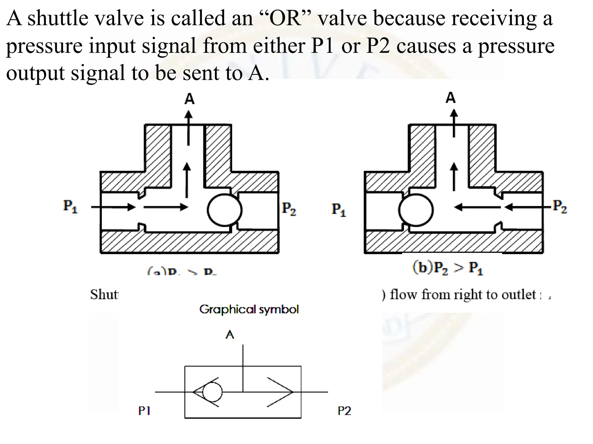
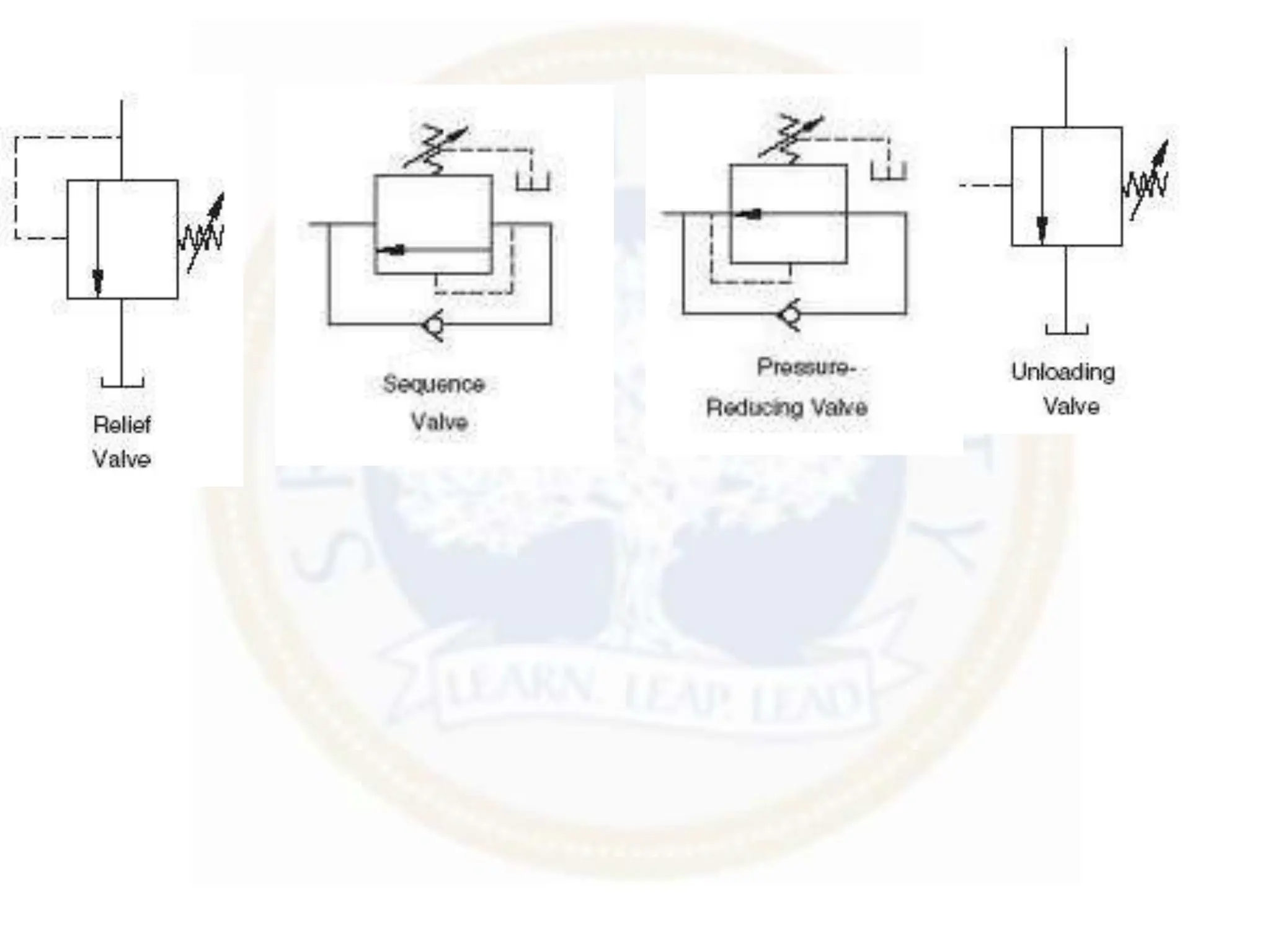
SlideShare a Scribd company logo
1 of 142
CONTROL VALVES
III Year VI Sem
Department of Mechanical Engineering
SRM UNIVERSITY
In fluid power, controlling elements are called valves.
There are three types of valves:
1.Directional control valves (DCVs): They determine the
path through which a fluid transverses a given circuit.
2.Pressure control valves: They protect the system against
overpressure, which may occur due to a sudden surge as
valves open or close or due to an increase in fluid demand.
3. Flow control valves: . the fluid flow rate must be
controlled in various lines of a hydraulic circuit.
It is important to know the primary function and operation of various
types of control components not only for good functioning of a system,
but also for discovering innovative methods to improve the fluid power
system for a given application.
DIRECTIONAL CONTROL VALVES
A valve is a device that receives an external signal
(mechanical, fluid pilot signal, electrical or electronics) to
release, stop or redirect the fluid that flows through it.
The function of a DCV is to control the direction of fluid flow
in any hydraulic / Pneumatic system
A DCV does this by changing the position of internal movable
parts.
A DCV is mainly required for the following purposes:
• To start, stop, accelerate, decelerate and change the direction of
motion of a hydraulic actuator.
• To permit the free flow from the pump to the reservoir at low
pressure when the pump’s delivery is not needed into the system.
•To vent the relief valve by either electrical or mechanical control.
Any valve contains ports that are external openings through
which a fluid can enter and exit via connecting pipelines.
The number of ports on a DCV is identified using the term
“way.” Thus, a valve with four ports is a four-way valve.
A DCV consists of a valve body or valve housing and a valve
mechanism usually mounted on a sub-plate.
The ports of a sub-plate are threaded to hold the tube fittings
which connect the valve to the fluid conductor lines.
The valve mechanism directs the fluid to selected output ports
or stops the fluid from passing through the valve.
i)Classification of DCVs based Fluid Path
• Check valves.
• Shuttle valves.
• Two-way valves.
• Three-way valves.
• Four-way valves. and Five way valves
ii)Classification of DCVs based on Design Characteristics
• An internal valve mechanism that directs the flow of fluid.
(such a mechanism can either be a poppet, a ball, a sliding
spool, a rotary plug or a rotary disk).
•Number of switching positions (usually 2 or 3).
• Number of connecting ports or ways.
• Method of valve actuation that causes the valve mechanism
to move into an alternate position.
iii)Classification of DCVs based on the Actuation Method
Mechanical Actuation
Manual Actuation,
pilot operated and solenoid
iv)Classification of DCVs based on the Construction of
Internal Moving Parts
•Rotary spool type: In this type, the spool is rotated to change
the direction of fluid. It has longitudinal grooves. The rotary
spools are usually manually operated.
• Sliding spool type: This consists of a specially shaped spool
and a means of positioning the spool.
Check valve
Check valve
Free flow in one direction and restricted flow in
Other direction
Check valve
Pilot operated Check valve
Free flow in one direction
Permits flow in other direction if pilot pressure
is ON
Shuttle Valve
A shuttle valve allows two alternate flow sources to be
connected in a one-branch circuit.
The valve has two inlets P1 and P2 and one outlet A.
Outlet A receives flow from an inlet that is at a higher
pressure..
If the pressure at P1 is greater than that at P2, the ball slides to
the right and allows P1 to send flow to outlet A.
If the pressure at P2 is greater than that at P1, the ball slides to
the left and P2 supplies flow to outlet A .
One application for a shuttle valve is to have a primary pump
inlet P1 and a secondary pump inlet P2 connected to the
system outlet A The secondary pump acts as a backup,
supplying flow to the system if the primary pump loses
pressure.
A shuttle valve is called an “OR” valve because receiving a
pressure input signal from either P1 or P2 causes a pressure
output signal to be sent to A.
SPOOL
A cylindrical component on which film, thread, or
other flexible materials can be wound.
A modified spool used
in fluid power valves.
This spool at times
allows and blocks the
fluid flow between ports
2/2 DCV
3/2 DCV
4/2 DCV
4/2 DCV
5/2 DCV
ACTUATING DEVICES
Actuation is the method of moving the valve element from one position
to another. There are four basic methods of actuation: Manual,
mechanical, solenoid-operated and pilot-operated. Several combinations
of actuation are possible using these four basic methods.
Manually operated: In manually operated DCVs, the spool is shifted
manually by moving a handle pushing a button or stepping on a foot
pedal. When the handle is not operated, the spool returns to its original
position by means of a spring.
Mechanically operated: The spool is shifted by mechanical linkages
such as cam and rollers.
Solenoid operated: When an electric coil or a solenoid is energized, it
that pulls the armature into the coil. This causes the armature to push the
spool of the valve.
Pilot operated: A DCV can also be shifted by applying a pilot signal
(either hydraulic or pneumatic) against a piston at either end of the valve
spool. When pilot pressure is introduced, it pushes the piston to shift the
spool.
Rotary Four-way valve
Pressure Control Valve
Pressure-control valves are used in hydraulic systems to
control actuator force (force = pressure × area) and to
maintain a safer pressure levels
Pressure controls are mainly used to perform the following
system functions:
Limiting maximum system pressure at a safe level.
Regulating/reducing pressure in certain portions of the
circuit.
Any pressure-related function
Pressure Control Valve
• Pressure relief valve
• Sequence valve
• Compound pressure relief valve
• Pressure reducing valve
• Unloading valve
• Counterbalance valve
Pressure relief valve
• Pressure-relief valves limit the maximum
pressure in a hydraulic circuit by providing an
alternate path for fluid flow when the
pressure reaches a preset level.
• All circuits require a relief valve to protect
the system from excess pressure.
• In a hydraulic circuit, a relief valve opens and
bypasses fluid when pressure exceeds its
setting.
Cont..
• It is normally a closed valve whose function is to
limit the pressure to a specified maximum value
by diverting pump flow back to the tank.
• A poppet is held seated inside the valve by a
heavy spring.
• When the system pressure reaches a high enough
value, the poppet is forced off its seat.
• This permits flow through the outlet to the tank as
long as this high pressure level is maintained.
• Note the external adjusting screw, which varies
spring force and, thus, the pressure at which the
valve begins to open (cracking pressure).
The pressure that exists at full
pump flow can be substantially
greater than cracking pressure. The
pressure at full pump flow is the
pressure level that is specified
when referring to the pressure
setting of the valve. It is the
maximum pressure level permitted
by the relief valve.
Compound pressure relief valve
• It consists of two relief valve one is pilot relief
valve and other is main pressure relief valve
• It operates in two stages process
first the pilot relief valve opens then
main relief valve opens
Cont..
• It consists of a pressure port connected to
pump and tank port connected to tank
• The main relief valve consists of a piston and a
stem, it has an orifice drilled to it
• The piston in the main relief valve is exposed
to equal force on both sides of the piston
• When a high pressure drop is induced across
the piston due to orifice, it causes the piston
to move upwards from the seat
Advantage over simple pressure relief valve :
For higher pressure settings the size of the
compound pressure valve is smaller than the
simple pressure relief valve
Pressure-Reducing Valve
This valve (which is normally open) is used to maintain
reduced pressures in specified locations of hydraulic systems.
It is actuated by downstream pressure and tends to close as
this pressure reaches the valve setting.
It uses a spring-loaded spool to control the downstream
pressure.
If the downstream pressure is below the valve setting, the
fluid flows freely from the inlet to the outlet.
When the outlet (downstream) pressure increases to the valve
setting, the spool moves to the right to partially block the
outlet port.
Just enough flow is passed to the outlet to maintain its preset
pressure level.
To prevent the outlet port from being complete closed, a
continuous bleed to the tank is permitted via a separate drain
line to the tank.
Application of Pressure reducing valve
GRAPHICAL SYMBOL
A reducing valve is normally
open.
It reads the downstream
pressure.
It has an external drain.
This is represented by a line
connected from the valve
drain port to the tank.
The symbol shows that the
spring cavity has a drain to the
tank.
Unloading Valve
Cont..
• They are pressure-control devices that are used
to dump excess fluid to the tank at little or no
pressure.
• A common application is in high-low pressure
pump circuits where two pumps move an
actuator.
• The circuit then shifts to a single pump
providing a high pressure to perform work.
Application of Unloading valve in
punching operation
• The circuit that uses a high-pressure pump in conjunction with a low-
pressure pump.
• In a punching press, the hydraulic cylinder must extend rapidly over a
great distance with low-pressure, high-flow requirements. This rapid
extension of cylinder occurs under no external load (when the
punching tool approaches the sheet metal).
• But during punching operation for short motion, the pressure
requirements are high due to punching load. During this cylinder
travel, high-pressure, low-flow requirements are needed.
• When punching operation begins, the increased pressure opens the
unloading valve to unload the low-pressure pump.
• The check valve protects the low-pressure pump from high pressure,
which occurs during punching operation that occurs at the end of
cylinder extension.
Pressure Sequence Valve
A sequence valve is a pressure-control valve that is used to
force two actuators to operate in sequence. They are similar to
pressure-relief valves.
Instead of sending flow back to the tank, a sequence valve
allows flow to a branch circuit, when a preset pressure is
reached.
The check valve allows the sequence valve to be bypassed in
the reverse direction.
The sequence valve has an external drain line; therefore, a line
must be connected from the sequence valve’s drain port to the
tank.
A – Upstream B – Downstream
Application of Sequence valve
• In this circuit, two cylinders are connected in parallel.
Without the sequence valve, these cylinders would extend
together as they are both unloaded.
• In order for this circuit to function properly, the clamp
cylinder must extend completely before the bending
cylinder begins to extend.
• The sequence valve accomplishes this by not allowing
flow into the bending cylinder branch of circuit until the
clamp cylinder has reached the end of its stroke.
• When the clamp cylinder extends completely, the pressure
rises and opens the sequence valve, thus allowing the
bending cylinder to extend.
• The sequence valve pressure must be set high enough so
that it opens only after the complete extension of the clamp
cylinder.
Counterbalance Valve
• These normally closed valves are primarily used on a
vertical cylinder to prevent it from falling due to gravity.
They are used to prevent a load from accelerating
uncontrollably.
• The valve primary port is connected to the cylinder rod
end and the secondary port to the directional control
valve. The pressure setting is slightly higher than that
required to keep the load from free-falling.
• When the pressurized fluid flows to the cylinder piston
end, the cylinder extends, increasing pressure in the rod
end and shifting the main spool in the counterbalance
valve.
• This creates a path that permits the fluid to
flow through the secondary port via the
directional control valve and to the reservoir.
As the load is raised, the integral check valve
opens to allow the cylinder to retract freely.
Application of Counter Balance Valve
• To prevent acceleration of cylinder under
vertical load
Problems in Pressure relief valve
• A pressure relief valve contains a poppet with a
4.20 cm2 area on which system pressure acts.
During assembly a spring with spring constant
of 3200 N/ cm is installed in the valve to hold
the poppet against its seat. The adjustment
mechanism is then set so that the spring is
initially compressed 0.50 cm from its free
length condition. In order to pass full pump
flow through the valve at the PRV pressure
setting , the poppet must move 0.30 cm from
its fully closed position. Determine
• a. Cracking pressure
• b. Full pump flow pressure
Flow-control valves
• Control the rate of flow of a fluid to the actuators
• This provide speed control of linear actuators and rotary
actuators.
• Applications include regulating cutting tool speeds, spindle
speeds, surface grinder speeds, and the travel rate of
vertically supported loads moved upward and downward
by forklifts, and dump lifts.
• Flow-control valves also allow one fixed displacement
pump to supply two or more branch circuits fluid at
different flow rates
Functions of Flow-Control Valves
1. Regulate the speed of linear and rotary actuators
Velocity of piston (Vp) (m/s) =
2. Regulate the power available by controlling the flow to
them
Power (W) = Flow rate (m3/s) ×Pressure (N/m2)
Flow-control valves can be classified as follows:
1. Non-pressure compensated valve
2. Pressure compensated valve
Non-pressure compensated flow
control valve
Symbol :
Symbol :
• Non pressure compensated valve is used only
when the variation in the working load is very
less
• When the working load varies heavily then the
outlet pressure of the valve also increases,
non- pressure compensated valve does not
serve the purpose
• To overcome the difficulty we have
Pressure compensated flow control
valve
Cont…
• A pressure-compensated flow-control valve consists of a
main spool and a compensator spool.
• The adjustment knob controls the main spool’s position,
which controls the orifice size at the outlet.
• The upstream pressure is delivered to the valve by the pilot
line A. Similarly, the downstream pressure is ported to the
right side of the compensator spool through the pilot line B.
• The compensator spring pushes the spool so that it tends
toward the fully open position.
• If the pressure drop across the valve increases, that is, the
upstream pressure increases relative to the downstream
pressure, the compensator spool moves to the right against
the force of the spring. This reduces the flow that in turn
reduces the pressure drop and tries to attain a normal flow
• Graphical Symbol for pressure compensated
valve is
Flow rate from flow control valve
Q = Cv *√(
Δ𝑃
𝑆𝐺
)
Q – FLOW RATE (Lpm)
Cv – flow co.eff ( Lpm / √𝑃𝑎)
ΔP- pressure drop (Pa)
SG – specific gravity of oil
problem
• A needle valve is used to control the extending speed of the
hydraulic cylinder. The needle valve is placed in the outline of
the hydraulic cylinder. The following data are given
Desired cylinder speed – 25 cm/sec
Cylinder piston diameter – 5 cm
Cylinder rod diameter – 2.6 cm
Cylinder load – 4.5 kN
Specific gravity of oil – 0.90
PRV settings – 34 bar
Determine the flow coefficient of the needle valve
Servo Valves
• Thesevalveshaveinfinitelyvariablepositioningcapability
• Itcontrolsdirectionoffluidflowaswellastheamount
• Servovalvesarecoupledwithfeedbacksensingdeviceswhichallowforthe
veryaccuratecontrolofposition,velocityandaccelerationofanactuator
• Servovalvesareappropriateforsystemswithoneormoreofthefollowing
characteristics: high load stiffness (static or dynamic); high accuracy and
stability; precise positioning; fine control of velocity and acceleration
control.
Mechanical type servo valves
• Itisaforceamplifierusedforpositioningcontrol
• Inthisvalve,asmallinputforceshiftsthespoolto
therightbyaspecifiedamount
• Theoilthenflowsthroughportp1,thenretracting
thecylinder
• The feedback link shifts the sliding sleeve to the
right until it blocks off the flow to the hydraulic
cylinder
• Thusagiveninputmotionproducesaspecificand
controlledamountofoutputmotion.
• Suchasystemiscalled“closedloopsystem”
• Application :hydraulic power steering system of
automobilesandothertransportationvehicles
Electrohydraulic servo valves
• It uses an electrical torque motor, a
double acting nozzle pilot stage, and a
slidingspoolsecondstage.
• It is an electrically controlled
,proportionalmeteringvalve suitable for
variety of mobile vehicles and industrial
control applications such as earth
moving vechicles,articulated arm
devices, cargo handling cranes, lift
trucks, logging equipment, farm
machinery, steel mill controls, utility
construction, fire trucks and servicing
vehicles.
Electrohydraulic servo valves
• Torquemotorincludescoils,polepieces,magnetsandanarmature.
• The valve directs the flow from the supply pressure port to either of the
twooutletportsinanamountproportionaltospooldisplacement.
• The spool contains the flow metering slots in the control lands that are
uncoveredbyspoolmotion.
• Spool movement deflects a feedback wire that applies a torque to the
armature/flapper
• Electrical current in a torque motor coil causes either clockwise or
anticlockwise torque on an armature to control the movement of the
spool.
• The spool continues to move until the feedback torque counteracts the
electromagnetictorque
• Atthispointthearmature/flapperisreturnedtocenter,sothespoolstops
and remains displaced until the electrical input changes to a new
level,thereforevalvespoolpositionisproportionaltotheelectricalsignal.
Block diagram of Servo valve
Proportional control valves
• Also called electrohydraulic proportional valves-
electricallycontrolled
• Theseareusedinopenloopsystems.
• Here,itusesasolenoidthatproducesaforceproportional
tothecurrentinitscoils
• Thus by controlling the current in the solenoid coil the
positionofthespringloadedspoolcanalsobecontrolled.
• This can provide both directional and flow control
capabilityinasinglevalve
• Itiswidelyusedbecauseitalsocontrolsthepressure.
• Ordinary solenoid valve
Proportional control valve
Pressure Intensifier / Booster
• During punching operation, it requires low pressure
for the initial stroke length
• high pressure oil is needed during the working
stroke(punching)for short period of time
• Some manufacturers make high-pressure rotary
pumps — rated up to approximately > 690 bar—
but these pumps are expensive and may heat the
fluid.
• Another choice for small-volume high-pressure
circuits is an intensifier.
INTENSIFIER / BOOSTER
Cont..
• When a circuit calls for a small volume of high-
pressure oil or air, consider using an intensifier —
sometimes called a booster.
• Diagram for pressure intensifier is shown below
Let
• P1 – air input pressure
• P2 – oil exit pressure
• d1 – large piston diameter
• d2 – smaller piston diameter
• Force acting will be same
• Pressure ratio or area ratio = P2 / P1
Intensifier circuit application
Working cylinder advances at low
pressure
Working cylinder punches at
high pressure
Working cylinder retracts at low
pressure
Air to Air Intensifier
Problems in intensifier
• An air hydraulic intensifier is connected to a hydraulic
cylinder driving a 54 kN load. Diameter of hydraulic cylinder
piston is 38 mm. Following are the data for intensifier
air is supplied at 5 bar pressure
air piston diameter – 203 mm
oil piston diameter – 25 mm
intensifier stroke – 51 mm
intensifier cycle frequency – 1 stroke / sec
Determine
a. Movement of hydraulic cylinder per intensifier stroke
b. pressure developed from the oil piston
ACCUMULATOR
ACCUMULATOR
• An accumulator is device that stores hydraulic
potential energy by means of either gravity,
mechanical spring, or compressed gases.
• The stored potential energy in the
accumulator is a quick secondary source of
fluid power capable of doing useful work as
required by the system.
Types of Accumulator
• Weight loaded, or gravity
• Spring-loaded
• Gas- loaded
Weight loaded
Spring-loaded
• Non separator type
• Separator type
Gas- Loaded
Non Separator type
Separator type
• Piston type
• Diaphragm type
• Bladder type
Gas- loaded
Piston type
Diaphragm type
Bladder type
Basic Applications of Accumulator
• An auxiliary power source
• A leakage compensator
• An emergency power supply
• A hydraulic shock absorber
An auxiliary power source
A leakage compensator
Pressure
Switch
An emergency power supply
ACCUMULATOR AS SHOCK ABSORBER
Operation of a gas loaded accumulator
Notations
• Let
P1 – gas precharge pressure
P2 – maximum pressure
P3 – minimum pressure after discharging
V1 – initial volume during gas precharging
V2 – compressed volume of gas
V3 – expanded volume of gas after oil discharge
V2 – V3 = ?
Volume of oil enters the hydraulic cylinder
Problem
• What is the size of the accumulator required to
supply 5 litres of oil to the cylinder with an
allowable pressure of 210 bar to 105 bar. The
precharge pressure is 70 bar.
• Solve the problem by assuming
a. Charging and discharging to be isothermal
PV = c
a. Charging and discharging to be adiabatic
PVn = c
Accessories in Hydraulic Systems
• Accessories are
Conductors and Fittings
Seals
Heat Exchangers
Conductors & Fittings
• steel tubes, plastic tubes Flexible hoses
• Selection of conductors depends on operating
pressure and flow rate
• It not a good idea to connect steel tubes to
the pump
Sealing Devices
• Efficiency and power loss will occur, if there is
any oil leakage in the system
• Due to wear between mating parts, clearance
increases results in more leakage
• To prevent excessive leakage, SEALS are used
Sealing
Most Widely used type of seals
• O-rings
• Compression packed (V and U- shape)
• Piston rings
• Wiper rings
O-rings
Extrusion of O rings
Compression ring / back up ring (V and
U- shape)
Piston rings
Switches
3 valve shafts pneumatics and hydraulics

More Related Content

Similar to 3 valve shafts pneumatics and hydraulics

chter 3 actuators.pdffejvrvfdvkceckevsvd
chter 3 actuators.pdffejvrvfdvkceckevsvdchter 3 actuators.pdffejvrvfdvkceckevsvd
chter 3 actuators.pdffejvrvfdvkceckevsvd
AdugnaGosa1
 
Unit-3.pdf mechanical enginnering hydraulics
Unit-3.pdf mechanical enginnering hydraulicsUnit-3.pdf mechanical enginnering hydraulics
Unit-3.pdf mechanical enginnering hydraulics
MuditK4
 

Similar to 3 valve shafts pneumatics and hydraulics (20)

chter 3 actuators.pdffejvrvfdvkceckevsvd
chter 3 actuators.pdffejvrvfdvkceckevsvdchter 3 actuators.pdffejvrvfdvkceckevsvd
chter 3 actuators.pdffejvrvfdvkceckevsvd
 
Hydraulic Valves and Hydraulic System Accessories
Hydraulic Valves and Hydraulic System AccessoriesHydraulic Valves and Hydraulic System Accessories
Hydraulic Valves and Hydraulic System Accessories
 
spool actuation method
spool actuation methodspool actuation method
spool actuation method
 
1_Control Valves.ppt
1_Control Valves.ppt1_Control Valves.ppt
1_Control Valves.ppt
 
Unit-3.pdf mechanical enginnering hydraulics
Unit-3.pdf mechanical enginnering hydraulicsUnit-3.pdf mechanical enginnering hydraulics
Unit-3.pdf mechanical enginnering hydraulics
 
Control Valve.pdf
Control Valve.pdfControl Valve.pdf
Control Valve.pdf
 
Control Valves .pdf
Control Valves .pdfControl Valves .pdf
Control Valves .pdf
 
Pressure control valves
Pressure control valvesPressure control valves
Pressure control valves
 
Hydraulic Circuit Contents..pptx
Hydraulic Circuit Contents..pptxHydraulic Circuit Contents..pptx
Hydraulic Circuit Contents..pptx
 
DIRECTION CONTROL VALVE
DIRECTION CONTROL VALVEDIRECTION CONTROL VALVE
DIRECTION CONTROL VALVE
 
Pneumatics: Shuttle, Twin pressure, Quick Exhaust, Time Delay, FRL
Pneumatics: Shuttle, Twin pressure, Quick Exhaust, Time Delay, FRLPneumatics: Shuttle, Twin pressure, Quick Exhaust, Time Delay, FRL
Pneumatics: Shuttle, Twin pressure, Quick Exhaust, Time Delay, FRL
 
Hydraulic and pneumatic control elements
Hydraulic and pneumatic control elementsHydraulic and pneumatic control elements
Hydraulic and pneumatic control elements
 
Shuttle valve
Shuttle valveShuttle valve
Shuttle valve
 
Hydraulic course manual
Hydraulic course manualHydraulic course manual
Hydraulic course manual
 
hydralics lec10 (1).pptx
hydralics lec10 (1).pptxhydralics lec10 (1).pptx
hydralics lec10 (1).pptx
 
DOC-20240201-WA0004..pdf
DOC-20240201-WA0004..pdfDOC-20240201-WA0004..pdf
DOC-20240201-WA0004..pdf
 
10712832.ppt
10712832.ppt10712832.ppt
10712832.ppt
 
chapter four_ fluid power system lect.pptx
chapter four_ fluid power system lect.pptxchapter four_ fluid power system lect.pptx
chapter four_ fluid power system lect.pptx
 
Valve type-modi-11
Valve type-modi-11Valve type-modi-11
Valve type-modi-11
 
Valve type-modi-11
Valve type-modi-11Valve type-modi-11
Valve type-modi-11
 

Recently uploaded

Top profile Call Girls In Jabalpur [ 7014168258 ] Call Me For Genuine Models ...
Top profile Call Girls In Jabalpur [ 7014168258 ] Call Me For Genuine Models ...Top profile Call Girls In Jabalpur [ 7014168258 ] Call Me For Genuine Models ...
Top profile Call Girls In Jabalpur [ 7014168258 ] Call Me For Genuine Models ...
gajnagarg
 
Top profile Call Girls In Anantapur [ 7014168258 ] Call Me For Genuine Models...
Top profile Call Girls In Anantapur [ 7014168258 ] Call Me For Genuine Models...Top profile Call Girls In Anantapur [ 7014168258 ] Call Me For Genuine Models...
Top profile Call Girls In Anantapur [ 7014168258 ] Call Me For Genuine Models...
gajnagarg
 
obat aborsi pacitan wa 081336238223 jual obat aborsi cytotec asli di pacitan0...
obat aborsi pacitan wa 081336238223 jual obat aborsi cytotec asli di pacitan0...obat aborsi pacitan wa 081336238223 jual obat aborsi cytotec asli di pacitan0...
obat aborsi pacitan wa 081336238223 jual obat aborsi cytotec asli di pacitan0...
yulianti213969
 
Eden Gardens * High Profile Call Girls in Kolkata Phone No 8005736733 Elite E...
Eden Gardens * High Profile Call Girls in Kolkata Phone No 8005736733 Elite E...Eden Gardens * High Profile Call Girls in Kolkata Phone No 8005736733 Elite E...
Eden Gardens * High Profile Call Girls in Kolkata Phone No 8005736733 Elite E...
HyderabadDolls
 
Simple, 3-Step Strategy to Improve Your Executive Presence (Even if You Don't...
Simple, 3-Step Strategy to Improve Your Executive Presence (Even if You Don't...Simple, 3-Step Strategy to Improve Your Executive Presence (Even if You Don't...
Simple, 3-Step Strategy to Improve Your Executive Presence (Even if You Don't...
Angela Justice, PhD
 
Top profile Call Girls In Shillong [ 7014168258 ] Call Me For Genuine Models ...
Top profile Call Girls In Shillong [ 7014168258 ] Call Me For Genuine Models ...Top profile Call Girls In Shillong [ 7014168258 ] Call Me For Genuine Models ...
Top profile Call Girls In Shillong [ 7014168258 ] Call Me For Genuine Models ...
gajnagarg
 
Top profile Call Girls In Hubli [ 7014168258 ] Call Me For Genuine Models We ...
Top profile Call Girls In Hubli [ 7014168258 ] Call Me For Genuine Models We ...Top profile Call Girls In Hubli [ 7014168258 ] Call Me For Genuine Models We ...
Top profile Call Girls In Hubli [ 7014168258 ] Call Me For Genuine Models We ...
gajnagarg
 
Cara Gugurkan Kandungan Awal Kehamilan 1 bulan (087776558899)
Cara Gugurkan Kandungan Awal Kehamilan 1 bulan (087776558899)Cara Gugurkan Kandungan Awal Kehamilan 1 bulan (087776558899)
Cara Gugurkan Kandungan Awal Kehamilan 1 bulan (087776558899)
Cara Menggugurkan Kandungan 087776558899
 
Top profile Call Girls In Sagar [ 7014168258 ] Call Me For Genuine Models We ...
Top profile Call Girls In Sagar [ 7014168258 ] Call Me For Genuine Models We ...Top profile Call Girls In Sagar [ 7014168258 ] Call Me For Genuine Models We ...
Top profile Call Girls In Sagar [ 7014168258 ] Call Me For Genuine Models We ...
nirzagarg
 
怎样办理哥伦比亚大学毕业证(Columbia毕业证书)成绩单学校原版复制
怎样办理哥伦比亚大学毕业证(Columbia毕业证书)成绩单学校原版复制怎样办理哥伦比亚大学毕业证(Columbia毕业证书)成绩单学校原版复制
怎样办理哥伦比亚大学毕业证(Columbia毕业证书)成绩单学校原版复制
yynod
 
Top profile Call Girls In Rampur [ 7014168258 ] Call Me For Genuine Models We...
Top profile Call Girls In Rampur [ 7014168258 ] Call Me For Genuine Models We...Top profile Call Girls In Rampur [ 7014168258 ] Call Me For Genuine Models We...
Top profile Call Girls In Rampur [ 7014168258 ] Call Me For Genuine Models We...
nirzagarg
 
Top profile Call Girls In godhra [ 7014168258 ] Call Me For Genuine Models We...
Top profile Call Girls In godhra [ 7014168258 ] Call Me For Genuine Models We...Top profile Call Girls In godhra [ 7014168258 ] Call Me For Genuine Models We...
Top profile Call Girls In godhra [ 7014168258 ] Call Me For Genuine Models We...
gajnagarg
 

Recently uploaded (20)

Kannada Call Girls Mira Bhayandar WhatsApp +91-9930687706, Best Service
Kannada Call Girls Mira Bhayandar WhatsApp +91-9930687706, Best ServiceKannada Call Girls Mira Bhayandar WhatsApp +91-9930687706, Best Service
Kannada Call Girls Mira Bhayandar WhatsApp +91-9930687706, Best Service
 
Top profile Call Girls In Jabalpur [ 7014168258 ] Call Me For Genuine Models ...
Top profile Call Girls In Jabalpur [ 7014168258 ] Call Me For Genuine Models ...Top profile Call Girls In Jabalpur [ 7014168258 ] Call Me For Genuine Models ...
Top profile Call Girls In Jabalpur [ 7014168258 ] Call Me For Genuine Models ...
 
UIowa Application Instructions - 2024 Update
UIowa Application Instructions - 2024 UpdateUIowa Application Instructions - 2024 Update
UIowa Application Instructions - 2024 Update
 
Top profile Call Girls In Anantapur [ 7014168258 ] Call Me For Genuine Models...
Top profile Call Girls In Anantapur [ 7014168258 ] Call Me For Genuine Models...Top profile Call Girls In Anantapur [ 7014168258 ] Call Me For Genuine Models...
Top profile Call Girls In Anantapur [ 7014168258 ] Call Me For Genuine Models...
 
Only Cash On Delivery Call Girls Service In Amritsar 📞6378878445📞 Just📲 Call ...
Only Cash On Delivery Call Girls Service In Amritsar 📞6378878445📞 Just📲 Call ...Only Cash On Delivery Call Girls Service In Amritsar 📞6378878445📞 Just📲 Call ...
Only Cash On Delivery Call Girls Service In Amritsar 📞6378878445📞 Just📲 Call ...
 
obat aborsi pacitan wa 081336238223 jual obat aborsi cytotec asli di pacitan0...
obat aborsi pacitan wa 081336238223 jual obat aborsi cytotec asli di pacitan0...obat aborsi pacitan wa 081336238223 jual obat aborsi cytotec asli di pacitan0...
obat aborsi pacitan wa 081336238223 jual obat aborsi cytotec asli di pacitan0...
 
Eden Gardens * High Profile Call Girls in Kolkata Phone No 8005736733 Elite E...
Eden Gardens * High Profile Call Girls in Kolkata Phone No 8005736733 Elite E...Eden Gardens * High Profile Call Girls in Kolkata Phone No 8005736733 Elite E...
Eden Gardens * High Profile Call Girls in Kolkata Phone No 8005736733 Elite E...
 
9352852248 Call Girls Sanand Escort Service Available 24×7 In Sanand
9352852248 Call Girls  Sanand Escort Service Available 24×7 In Sanand9352852248 Call Girls  Sanand Escort Service Available 24×7 In Sanand
9352852248 Call Girls Sanand Escort Service Available 24×7 In Sanand
 
Simple, 3-Step Strategy to Improve Your Executive Presence (Even if You Don't...
Simple, 3-Step Strategy to Improve Your Executive Presence (Even if You Don't...Simple, 3-Step Strategy to Improve Your Executive Presence (Even if You Don't...
Simple, 3-Step Strategy to Improve Your Executive Presence (Even if You Don't...
 
Top profile Call Girls In Shillong [ 7014168258 ] Call Me For Genuine Models ...
Top profile Call Girls In Shillong [ 7014168258 ] Call Me For Genuine Models ...Top profile Call Girls In Shillong [ 7014168258 ] Call Me For Genuine Models ...
Top profile Call Girls In Shillong [ 7014168258 ] Call Me For Genuine Models ...
 
Personal Brand Exploration ppt.- Ronnie Jones
Personal Brand  Exploration ppt.- Ronnie JonesPersonal Brand  Exploration ppt.- Ronnie Jones
Personal Brand Exploration ppt.- Ronnie Jones
 
Guide to a Winning Interview May 2024 for MCWN
Guide to a Winning Interview May 2024 for MCWNGuide to a Winning Interview May 2024 for MCWN
Guide to a Winning Interview May 2024 for MCWN
 
Top profile Call Girls In Hubli [ 7014168258 ] Call Me For Genuine Models We ...
Top profile Call Girls In Hubli [ 7014168258 ] Call Me For Genuine Models We ...Top profile Call Girls In Hubli [ 7014168258 ] Call Me For Genuine Models We ...
Top profile Call Girls In Hubli [ 7014168258 ] Call Me For Genuine Models We ...
 
Cara Gugurkan Kandungan Awal Kehamilan 1 bulan (087776558899)
Cara Gugurkan Kandungan Awal Kehamilan 1 bulan (087776558899)Cara Gugurkan Kandungan Awal Kehamilan 1 bulan (087776558899)
Cara Gugurkan Kandungan Awal Kehamilan 1 bulan (087776558899)
 
UXPA Boston 2024 Maximize the Client Consultant Relationship.pdf
UXPA Boston 2024 Maximize the Client Consultant Relationship.pdfUXPA Boston 2024 Maximize the Client Consultant Relationship.pdf
UXPA Boston 2024 Maximize the Client Consultant Relationship.pdf
 
Top profile Call Girls In Sagar [ 7014168258 ] Call Me For Genuine Models We ...
Top profile Call Girls In Sagar [ 7014168258 ] Call Me For Genuine Models We ...Top profile Call Girls In Sagar [ 7014168258 ] Call Me For Genuine Models We ...
Top profile Call Girls In Sagar [ 7014168258 ] Call Me For Genuine Models We ...
 
怎样办理哥伦比亚大学毕业证(Columbia毕业证书)成绩单学校原版复制
怎样办理哥伦比亚大学毕业证(Columbia毕业证书)成绩单学校原版复制怎样办理哥伦比亚大学毕业证(Columbia毕业证书)成绩单学校原版复制
怎样办理哥伦比亚大学毕业证(Columbia毕业证书)成绩单学校原版复制
 
Top profile Call Girls In Rampur [ 7014168258 ] Call Me For Genuine Models We...
Top profile Call Girls In Rampur [ 7014168258 ] Call Me For Genuine Models We...Top profile Call Girls In Rampur [ 7014168258 ] Call Me For Genuine Models We...
Top profile Call Girls In Rampur [ 7014168258 ] Call Me For Genuine Models We...
 
Top profile Call Girls In godhra [ 7014168258 ] Call Me For Genuine Models We...
Top profile Call Girls In godhra [ 7014168258 ] Call Me For Genuine Models We...Top profile Call Girls In godhra [ 7014168258 ] Call Me For Genuine Models We...
Top profile Call Girls In godhra [ 7014168258 ] Call Me For Genuine Models We...
 
Athwa gate \ Call Girls Service Ahmedabad - 450+ Call Girl Cash Payment 80057...
Athwa gate \ Call Girls Service Ahmedabad - 450+ Call Girl Cash Payment 80057...Athwa gate \ Call Girls Service Ahmedabad - 450+ Call Girl Cash Payment 80057...
Athwa gate \ Call Girls Service Ahmedabad - 450+ Call Girl Cash Payment 80057...
 

3 valve shafts pneumatics and hydraulics

  • 1. CONTROL VALVES III Year VI Sem Department of Mechanical Engineering SRM UNIVERSITY
  • 2. In fluid power, controlling elements are called valves. There are three types of valves: 1.Directional control valves (DCVs): They determine the path through which a fluid transverses a given circuit. 2.Pressure control valves: They protect the system against overpressure, which may occur due to a sudden surge as valves open or close or due to an increase in fluid demand. 3. Flow control valves: . the fluid flow rate must be controlled in various lines of a hydraulic circuit. It is important to know the primary function and operation of various types of control components not only for good functioning of a system, but also for discovering innovative methods to improve the fluid power system for a given application.
  • 3. DIRECTIONAL CONTROL VALVES A valve is a device that receives an external signal (mechanical, fluid pilot signal, electrical or electronics) to release, stop or redirect the fluid that flows through it. The function of a DCV is to control the direction of fluid flow in any hydraulic / Pneumatic system A DCV does this by changing the position of internal movable parts. A DCV is mainly required for the following purposes: • To start, stop, accelerate, decelerate and change the direction of motion of a hydraulic actuator. • To permit the free flow from the pump to the reservoir at low pressure when the pump’s delivery is not needed into the system. •To vent the relief valve by either electrical or mechanical control.
  • 4. Any valve contains ports that are external openings through which a fluid can enter and exit via connecting pipelines. The number of ports on a DCV is identified using the term “way.” Thus, a valve with four ports is a four-way valve. A DCV consists of a valve body or valve housing and a valve mechanism usually mounted on a sub-plate. The ports of a sub-plate are threaded to hold the tube fittings which connect the valve to the fluid conductor lines. The valve mechanism directs the fluid to selected output ports or stops the fluid from passing through the valve.
  • 5. i)Classification of DCVs based Fluid Path • Check valves. • Shuttle valves. • Two-way valves. • Three-way valves. • Four-way valves. and Five way valves ii)Classification of DCVs based on Design Characteristics • An internal valve mechanism that directs the flow of fluid. (such a mechanism can either be a poppet, a ball, a sliding spool, a rotary plug or a rotary disk). •Number of switching positions (usually 2 or 3). • Number of connecting ports or ways. • Method of valve actuation that causes the valve mechanism to move into an alternate position.
  • 6. iii)Classification of DCVs based on the Actuation Method Mechanical Actuation Manual Actuation, pilot operated and solenoid iv)Classification of DCVs based on the Construction of Internal Moving Parts •Rotary spool type: In this type, the spool is rotated to change the direction of fluid. It has longitudinal grooves. The rotary spools are usually manually operated. • Sliding spool type: This consists of a specially shaped spool and a means of positioning the spool.
  • 8. Check valve Free flow in one direction and restricted flow in Other direction
  • 10.
  • 11. Pilot operated Check valve Free flow in one direction Permits flow in other direction if pilot pressure is ON
  • 12.
  • 13. Shuttle Valve A shuttle valve allows two alternate flow sources to be connected in a one-branch circuit. The valve has two inlets P1 and P2 and one outlet A. Outlet A receives flow from an inlet that is at a higher pressure.. If the pressure at P1 is greater than that at P2, the ball slides to the right and allows P1 to send flow to outlet A. If the pressure at P2 is greater than that at P1, the ball slides to the left and P2 supplies flow to outlet A . One application for a shuttle valve is to have a primary pump inlet P1 and a secondary pump inlet P2 connected to the system outlet A The secondary pump acts as a backup, supplying flow to the system if the primary pump loses pressure.
  • 14. A shuttle valve is called an “OR” valve because receiving a pressure input signal from either P1 or P2 causes a pressure output signal to be sent to A.
  • 15. SPOOL A cylindrical component on which film, thread, or other flexible materials can be wound. A modified spool used in fluid power valves. This spool at times allows and blocks the fluid flow between ports
  • 16.
  • 17.
  • 19.
  • 21.
  • 25.
  • 26. ACTUATING DEVICES Actuation is the method of moving the valve element from one position to another. There are four basic methods of actuation: Manual, mechanical, solenoid-operated and pilot-operated. Several combinations of actuation are possible using these four basic methods. Manually operated: In manually operated DCVs, the spool is shifted manually by moving a handle pushing a button or stepping on a foot pedal. When the handle is not operated, the spool returns to its original position by means of a spring. Mechanically operated: The spool is shifted by mechanical linkages such as cam and rollers. Solenoid operated: When an electric coil or a solenoid is energized, it that pulls the armature into the coil. This causes the armature to push the spool of the valve. Pilot operated: A DCV can also be shifted by applying a pilot signal (either hydraulic or pneumatic) against a piston at either end of the valve spool. When pilot pressure is introduced, it pushes the piston to shift the spool.
  • 27.
  • 30. Pressure-control valves are used in hydraulic systems to control actuator force (force = pressure × area) and to maintain a safer pressure levels Pressure controls are mainly used to perform the following system functions: Limiting maximum system pressure at a safe level. Regulating/reducing pressure in certain portions of the circuit. Any pressure-related function
  • 31. Pressure Control Valve • Pressure relief valve • Sequence valve • Compound pressure relief valve • Pressure reducing valve • Unloading valve • Counterbalance valve
  • 32. Pressure relief valve • Pressure-relief valves limit the maximum pressure in a hydraulic circuit by providing an alternate path for fluid flow when the pressure reaches a preset level. • All circuits require a relief valve to protect the system from excess pressure. • In a hydraulic circuit, a relief valve opens and bypasses fluid when pressure exceeds its setting.
  • 33. Cont.. • It is normally a closed valve whose function is to limit the pressure to a specified maximum value by diverting pump flow back to the tank. • A poppet is held seated inside the valve by a heavy spring. • When the system pressure reaches a high enough value, the poppet is forced off its seat. • This permits flow through the outlet to the tank as long as this high pressure level is maintained. • Note the external adjusting screw, which varies spring force and, thus, the pressure at which the valve begins to open (cracking pressure).
  • 34.
  • 35. The pressure that exists at full pump flow can be substantially greater than cracking pressure. The pressure at full pump flow is the pressure level that is specified when referring to the pressure setting of the valve. It is the maximum pressure level permitted by the relief valve.
  • 36. Compound pressure relief valve • It consists of two relief valve one is pilot relief valve and other is main pressure relief valve • It operates in two stages process first the pilot relief valve opens then main relief valve opens
  • 37.
  • 38. Cont.. • It consists of a pressure port connected to pump and tank port connected to tank • The main relief valve consists of a piston and a stem, it has an orifice drilled to it • The piston in the main relief valve is exposed to equal force on both sides of the piston • When a high pressure drop is induced across the piston due to orifice, it causes the piston to move upwards from the seat
  • 39. Advantage over simple pressure relief valve : For higher pressure settings the size of the compound pressure valve is smaller than the simple pressure relief valve
  • 40.
  • 41.
  • 42.
  • 43. Pressure-Reducing Valve This valve (which is normally open) is used to maintain reduced pressures in specified locations of hydraulic systems. It is actuated by downstream pressure and tends to close as this pressure reaches the valve setting. It uses a spring-loaded spool to control the downstream pressure. If the downstream pressure is below the valve setting, the fluid flows freely from the inlet to the outlet.
  • 44.
  • 45. When the outlet (downstream) pressure increases to the valve setting, the spool moves to the right to partially block the outlet port. Just enough flow is passed to the outlet to maintain its preset pressure level. To prevent the outlet port from being complete closed, a continuous bleed to the tank is permitted via a separate drain line to the tank.
  • 46. Application of Pressure reducing valve
  • 47. GRAPHICAL SYMBOL A reducing valve is normally open. It reads the downstream pressure. It has an external drain. This is represented by a line connected from the valve drain port to the tank. The symbol shows that the spring cavity has a drain to the tank.
  • 49. Cont.. • They are pressure-control devices that are used to dump excess fluid to the tank at little or no pressure. • A common application is in high-low pressure pump circuits where two pumps move an actuator. • The circuit then shifts to a single pump providing a high pressure to perform work.
  • 50. Application of Unloading valve in punching operation
  • 51. • The circuit that uses a high-pressure pump in conjunction with a low- pressure pump. • In a punching press, the hydraulic cylinder must extend rapidly over a great distance with low-pressure, high-flow requirements. This rapid extension of cylinder occurs under no external load (when the punching tool approaches the sheet metal). • But during punching operation for short motion, the pressure requirements are high due to punching load. During this cylinder travel, high-pressure, low-flow requirements are needed. • When punching operation begins, the increased pressure opens the unloading valve to unload the low-pressure pump. • The check valve protects the low-pressure pump from high pressure, which occurs during punching operation that occurs at the end of cylinder extension.
  • 52. Pressure Sequence Valve A sequence valve is a pressure-control valve that is used to force two actuators to operate in sequence. They are similar to pressure-relief valves. Instead of sending flow back to the tank, a sequence valve allows flow to a branch circuit, when a preset pressure is reached. The check valve allows the sequence valve to be bypassed in the reverse direction. The sequence valve has an external drain line; therefore, a line must be connected from the sequence valve’s drain port to the tank.
  • 53. A – Upstream B – Downstream
  • 55. • In this circuit, two cylinders are connected in parallel. Without the sequence valve, these cylinders would extend together as they are both unloaded. • In order for this circuit to function properly, the clamp cylinder must extend completely before the bending cylinder begins to extend. • The sequence valve accomplishes this by not allowing flow into the bending cylinder branch of circuit until the clamp cylinder has reached the end of its stroke. • When the clamp cylinder extends completely, the pressure rises and opens the sequence valve, thus allowing the bending cylinder to extend. • The sequence valve pressure must be set high enough so that it opens only after the complete extension of the clamp cylinder.
  • 56. Counterbalance Valve • These normally closed valves are primarily used on a vertical cylinder to prevent it from falling due to gravity. They are used to prevent a load from accelerating uncontrollably. • The valve primary port is connected to the cylinder rod end and the secondary port to the directional control valve. The pressure setting is slightly higher than that required to keep the load from free-falling. • When the pressurized fluid flows to the cylinder piston end, the cylinder extends, increasing pressure in the rod end and shifting the main spool in the counterbalance valve.
  • 57. • This creates a path that permits the fluid to flow through the secondary port via the directional control valve and to the reservoir. As the load is raised, the integral check valve opens to allow the cylinder to retract freely.
  • 58.
  • 59. Application of Counter Balance Valve • To prevent acceleration of cylinder under vertical load
  • 60.
  • 61.
  • 62. Problems in Pressure relief valve • A pressure relief valve contains a poppet with a 4.20 cm2 area on which system pressure acts. During assembly a spring with spring constant of 3200 N/ cm is installed in the valve to hold the poppet against its seat. The adjustment mechanism is then set so that the spring is initially compressed 0.50 cm from its free length condition. In order to pass full pump flow through the valve at the PRV pressure setting , the poppet must move 0.30 cm from its fully closed position. Determine
  • 63. • a. Cracking pressure • b. Full pump flow pressure
  • 64. Flow-control valves • Control the rate of flow of a fluid to the actuators • This provide speed control of linear actuators and rotary actuators. • Applications include regulating cutting tool speeds, spindle speeds, surface grinder speeds, and the travel rate of vertically supported loads moved upward and downward by forklifts, and dump lifts. • Flow-control valves also allow one fixed displacement pump to supply two or more branch circuits fluid at different flow rates
  • 65. Functions of Flow-Control Valves 1. Regulate the speed of linear and rotary actuators Velocity of piston (Vp) (m/s) = 2. Regulate the power available by controlling the flow to them Power (W) = Flow rate (m3/s) ×Pressure (N/m2) Flow-control valves can be classified as follows: 1. Non-pressure compensated valve 2. Pressure compensated valve
  • 68. • Non pressure compensated valve is used only when the variation in the working load is very less • When the working load varies heavily then the outlet pressure of the valve also increases, non- pressure compensated valve does not serve the purpose • To overcome the difficulty we have
  • 69. Pressure compensated flow control valve
  • 70. Cont… • A pressure-compensated flow-control valve consists of a main spool and a compensator spool. • The adjustment knob controls the main spool’s position, which controls the orifice size at the outlet. • The upstream pressure is delivered to the valve by the pilot line A. Similarly, the downstream pressure is ported to the right side of the compensator spool through the pilot line B. • The compensator spring pushes the spool so that it tends toward the fully open position. • If the pressure drop across the valve increases, that is, the upstream pressure increases relative to the downstream pressure, the compensator spool moves to the right against the force of the spring. This reduces the flow that in turn reduces the pressure drop and tries to attain a normal flow
  • 71. • Graphical Symbol for pressure compensated valve is
  • 72.
  • 73. Flow rate from flow control valve Q = Cv *√( Δ𝑃 𝑆𝐺 ) Q – FLOW RATE (Lpm) Cv – flow co.eff ( Lpm / √𝑃𝑎) ΔP- pressure drop (Pa) SG – specific gravity of oil
  • 74. problem • A needle valve is used to control the extending speed of the hydraulic cylinder. The needle valve is placed in the outline of the hydraulic cylinder. The following data are given Desired cylinder speed – 25 cm/sec Cylinder piston diameter – 5 cm Cylinder rod diameter – 2.6 cm Cylinder load – 4.5 kN Specific gravity of oil – 0.90 PRV settings – 34 bar Determine the flow coefficient of the needle valve
  • 75. Servo Valves • Thesevalveshaveinfinitelyvariablepositioningcapability • Itcontrolsdirectionoffluidflowaswellastheamount • Servovalvesarecoupledwithfeedbacksensingdeviceswhichallowforthe veryaccuratecontrolofposition,velocityandaccelerationofanactuator • Servovalvesareappropriateforsystemswithoneormoreofthefollowing characteristics: high load stiffness (static or dynamic); high accuracy and stability; precise positioning; fine control of velocity and acceleration control.
  • 76. Mechanical type servo valves • Itisaforceamplifierusedforpositioningcontrol • Inthisvalve,asmallinputforceshiftsthespoolto therightbyaspecifiedamount • Theoilthenflowsthroughportp1,thenretracting thecylinder • The feedback link shifts the sliding sleeve to the right until it blocks off the flow to the hydraulic cylinder • Thusagiveninputmotionproducesaspecificand controlledamountofoutputmotion. • Suchasystemiscalled“closedloopsystem” • Application :hydraulic power steering system of automobilesandothertransportationvehicles
  • 77.
  • 78. Electrohydraulic servo valves • It uses an electrical torque motor, a double acting nozzle pilot stage, and a slidingspoolsecondstage. • It is an electrically controlled ,proportionalmeteringvalve suitable for variety of mobile vehicles and industrial control applications such as earth moving vechicles,articulated arm devices, cargo handling cranes, lift trucks, logging equipment, farm machinery, steel mill controls, utility construction, fire trucks and servicing vehicles.
  • 79.
  • 80. Electrohydraulic servo valves • Torquemotorincludescoils,polepieces,magnetsandanarmature. • The valve directs the flow from the supply pressure port to either of the twooutletportsinanamountproportionaltospooldisplacement. • The spool contains the flow metering slots in the control lands that are uncoveredbyspoolmotion. • Spool movement deflects a feedback wire that applies a torque to the armature/flapper • Electrical current in a torque motor coil causes either clockwise or anticlockwise torque on an armature to control the movement of the spool. • The spool continues to move until the feedback torque counteracts the electromagnetictorque • Atthispointthearmature/flapperisreturnedtocenter,sothespoolstops and remains displaced until the electrical input changes to a new level,thereforevalvespoolpositionisproportionaltotheelectricalsignal.
  • 81.
  • 82.
  • 83.
  • 84.
  • 85. Block diagram of Servo valve
  • 86. Proportional control valves • Also called electrohydraulic proportional valves- electricallycontrolled • Theseareusedinopenloopsystems. • Here,itusesasolenoidthatproducesaforceproportional tothecurrentinitscoils • Thus by controlling the current in the solenoid coil the positionofthespringloadedspoolcanalsobecontrolled. • This can provide both directional and flow control capabilityinasinglevalve • Itiswidelyusedbecauseitalsocontrolsthepressure.
  • 89. Pressure Intensifier / Booster • During punching operation, it requires low pressure for the initial stroke length • high pressure oil is needed during the working stroke(punching)for short period of time • Some manufacturers make high-pressure rotary pumps — rated up to approximately > 690 bar— but these pumps are expensive and may heat the fluid. • Another choice for small-volume high-pressure circuits is an intensifier.
  • 91. Cont.. • When a circuit calls for a small volume of high- pressure oil or air, consider using an intensifier — sometimes called a booster. • Diagram for pressure intensifier is shown below
  • 92. Let • P1 – air input pressure • P2 – oil exit pressure • d1 – large piston diameter • d2 – smaller piston diameter • Force acting will be same • Pressure ratio or area ratio = P2 / P1
  • 94. Working cylinder advances at low pressure
  • 95. Working cylinder punches at high pressure
  • 96. Working cylinder retracts at low pressure
  • 97. Air to Air Intensifier
  • 98. Problems in intensifier • An air hydraulic intensifier is connected to a hydraulic cylinder driving a 54 kN load. Diameter of hydraulic cylinder piston is 38 mm. Following are the data for intensifier air is supplied at 5 bar pressure air piston diameter – 203 mm oil piston diameter – 25 mm intensifier stroke – 51 mm intensifier cycle frequency – 1 stroke / sec Determine a. Movement of hydraulic cylinder per intensifier stroke b. pressure developed from the oil piston
  • 100. ACCUMULATOR • An accumulator is device that stores hydraulic potential energy by means of either gravity, mechanical spring, or compressed gases. • The stored potential energy in the accumulator is a quick secondary source of fluid power capable of doing useful work as required by the system.
  • 101. Types of Accumulator • Weight loaded, or gravity • Spring-loaded • Gas- loaded
  • 104. • Non separator type • Separator type Gas- Loaded
  • 106. Separator type • Piston type • Diaphragm type • Bladder type
  • 109.
  • 112.
  • 113.
  • 114.
  • 115. Basic Applications of Accumulator • An auxiliary power source • A leakage compensator • An emergency power supply • A hydraulic shock absorber
  • 119. ACCUMULATOR AS SHOCK ABSORBER
  • 120.
  • 121.
  • 122.
  • 123.
  • 124. Operation of a gas loaded accumulator
  • 125. Notations • Let P1 – gas precharge pressure P2 – maximum pressure P3 – minimum pressure after discharging V1 – initial volume during gas precharging V2 – compressed volume of gas V3 – expanded volume of gas after oil discharge V2 – V3 = ? Volume of oil enters the hydraulic cylinder
  • 126. Problem • What is the size of the accumulator required to supply 5 litres of oil to the cylinder with an allowable pressure of 210 bar to 105 bar. The precharge pressure is 70 bar. • Solve the problem by assuming a. Charging and discharging to be isothermal PV = c a. Charging and discharging to be adiabatic PVn = c
  • 128. • Accessories are Conductors and Fittings Seals Heat Exchangers
  • 129. Conductors & Fittings • steel tubes, plastic tubes Flexible hoses • Selection of conductors depends on operating pressure and flow rate • It not a good idea to connect steel tubes to the pump
  • 130. Sealing Devices • Efficiency and power loss will occur, if there is any oil leakage in the system • Due to wear between mating parts, clearance increases results in more leakage • To prevent excessive leakage, SEALS are used
  • 131. Sealing Most Widely used type of seals • O-rings • Compression packed (V and U- shape) • Piston rings • Wiper rings
  • 133.
  • 134. Extrusion of O rings
  • 135. Compression ring / back up ring (V and U- shape)