
Download to read offline
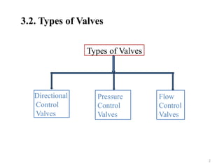
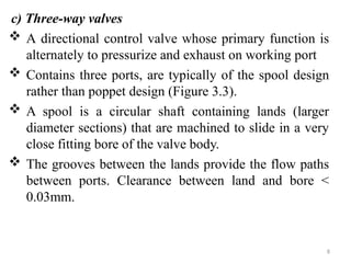
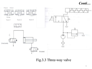
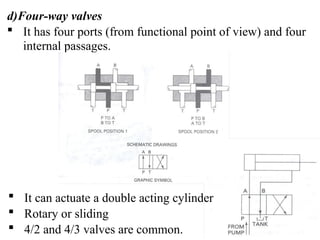


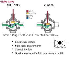
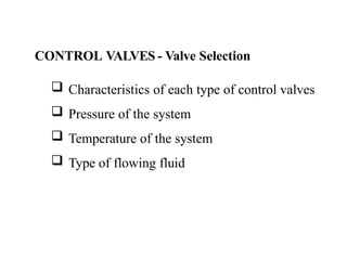
The document discusses various types of valves used in fluid control systems, focusing on directional control, pressure control, and flow control valves. It outlines the functions and characteristics of different valve types such as check valves, three-way valves, and pressure relief valves, along with their applications and methods of actuation. Additionally, it emphasizes the importance of proper valve selection based on system requirements like pressure, temperature, and fluid type.


