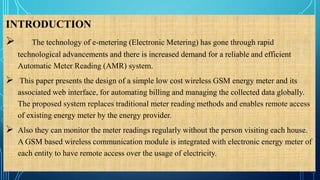
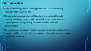
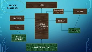
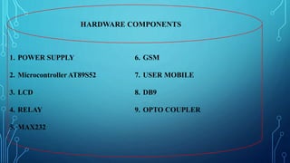
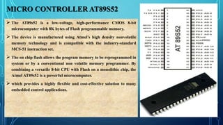
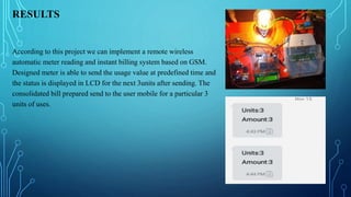
GSM BASED AUTOMATIC ENERGY METER READING AND
INSTANT BILLING SYSTEM
DEPARTMENT OF ELECTRONICS AND COMMUNICATION ENGINEERING
UNDER THE GUIDANCE OF
P. VISHNU PAVAN
ASST. PROF
BY
Khiti ranjan jena (14BH1A0466)
Komaragiri Sanjay (14BH1A0469)
Madhugula Bhanu (14BH1A0481)
Suman Mandal (14BH1A0487)
CONTENTS:-
INTRODUCTION
EXISTING SYSTEM
PROPOSED SYSTEM
BLOCK DIAGRAM
HARDWARE REQUIREMENTS
SOFTWARE REQUIREMENTS
ADVANTAGES
RESULT
CONCLUSION
FEATURE SCOPE
INTRODUCTION
 The technology of e-metering (Electronic Metering) has gone through rapid
technological advancements and there is increased demand for a reliable and efficient
Automatic Meter Reading (AMR) system.
 This paper presents the design of a simple low cost wireless GSM energy meter and its
associated web interface, for automating billing and managing the collected data globally.
The proposed system replaces traditional meter reading methods and enables remote access
of existing energy meter by the energy provider.
 Also they can monitor the meter readings regularly without the person visiting each house.
A GSM based wireless communication module is integrated with electronic energy meter of
each entity to have remote access over the usage of electricity.
EXISTING SYSTEM:-
Now a days energy meter reading premise and takes the reading
manually then issues the bill.
In manually human error possible and not provide reliable meter
reading. An energy meter is a device which is used to measure the
consumption of energy of any residence or other industrial
establishment.
In conventional metering system to measure electricity consumption the
energy provider company hire a person who visit each house and record
the reading manually.
PROPOSED SYSTEM:-
In the system to explore the new possibilities for the next
generation Automatic meter reading whose goal is to collect
the meter reading Automatically.
Automation ranges from connecting meter through an RS232
interface for transmitting the meter measurements, all the way
meter to the utility company via GSM network.
MICRO
CONTROLLER
AT89S52
LCD
METER
RELAY
LOAD
MAX 232
GSM
USER
MOBILE
POWER SUPPLY
BLOCK
DIAGRAM
Optocoupl
er
HARDWARE COMPONENTS
1. POWER SUPPLY
2. Microcontroller AT89S52
3. LCD
4. RELAY
5. MAX232
6. GSM
7. USER MOBILE
8. DB9
9. OPTO COUPLER
MICRO CONTROLLER AT89S52
 The AT89s52 is a low-voltage, high-performance CMOS 8-bit
microcomputer with 8K bytes of Flash programmable memory.
 The device is manufactured using Atmel’s high density nonvolatile
memory technology and is compatible with the industry-standard
MCS-51 instruction set.
 The on chip flash allows the program memory to be reprogrammed in
system or by a conventional non volatile memory programmer. By
combining a versatile 8-bit CPU with Flash on a monolithic chip, the
Atmel AT89s52 is a powerful microcomputer.
 which provides a highly flexible and cost-effective solution to many
embedded control applications.
POWER SUPPLY
 The power supplies are designed to convert high voltage AC mains electricity to a
suitable low voltage supply for electronic circuits and other devices.
 A power supply can by broken down into a series of blocks, each of which
performs a particular function.
 A DC power supply which maintains the output voltage constant irrespective of AC
mains fluctuations or load variations is known as “Regulated DC Power Supply”.
The 5V regulated power supply system as shown below
LIQUID CRYSTAL DISPLAY (LCD):
Liquid crystal displays (LCD s) have materials which
combine the properties of both liquids and crystals.
Most common LCDs connected to the microcontroller.
Most common LCDs connected to the microcontroller
is 16*2.
This means 16 characters per line by 2 lines
RELAY
 Relays are simple switches which are operated both electrically and mechanically. Relays consist of an
electromagnet and also a set of contacts.
 The switching mechanism is carried out with the help of the electromagnet.
 There are also other operating principles for its working. But they differ according to their applications. Most
of the devices have the application of relays.
 The power source is given to the electromagnet through a control switch and through contacts to the load.
When current starts flowing through the control coil, the electromagnet starts energizing and thus intensifies
the magnetic field.
METER
An electricity meter, electric meter, electrical meter,
or energy meter is a device that measures the amount
of electric energy consumed by a residence, a business, or an
electrically powered device.
Electric utilities use electric meters installed at customers'
premises to measure electric energy delivered to their
customers for billing purposes.
Electric meters are typically calibrated in billing units, the
most common one being the kilowatt hour
MAX232
The MAX232 is an integrated circuit that converts signals from
an RS-232 serial port to signals suitable for use in TTL
compatible digital logic circuits
The MAX232 is a dual driver/receiver and typically converts the
RX, TX, CTS and RTS signals.
When a MAX232 IC receives a TTL level to convert, it changes a
TTL level to convert, it changes a TTL Logic 0 to between +3 and
+15v, and changes TTL Logic 1 to between -3 to -15v, and vice
versa for converting from RS232 to TTL
DB9
The DB9 (originally DE-9) connector is an
analog 9-pin plug of the D-sub miniature
connector family (D-sub or Sub-D).
 DCD, DSR, RTS and CTS are active low pins.
 The method used by RS232 for communication
allows for a simple connection of three lines
namely TX, RX, and Ground.
• TXD: Carries data from DTE to the DCE.
• RXD: Carries data from DCE to the DTE
• SG: Signal ground
GSM
The term GSM usually means the GSM standard and
protocols in the frequency spectrum around 900MHZ/
850/1800/ 1900MHZ.
Which can be used not only to access the internet, but also for
oral communication and for SMS.
A GSM modem is a specialized type modem which accepts a
sim card and operates over a subscription to a mobile operator
like mobile phone.
OPTOCOUPLER
 In electronics, an opto-isolator, also called an
photo coupler, or optical isolator.
 It is a component that transfers electrical signals
between two isolator circuit by using light.
 It prevents high voltage from effecting the
system receiving the signals.
SOFTWARE REQUIREMENTS
KIEL IDE
Embedded C
Flash Magic
Proteous
KEIL VISION-3
It is possible to create the source files in a text editor such as Notepad,
run the Compiler on each C source file, specifying a list of controls, run
the Assembler on each Assembler source file, specifying another list of
controls, run either the Library Manager or Linker (again specifying a list
of controls) and finally running the Object-HEX Converter to convert the
Linker output file to an Intel Hex File.
Once that has been completed the Hex File can be downloaded to the
target hardware and debugged.
 Unless you have to use the tolls on the command line, the choice is clear.
FLASH MAGIC
Flash magic is a PC tool for performing flash based microcontroller from
NXP using a serial or Ethernet protocol while in the target hardware.
Flash magic is a window software from the embedded system academy that
allows easy access to all the ISP features provided by the devices.
Erasing, Programming and reading the flash memory.
Modifying the boot vector and status byte.
Reading and writing the security bits.
EMBEDDED C
Embedded C is a set of language extensions for the C programming
language by the C standards.
Embedded C programming requires non standard extensions to the C
language in the order to support exotic features such as fixed point,
arithmetic, multiple distance memory banks and basic input output
operation.
It includes number of features not available in normal C.
ADVANTAGES
 Collects meter readings electronically.
 Reduce the utilities to the customers and the cost of delivering utilities to the
utility providers.
 By this project the government gets much profit by receiving the tax and bill
on time, by this we can help government in the development of our State, &
Country.
 The abstract of rural classification provides opportunities for new and more
efficient metering technologies.
RESULTS
According to this project we can implement a remote wireless
automatic meter reading and instant billing system based on GSM.
Designed meter is able to send the usage value at predefined time and
the status is displayed in LCD for the next 3units after sending. The
consolidated bill prepared send to the user mobile for a particular 3
units of uses.
CONCLUSION
Using this project we can reduce the manual effort to take the
readings from the energy meter which is cost effective solution.
Reduces man power.
It is user friendly and we can enhance the this project, in which an
electricity department can send message to the consumer about the
billing information.
FUTURE SCOPE
The concept can further be extended by integrating a
RFID smart card where in each card is provided to
automatically recharge the amount and send the same
information via GSM module. To the respective
phone number stored
Ppt gsm based automatic energy meter

Ppt gsm based automatic energy meter

  • 1.
    GSM BASED AUTOMATICENERGY METER READING AND INSTANT BILLING SYSTEM DEPARTMENT OF ELECTRONICS AND COMMUNICATION ENGINEERING UNDER THE GUIDANCE OF P. VISHNU PAVAN ASST. PROF BY Khiti ranjan jena (14BH1A0466) Komaragiri Sanjay (14BH1A0469) Madhugula Bhanu (14BH1A0481) Suman Mandal (14BH1A0487)
  • 2.
    CONTENTS:- INTRODUCTION EXISTING SYSTEM PROPOSED SYSTEM BLOCKDIAGRAM HARDWARE REQUIREMENTS SOFTWARE REQUIREMENTS ADVANTAGES RESULT CONCLUSION FEATURE SCOPE
  • 3.
    INTRODUCTION  The technologyof e-metering (Electronic Metering) has gone through rapid technological advancements and there is increased demand for a reliable and efficient Automatic Meter Reading (AMR) system.  This paper presents the design of a simple low cost wireless GSM energy meter and its associated web interface, for automating billing and managing the collected data globally. The proposed system replaces traditional meter reading methods and enables remote access of existing energy meter by the energy provider.  Also they can monitor the meter readings regularly without the person visiting each house. A GSM based wireless communication module is integrated with electronic energy meter of each entity to have remote access over the usage of electricity.
  • 4.
    EXISTING SYSTEM:- Now adays energy meter reading premise and takes the reading manually then issues the bill. In manually human error possible and not provide reliable meter reading. An energy meter is a device which is used to measure the consumption of energy of any residence or other industrial establishment. In conventional metering system to measure electricity consumption the energy provider company hire a person who visit each house and record the reading manually.
  • 5.
    PROPOSED SYSTEM:- In thesystem to explore the new possibilities for the next generation Automatic meter reading whose goal is to collect the meter reading Automatically. Automation ranges from connecting meter through an RS232 interface for transmitting the meter measurements, all the way meter to the utility company via GSM network.
  • 6.
  • 7.
    HARDWARE COMPONENTS 1. POWERSUPPLY 2. Microcontroller AT89S52 3. LCD 4. RELAY 5. MAX232 6. GSM 7. USER MOBILE 8. DB9 9. OPTO COUPLER
  • 8.
    MICRO CONTROLLER AT89S52 The AT89s52 is a low-voltage, high-performance CMOS 8-bit microcomputer with 8K bytes of Flash programmable memory.  The device is manufactured using Atmel’s high density nonvolatile memory technology and is compatible with the industry-standard MCS-51 instruction set.  The on chip flash allows the program memory to be reprogrammed in system or by a conventional non volatile memory programmer. By combining a versatile 8-bit CPU with Flash on a monolithic chip, the Atmel AT89s52 is a powerful microcomputer.  which provides a highly flexible and cost-effective solution to many embedded control applications.
  • 9.
    POWER SUPPLY  Thepower supplies are designed to convert high voltage AC mains electricity to a suitable low voltage supply for electronic circuits and other devices.  A power supply can by broken down into a series of blocks, each of which performs a particular function.  A DC power supply which maintains the output voltage constant irrespective of AC mains fluctuations or load variations is known as “Regulated DC Power Supply”. The 5V regulated power supply system as shown below
  • 10.
    LIQUID CRYSTAL DISPLAY(LCD): Liquid crystal displays (LCD s) have materials which combine the properties of both liquids and crystals. Most common LCDs connected to the microcontroller. Most common LCDs connected to the microcontroller is 16*2. This means 16 characters per line by 2 lines
  • 11.
    RELAY  Relays aresimple switches which are operated both electrically and mechanically. Relays consist of an electromagnet and also a set of contacts.  The switching mechanism is carried out with the help of the electromagnet.  There are also other operating principles for its working. But they differ according to their applications. Most of the devices have the application of relays.  The power source is given to the electromagnet through a control switch and through contacts to the load. When current starts flowing through the control coil, the electromagnet starts energizing and thus intensifies the magnetic field.
  • 12.
    METER An electricity meter,electric meter, electrical meter, or energy meter is a device that measures the amount of electric energy consumed by a residence, a business, or an electrically powered device. Electric utilities use electric meters installed at customers' premises to measure electric energy delivered to their customers for billing purposes. Electric meters are typically calibrated in billing units, the most common one being the kilowatt hour
  • 13.
    MAX232 The MAX232 isan integrated circuit that converts signals from an RS-232 serial port to signals suitable for use in TTL compatible digital logic circuits The MAX232 is a dual driver/receiver and typically converts the RX, TX, CTS and RTS signals. When a MAX232 IC receives a TTL level to convert, it changes a TTL level to convert, it changes a TTL Logic 0 to between +3 and +15v, and changes TTL Logic 1 to between -3 to -15v, and vice versa for converting from RS232 to TTL
  • 14.
    DB9 The DB9 (originallyDE-9) connector is an analog 9-pin plug of the D-sub miniature connector family (D-sub or Sub-D).  DCD, DSR, RTS and CTS are active low pins.  The method used by RS232 for communication allows for a simple connection of three lines namely TX, RX, and Ground. • TXD: Carries data from DTE to the DCE. • RXD: Carries data from DCE to the DTE • SG: Signal ground
  • 15.
    GSM The term GSMusually means the GSM standard and protocols in the frequency spectrum around 900MHZ/ 850/1800/ 1900MHZ. Which can be used not only to access the internet, but also for oral communication and for SMS. A GSM modem is a specialized type modem which accepts a sim card and operates over a subscription to a mobile operator like mobile phone.
  • 16.
    OPTOCOUPLER  In electronics,an opto-isolator, also called an photo coupler, or optical isolator.  It is a component that transfers electrical signals between two isolator circuit by using light.  It prevents high voltage from effecting the system receiving the signals.
  • 17.
  • 18.
    KEIL VISION-3 It ispossible to create the source files in a text editor such as Notepad, run the Compiler on each C source file, specifying a list of controls, run the Assembler on each Assembler source file, specifying another list of controls, run either the Library Manager or Linker (again specifying a list of controls) and finally running the Object-HEX Converter to convert the Linker output file to an Intel Hex File. Once that has been completed the Hex File can be downloaded to the target hardware and debugged.  Unless you have to use the tolls on the command line, the choice is clear.
  • 19.
    FLASH MAGIC Flash magicis a PC tool for performing flash based microcontroller from NXP using a serial or Ethernet protocol while in the target hardware. Flash magic is a window software from the embedded system academy that allows easy access to all the ISP features provided by the devices. Erasing, Programming and reading the flash memory. Modifying the boot vector and status byte. Reading and writing the security bits.
  • 20.
    EMBEDDED C Embedded Cis a set of language extensions for the C programming language by the C standards. Embedded C programming requires non standard extensions to the C language in the order to support exotic features such as fixed point, arithmetic, multiple distance memory banks and basic input output operation. It includes number of features not available in normal C.
  • 21.
    ADVANTAGES  Collects meterreadings electronically.  Reduce the utilities to the customers and the cost of delivering utilities to the utility providers.  By this project the government gets much profit by receiving the tax and bill on time, by this we can help government in the development of our State, & Country.  The abstract of rural classification provides opportunities for new and more efficient metering technologies.
  • 22.
    RESULTS According to thisproject we can implement a remote wireless automatic meter reading and instant billing system based on GSM. Designed meter is able to send the usage value at predefined time and the status is displayed in LCD for the next 3units after sending. The consolidated bill prepared send to the user mobile for a particular 3 units of uses.
  • 23.
    CONCLUSION Using this projectwe can reduce the manual effort to take the readings from the energy meter which is cost effective solution. Reduces man power. It is user friendly and we can enhance the this project, in which an electricity department can send message to the consumer about the billing information.
  • 24.
    FUTURE SCOPE The conceptcan further be extended by integrating a RFID smart card where in each card is provided to automatically recharge the amount and send the same information via GSM module. To the respective phone number stored