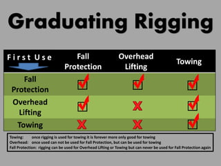
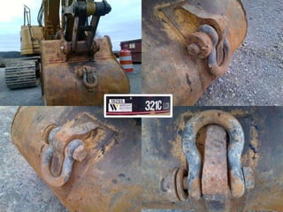
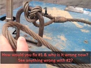
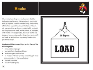
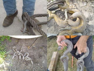
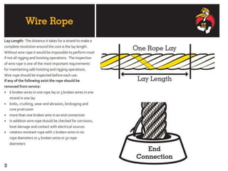
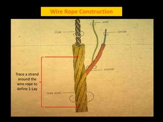
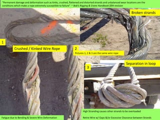
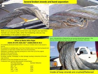
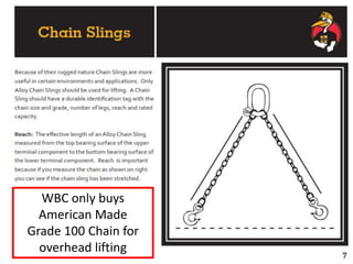
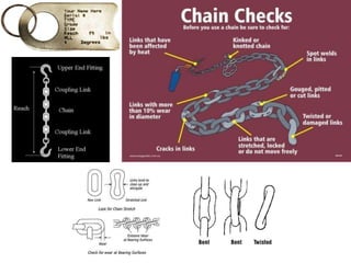
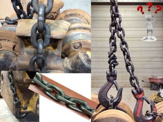
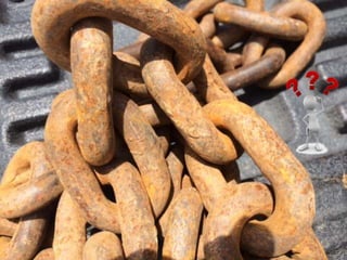
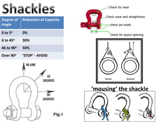
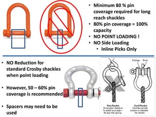
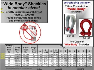
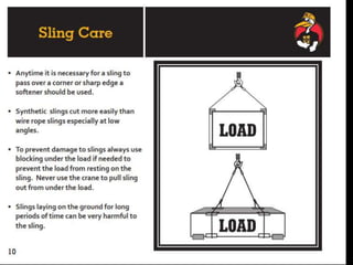
The document discusses various issues with rigging, including that rigging is complicated and breaks for no reason. It also mentions that rigging is worn out and too expensive to replace with hardware store items. The document then provides information on proper rigging use and inspection, including graduation rules for different types of rigging use, manufacturer and wear identification, and inspection criteria. It also covers wire rope construction, types of synthetic round slings, and various rigging configurations and their capacities.
Booking open Available Pune Call Girls Koregaon Park 6297143586 Call Hot Ind...
Rigging 101: Essential Guide to Rigging Fundamentals, Inspection, Safety and Applications
1. • I don’t understand Rigging
• Rigging is Complicated
• Rigging Breaks for No Reason
• They wouldn’t get me what I need
• I can ‘t find our Rigging
• We have to ‘get it done’
• Our Rigging is worn out
• Rigging is too expensive
• We can replace Rigging at the hardware store
WBC Rigging 101
14. • Manufacturers'
identification
• Never weld on hooks
• Working safety latch
Hooks are
designed to
apply the
load at the
bottom of the
saddle.
Hook Wear – Allowable %’s
•Eye = 5%
•Neck = 5%
•Throat Opening = 5%
•Everything Else =10%
Additionally Crosby have quick check marks
For measuring – they are in 1” to .5” increments
21. Broken strands
Crushed / Kinked Wire Rope
Fatigue due to Bending & Severe Wire Deformation
“Permanent damage and deformation such as kinks, crushed, flattened and distorted strands and unbalanced wear locations are the
conditions which make a rope extremely susceptible to failure” ~ Bob’s Rigging & Crane Handbook fifth revision
1
2
Pictures 1, 2 & 3 are the same wire rope
High Stranding causes other strands to be overloaded
Retire Wire w/ Gaps &/or Excessive Clearance between Strands
Separation in loop
3
22. Several broken strands and band separation
When to Retire Wire Rope
OSHA 29 CFR 1926.550 * ASME/ANSI B 30.5
1-6 randomly distributed broken wires in one lay or 3 broken wires in one strand in
one lay
2-In pendants or standing ropes, more than 2 broken wires in one rope lay beyond end
connections or more than 1 broken wire at an end connection
3-Abrasion, scrubbing or peening causing loss or more than 1/3 of the original
diameter of the outside wires
4-Evidence of severe corrosion
5-Linking, crushing, “birdcaging” or other damage resulting in distortion of the wire
rope structure
6-Evidence of any heat damage from any cause
7-reduction from nominal rope diameter as listed below :
Wire Rope Diameter Diameter Reduction
up through 5/16”1/64”
3/8” – ½” 1/32”
9/16” - 3’4” 3/64”
7/8” – 1 1/8” 1/16”
1 1/4” – 1 ½” 3/32”
Make sure you are using the correct wire rope sling for your operation:
Example use a shorter cable, rather than basketting / also you may
need thimbles in the eyelets to reduce wear
Inside of loop strands are crushed/flattened
Worn / Abraded Wire is flattened by use causing reduced wire diameter –This
Must be retired when the wear exceeds 1/3 of the diameter of the wire
23.
24. 3/8” Wire Rope - & Crosby Cable Clamp – Critical Test (3-3-3 Rule)
Components & Capacities:
• 3/8” Galv. Wire Rope Breaking Strength= 14,400#
• With 5x safety factor = working load of 2,880#
• 3/8” Crosby Clamp Efficient rate of 80% = 2,304#
• (w/5x safety factor)
• 2x Safe working load for wire rope = 5,760#
• 2x 80% cable clamp = 4,608#
Tested:
• 2ea. wire rope slings made with 6ea. cable clamps creating 2 eyes.
• Cable clamps were spread 3” apart and used 3 clamps for each eye
• Differences:
• Sling A - made with clamps torque to 45lbs (generally 5 threads revealed)
• Sling B - torqued to only reveal 3 full rotation of threads
Results:
• Sling B - following the “3-3-3” rule tested to failure reaching 13,330# with no slippage of any clamps, also 2 strands
were not sheared. Almost 6x the efficient rate certified by Crosby.
• Sling A - following the 45lb torque on the cable clamps tested to failure at just over 12,000# and is suspect to slight
clamp slippage. This sling also created well defined kinks in the wire rope, which leads me to question potential
crushed wires thus adding to the failure at a reduced capacity as compared to the 1st test.
33. Part No. Color Vertical
Capacity
Choker
Capacity
Basket
Capacity
Min.
Length
Body
Width
Min.
D to d
Min.
Connection
Width
ARS – 30 Purple 2,650 2,120 5,300 3’ 1 1/8” 19/32” 1 3/16”
ARS – 60 Green 5,300 4,240 10,600 3’ 1 1/12” ¾” 1 ½”
ARS – 90 Yellow 8,400 6,720 16,800 3’ 1 7/8” 29/32” 1 5/16”
ARS – 120 Tan 10,600 8,500 21,200 3’ 2 1/8” 1 1/16” 2 3/32”
ARS – 150 Red 13,200 10,560 26,400 3’ 2 ¼” 1 3/16” 2 13/32”
ARS – 180 White 16,800 13,440 33,600 6’ 2 ½” 1 11/32” 2 17/32”
ARS – 240 Blue 21,200 17,000 42,400 6’ 3” 1 ½” 3 5/32”
ARS – 300 Orange 25,00 20,000 50,000 6’ 3 7/8” 1 ½” 3 15/32”
ARS – 360 Gray 31,700 25,300 63,400 6’ 3 ¾” 1 13/16” 3 ¾”
ARS – 500 Orange 40,000 32,000 80,000 7’ 4 ¼” 1 15/16” 4 3/16”
ARS – 600 Brown 52,900 42,300 105,800 7’ 4 5/8” 2 ¼” 4 13/16”
ARS – 800 Olive 66,100 52,880 132,200 7’ 5 ¼” 2 17/32” 5 13/32”
ARS - 1000 Black 90,000 72,000 180,000 7’ 5 7/8” 3” 6 5/32”
Endless Polyester Round Slings Capacities & minimum diameters
34. Synthetic Round Slings have a double layer sheath. To inspect this type of rigging first look for
cuts in the sheaths, the outer layer may be cut however, if the underlayer is cut the sling MUST
be retired.
If the sling passes this inspection, then feel the entire length of the sling with your fingers, you
are feeling for either hard spots or knots, if you find either the sling MUST be retired.
Also these slings MUST have a load rating tag on them, if they don’t Dispose of them. (this is
the same requirement as nylon slings)
OUTER SHEATH
SYNTHETIC CORE
INSIDE SHEATH
35. Severely torn straps / “red is dead” / No knots / Must have load rating on attached tag
36. Sling Eye
The object in the eye creates an
angle for the sling
(see red arrows, to right)
Diameter of object in the slings eye should not exceed:
Wire Rope = 1/2 diameter of the eye
Synthetic Sling = 1/3 diameter of the eye
37.
38.
39. Degree of
Angle
Reduction of Capacity
0 to 5o 0%
6 to 45o 30%
46 to 90o 50%
Over 90o ‘STOP’ - AVOID
‘mousing’ the shackle
40. • Minimum 80 % pin
coverage required for long
reach shackles
• 80% pin coverage = 100%
capacity
• NO POINT LOADING !
• NO Side Loading
• Inline Picks Only
• NO Reduction for
standard Crosby shackles
when point loading
• However, 50 – 60% pin
coverage is recommended
• Spacers may need to be
used
41.
42.
43.
44. Vertical Pull = 3,100
Choked = 2,480
WHY?
3,100 x.80 = 2,480
(est)
Choker Hitches are generally 75%
(conservative) of Vertical Pull
When calculating capacity (in
perfect condition @ 135o)
However, the chart here uses .80
45. True Basket = 2x the vertical load limit
If both eyes are connected at the same point use Reduction Factor:
• 90o = 2 x vertical rating
• 60o = 1.7 x vertical rating
• 45o = 1.4 x vertical rating
• 30o = 1 x vertical Not TRUE Vertical Basket
Hitch comparison of capacities
A = Vertical / B = Choker / C = Vertical Basket
46.
47. When using Multiple Basket or Choker Hitches
The load should be rigged to prevent the Sling
from Slipping or Sliding along the Load.
Double Leg Basket is formed by connecting the
two basket hitches to the load. The double leg
basket may have 2x the capacity of a bridle at
the same sling angle. A double leg basket must
not be used at a sling angle less than 60o. At
smaller horizontal sling angles the slings will
slide inward. The single wrap basket hitches do
not provide a full 360o contact with the load.
The double wrap basket hitch provides the
improved grip on the load. Do not use a sling
angle less than 45o.
Make sure the double wrap basket doesn’t
overlap on the bottom of the load. Adjust both
sides of each basket to equalize the load in
each leg.
52. 4,000
lbs.
4,000
lbs.
8,000 lbs. 8,000 lbs. 8,000 lbs. 8,000 lbs.
8,000 lbs. 8,000 lbs.
CAPACITY = 5,700 (ea. leg) Total 9,900 lbs. (combined) Total 8,100 lbs. (combined) TOTAL 5,700 lbs. (combined)
Load on rigging = 8,000 lbs. Total 9,232 lbs. Total 11,312 lbs. TOTAL 16,000 lbs.
• Suppose you have a ‘vertical’ working load rating of 8,000 lbs
• How can rigging have more weight than the weight of the object?
• Envision rigging angles trying to collapse the load your picking
53. L=12’
(144”)
H=10’5”
(125”)
(10,500 lbs.)
Calculating Weight Per Leg:
H=10’5” (125”)
L=12’ (144”)
144” / 125” = 1.152
Load Angle Factor= 1.152
Multiply Load Angle by weight of object
1.152 x 10,500 = lbs (total load on slings)
12,096 lbs divided by # of sling legs
12,096 / 2 = 6,048 lbs. (total load on each sling)
Your rigging has:
3/8” vertical capacity = 8,800
1st Calculate Sling Angle:
H-125” / L-144” = .868 (= 60o from chart)
2nd Calculate Total Reduction from Angle
.868 x 8,800 = 7,638 (ea. leg up to 2)
L/H (Sling Tension)
• This example you have tagged
rigging and are determining if it is
correct for the weight you are
going to pick
• Here you are calculating the
weight (tension) at the
specific angle & comparing
information against your
rigging chart /rated capacity
H/L ( Reduction Factor)
• This example you are calculating
the reduction factor for the
rigging at the specific angle
• Here you have the vertical
capacity of your rigging &
are determining the
reduction at specific angle
55. 50 tons
25 feet
5 ton
100 feet
Capacity Lift: Any lift which is close to the maximum
capacity of a crane at any given radius.
Big Load at Little Radius Little Load at Big Radius
56. Effect of Not Having a Level Crane
25 feet
25 feet
New Radius ?
Level Set-Up Out-of-Level Set-Up
57. Effect of Exceeding a Cranes Safe Working
Radius
Structural Failure Tipping Failure
58.
59. • RT Cranes must have all tires off the ground while
making picks, otherwise the ‘on-rubber’ chart must
be used.
(In this picture the tire is not only on the ground but
bearing weight)
• Outrigger pads must be properly protected against
poor bearing pressure conditions and soils.
• Blocking of the outrigger pad must not be span-
blocked and the surface area of the pad depends
on the weight of the crane, weight of the pick and
all rigging, soil GBC (gross bearing capacity) in order
to make the appropriate calculations.
Outrigger Pads / Bearing Pressure
60. Set-Back Distance for Sloping Ground Set-Back Distance for Temporary Wall or Shoring
Set-Back Distance for 1-1/2 to 1 Slopes
When mobile crane is setup adjacent to a
slope, excavation or temporary structure
the minimum set back distance shall be
as shown, here, unless otherwise
determined in an analysis performed by a
qualified engineer.
This method for estimating setback distance from slopes, excavations
and retaining walls can be implemented by a qualified person, but is
not intended to be applicable for every situation or substituted for
analysis when conditions warrant.
61. • Do not set the outrigger on uneven soil. If necessary, reposition the unit or level the
soil.
• Do not set the outrigger on a hill. The force of the machine weight must be transmitted
straight down, otherwise the outrigger load would be partially down and partially
sideways, putting undue strain on the outrigger leg.
• Do not bridge a hole with outrigger cribbing. If there is no soil contact over the hole,
the pressure on the ends of the pad is much greater. The soil could give way or the
cribbing could break.
• If you determine that you need five pieces of cribbing to support the load but the foot
only touches three of them, the outrigger will sink into the soil. To avoid this problem,
lay dunnage the opposite direction on top of the first layer. The top layer of dunnage
must contact all pieces that are supporting it.
• When jacking, put the full weight of the truck on each outrigger, one at a time, and if
the pad starts to sink, retract the foot and supply more cribbing. Continue this process
until the outrigger appears stable and the pad shows no sign of sinking. Only then are
you ready to unfold the boom.
• If you are unable to get the outriggers to stabilize, do not unfold the boom. Relocate
the pump to a location that will support the weight of the outriggers.
Cribbing: more or less?
• More is better
• The stronger the material, the better
• Pay close attention to the type of soil where you're setting up the unit.
62. Double Layer Hardwood 4x4 pads will be
used at a minimum, if pads settle more
than 1” or conditions are otherwise
insufficient cranes pads should be
substituted