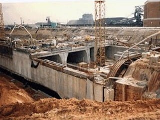
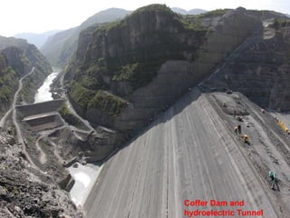
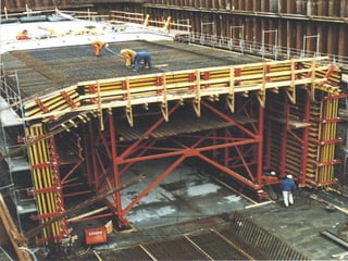
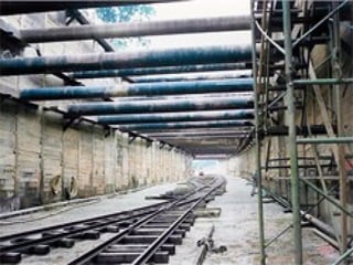
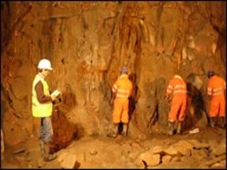
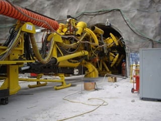
SlideShare a Scribd company logo
Definition 
Tunnels are artificial underground 
passages opened at both ends 
constructed for different purposes. 
Required for highways, railways, 
sewerage, water supply, public utilities 
and canals. 
Necessitated when open excavation of 
strata becomes uneconomical, not only 
construction cost but for maintenance as 
well. 
Continued 
Tunneling
History 
The oldest tunnel was constructed 4000 
years ago in ancient Babylon to underpass 
the bed of river Euphrates and to establish 
an underground connection between the 
royal palace and Temple of Jove. 
The length of the tunnel was 1 km and it was 
built with the considerable cross-section 
dimensions of 3.6 m by 4.5 m. 
In the second half of the 20th century, with 
the progress in development of both 
explosives and equipment, underground 
construction became feasible. 
Continued
Geological Considerations or ground 
properties before constructing any tunnel 
project: 
The engineering properties of a rock 
generally depend not only on the matrix 
(structure formed by the minerals) but 
also imperfections in the structure such 
as voids (pore space ),cracks ,inclusions, 
grain boundaries and weak particles. 
Pore spaces are largely made up of 
continuous irregular capillary cracks 
separating the mineral grains.
Physical discontinuities are present in all 
rock masses as a result of geological 
activities. 
Introduction of defects into the rock mass 
due to human activities that alter the 
properties of the rock material. 
The mechanical breaks in the rock have 
zero or low tensile strengths, increase 
rock deformability and provide pathways 
for water to flow.
Crown: The uppermost 
part of the tunnel 
Transportation tunnel cross-sections 
Wall 
Crown 
Core (strozze) Springline 
Invert 
•Springline : The 
line at which the 
tunnel wall breaks 
from sloping 
outward to sloping 
inward toward the 
crown 
Top heading 
Bench 
Bottom 
Circular Horseshoe Vertical walls arch roof 
Invert : The bottom Heading : The excavated face of the tunnel 
(floor) of the tunnel 
Drift : A 
horizontal 
excavation 
Station : The distance measured from the portal (chainage) 
Wall : The side of the tunnel Portal : The tunnel entrance
The choice of tunnelling method 
may be dictated by: 
geological and hydrological 
conditions 
Weak rock under high stresses 
leads to squeezing ground 
conditions. 
Brittle strong rock high stress 
conditions may lead to rockbursting. 
 cross-section and length of 
continuous tunnel 
local experience and time/cost 
considerations (what is the value 
of time in the project) 
limits of surface disturbance, 
and many others factors 
Choice of method 
depends upon 
nature of strata 
and geometry of 
tunnel section 
Continued
Methods divided into three categories 
Firm ground- reasonable time available for 
installing conventional support. 
Soft ground- Conventional support can not be 
installed. 
Running ground- Special treatment required 
before starting excavation 
Continued 
Classification ooff TTuunnnneelllliinngg 
MMeetthhooddss bbaasseedd oonn ttyyppee ooff ssttrraattaa::
TTuunnnneelllliinngg MMeetthhooddss 
Rough classification of methods 
 Excavation: An excavation process without 
removing the overlying rock or soil 
• Steps: excavating-remove muck-supporting-lining- 
ventilation-draining 
• Drill & Blast, hammer, roadheader, .... 
Cut and cover: trenching to excavate and construct a 
tunnel, and then backfilling earth over it. 
Immersed tunnel: lowering prefabricated tunnel 
elements into a dredged channel and joining them 
up under water 
• Concrete 
• Steel 
Continued
Bottom-up method: The main site is excavated, 
with ground support as necessary, and the tunnel 
is constructed within. The tunnel may be of in situ 
concrete, precast concrete, precast arches, or 
corrugated steel arches. The trench is then 
carefully back-filled above the tunnel roof and the 
surface is restored.
Coffer Dam and 
hydroelectric Tunnel
Top-down method: Here side support walls and 
cap beams are constructed from ground level 
typically with slurry walls, or secant piling. Then a 
shallow excavation allows making the tunnel roof 
of precast beams or in situ concrete. The surface is 
then restored except for access openings. This 
allows early reinstatement of roadways, services 
and other surface features. Excavation then takes 
place under the permanent tunnel roof, and the 
base slab is constructed.
Tunnelling in Firm ground 
Traditional methods. Involving drilling and blasting 
Full Face Method. In firm soils where full 
face excavation can hold it self for 
sufficient time to allow mucking and 
supporting operations. 
In the full-face method, workers excavate 
the entire diameter of the tunnel at the 
same time. 
This is most suitable for tunnels passing 
through strong ground or for building 
smaller tunnels. 
Continued
Top Heading and benching. When full face 
excavation is not possible. Heading should be 
sufficient distance ahead of benching. 
In this technique, workers dig a smaller tunnel 
known as a heading. Once the top heading has 
advanced some distance into the rock, workers begin 
excavating immediately below the floor of the top 
heading; this is a bench. 
 One advantage of the top-heading-and-bench 
method is that engineers can use the heading tunnel 
to gauge the stability of the rock before moving 
forward with the project.
Excavation by tunnelling Methods 
 Drift Method. In case of large or pilot tunnel , Drift is made 
and then expanded. There can be more than one drifts. 
 Different ‘drift methods’ depending on location of drift can be 
used.
Tunnelling in Soft Strata 
Tunnels constructed in soft materials 
require temporary support immediately or 
shortly after excavation. Way to provide 
support are: 
Suitably spaced bents of wood 
Suitably spaced bents of steel for lagging 
(covering) 
Liner plates 
Fore poling placed to retain material 
between adjacent bents 
Temporary supports must be designed for 
higher working stress compared to those in 
permanent designs.
Tunnelling in Soft Ground 
Instantaneous support is required 
No drilling and blasting. 
Forepoling is done. 
 Boards are driven ahead of the last ‘rib’, around 
periphery 
 Forepoles act as cantilevers beyond breasting 
 Soil is excavated after removing the breast board and 
new rib is erected 
Continued
Because stand-up time is generally short when 
tunneling through soft ground, cave-ins are a 
constant threat. To prevent this from happening, 
engineers use a special piece of equipment called a 
shield. 
A shield is an iron or steel cylinder literally pushed 
into the soft soil. It carves a perfectly round hole and 
supports the surrounding earth while workers remove 
debris and install a permanent lining made of cast 
iron or precast concrete. 
When the workers complete a section, jacks push the 
shield forward and they repeat the process.
Tunnelling in Running Ground 
Many methods 
Principle is, Linear plates are pushed in starting 
from crown 
Cavity is excavated 
Additional linear plates are pushed one by one and 
bolted 
Arch section gradually widened down to springing 
line. 
Continued
Tunnelling in Rocks 
Tunnels are driven in rocks by drilling holes in the 
rock face, loading the holes with explosives, blasting 
and removing the broken rock 
Each sequence full cross section of the tunnel may be 
excavated, or one or more drifts may be there. 
Drilling pattern for holes of explosives may differ 
depending upon rock type, cross section, experience 
expertise and type of explosive suggested. 
Methods are similar in principle like 
 Full Face Method 
 Top Heading and benching 
 Drift Method 
Continued
Tunneling through hard rock almost always involves 
blasting. Workers use a scaffold, called a jumbo, to place 
explosives quickly and safely. 
The jumbo moves to the face of the tunnel, and drills 
mounted to the jumbo make several holes in the rock. The 
depth of the holes can vary depending on the type of rock, 
but a typical hole is about 10 feet deep and only a few 
inches in diameter. 
Next, workers pack explosives into the holes, evacuate the 
tunnel and detonate the charges. After vacuuming out the 
noxious fumes created during the explosion, workers can 
enter and begin carrying out the debris, known as muck, 
using carts. 
 Then they repeat the process, which advances the tunnel 
slowly through the rock.
Fire-setting is an alternative to blasting. In this 
technique, the tunnel wall is heated with fire, and then 
cooled with water. The rapid expansion and contraction 
caused by the sudden temperature change causes large 
chunks of rock to break off. The Cloaca Maxima, one of 
Rome's oldest sewer tunnels, was built using this 
technique. 
The stand-up time for solid, very hard rock may measure 
in centuries. In this environment, extra support for the 
tunnel roof and walls may not be required. However, most 
tunnels pass through rock that contains breaks or pockets 
of fractured rock, so engineers must add additional 
support in the form of bolts, sprayed concrete or rings of 
steel beams. In most cases, they add a permanent concrete 
lining
Sequence of operation in Rocky 
Strata (Drill and Blast) 
Marking tunnel profile. 
Setting up and drilling 
Loading explosive and blasting 
Removing the foul gases 
Checking 
Scaling 
Mucking 
Rock bolting and lining 
Continued
Modern Tunnel Construction Methods: 
 Drill and blast 
 Mechanical drilling/cutting 
 Cut-and-cover 
 Immersed tunnels 
 Tunnel boring machines (TBMs) 
 New Austrian Tunnelling Method 
(NATM) 
Continued
Road headers
Types of support 
Steel arches 
Steel ribs are used for reinforcement of weaker tunnel 
sections, and give rigid to semi-rigid support. The ribs are 
made from I-beam or H-beam structural steel bent to 
conform to the requirements of a particular tunnel cross-section. 
Timber may be used for packing between the beams and 
the rock. However, providing continuous bedding against 
the rock may considerably increase the load-bearing 
capacity of the arches. 
Continued
Rock bolts 
Steel bolts are frequently set in holes drilled into the rock 
to assist in supporting the entire roof or individual rock 
slabs that tend to fall into a tunnel. Rock bolts maintain 
the stability of an opening by suspending the dead weight 
of a slab from the rock above 
Continued
Shotcrete 
Pneumatically applied mortar and concrete are 
increasingly being used for the support of underground 
excavations. 
A combination of rock bolts and shotcrete has proved an 
excellent temporary support for all qualities of rock. 
Shotcrete is best known in tunnelling as an integral 
component of the NATM (New Austrian Tunnelling 
Method). 
Quick-setting concrete is sprayed onto the bare rock 
surface immediately after excavation, and rapidly hardens 
to form a preliminary support until the final lining of 
conventional poured concrete can be installed. 
Continued
Wire mesh 
Wire mesh is used to support small pieces of loose rock 
or as reinforcement for shotcrete. 
Two types of wire mesh 
chain link mesh commonly used for fencing and it 
consists of a woven fabric of wire, tends to be flexible 
and strong 
weld mesh. commonly used for reinforcing shotcrete 
and it consists of a square grid of steel wires, welded 
at their intersection points.
Ventilation during construction 
Why required? 
To furnish fresh air for the workers 
To remove the dust caused by drilling, blasting, 
mucking, diesel engines, and other operations 
To remove obnoxious gases and fumes of explosives 
How done? 
Mechanical ventilation is usually supplied by electric 
fans, as for example axial flow pressure fans. 
 If air is blown into a tunnel, it may be forced through a 
lightweight pipe or fabric duct. 
 If air is exhausted, it is necessary to use a rigid duct that will 
not collapse. 
The exhaust method has the advantage of more 
quickly removing objectionable air from spaces 
occupied by the workers. 
Continued
Ventilation of tunnels 
Mechanical ventilation systems provide the temperature, 
humidity and air velocity conditions necessary to give 
tunnel users a reasonable degree of comfort during normal 
operation. 
 When a fire occurs in a tunnel, the system must also 
provide a safe evacuation route for tunnel users and 
access for fire fighting services. 
The choice and design of a ventilation system depends on 
these main factors: 
tunnel length and volume 
admissible air pollution around tunnel portals 
fire safety considerations. 
Key pollutants include carbon dioxide, nitrogen oxides, 
nitrogen dioxide, hydrocarbons PM10 and lead. 
Better understanding of ventilation techniques 
Awareness of new safety and environmental legislation.
Geological Survey For Tunneling 
 A geological survey is the systematic investigation 
of the subsurface and surface of a given piece of 
ground for the purpose of creating a geological 
map ,model and feasibility studies. 
 A geological survey employs techniques from the 
traditional walk-over survey, studying outcrops 
and landforms, to intrusive methods, such as hand 
auguring and machine driven boreholes, use of 
geophysical techniques and remote sensing 
methods, such as aerial photography and satellite 
imagery etc.
Types Of Geological Survey 
 Mainly geological surveys are classified into 
two types: 
Surface Geological Survey 
Subsurface Geological Survey 
 Surface Geological Survey: includes on land 
geology and geological 
structures,landforms,hydrology,outcrop 
pattern ,engineering properties etc 
 Subsurface Geological Survey: : includes on 
underground geology and geological 
structures,Geo-hydrogeology,subsurface rock 
or soil pattern etc
Surface Geological Survey 
Geological profile is prepared along line of tunnel. 
Geological observations are done along this profile 
like engineering properties of rock/soil, geological 
structures like fold,faults,joints,spring,stream,river 
alignment and any seepage etc 
Trial boring plan is prepared along the tunnel line.
Subsurface Geological Survey 
Trial boring is done along the tunnel line. 
Different rock and soil samples are collected 
from subsurface and their physical and 
chemical properties are observed. 
Some samples are sent to laboratory for 
determination of engineering properties like 
shearing,strenght,permeability,porosity,compr 
essive strenght,and other test are performed. 
GWT(Ground Water Table) is noted and water 
bearing strata is marked in geological profile.
Different geophysical surveys like refraction, 
resistivity, GPR(Ground Penetrating Radar) and 
bor hole logging etc are also done. 
In situ testing like Packer-testing, hydro 
fracturing, load-testing etc are performed. 
A geological/feasibility report comprising all 
information ,photographs, profile and others 
necessary data are presented for final tunnel 
design and construction.
Subsurface 
Profiling/3 D 
modelling

More Related Content

What's hot

Tunnelling methods
Tunnelling methodsTunnelling methods
Tunnelling methods
jagadish chintu
 
Study of tunnel engineering
Study of tunnel engineeringStudy of tunnel engineering
Study of tunnel engineering
Adil Shaikh
 
Geotechnical investigations for tunnelling
Geotechnical  investigations for tunnellingGeotechnical  investigations for tunnelling
Geotechnical investigations for tunnelling
Prof. A.Balasubramanian
 
Geology of Dams & Reservoirs
Geology of Dams & ReservoirsGeology of Dams & Reservoirs
Geology of Dams & Reservoirs
Hymavathi Jampani
 
Subsurface exploration
Subsurface exploration  Subsurface exploration
Subsurface exploration
Shruthi Hiremath
 
Tunnelling methods
Tunnelling methodsTunnelling methods
Tunnelling methods
Durgesh Kumar Yadav
 
Tunneling & Drilling Equipments
Tunneling & Drilling EquipmentsTunneling & Drilling Equipments
Tunneling & Drilling Equipments
Rajarshi Patty
 
Tunnel making methods and tunnel boring machine
Tunnel making methods and tunnel boring machine Tunnel making methods and tunnel boring machine
Tunnel making methods and tunnel boring machine mohammadsalikali
 
7. TUNNEL ENGINEERING
7. TUNNEL ENGINEERING7. TUNNEL ENGINEERING
7. TUNNEL ENGINEERING
VATSAL PATEL
 
types of dam
types of damtypes of dam
types of dam
Akshay Shinde
 
Tunneling exploration
Tunneling explorationTunneling exploration
Tunneling exploration
jamali husain
 
Slope stability
Slope stabilitySlope stability
Slope stability
Dr. Pallavi Badry
 
Well foundation
Well foundationWell foundation
Sinking of well foundation
Sinking of well foundationSinking of well foundation
Sinking of well foundation
Sourabh Jain
 
Tunnel and Underground Excavation Presentation
Tunnel and Underground Excavation PresentationTunnel and Underground Excavation Presentation
Tunnel and Underground Excavation Presentation
Chandan Pradhan
 
Tunnel Engineering.pptx
Tunnel Engineering.pptxTunnel Engineering.pptx
Tunnel Engineering.pptx
Priya Sarita Mane
 
Bridge
Bridge Bridge
Bridge illpa
 
Tunnels concepts
Tunnels conceptsTunnels concepts
Tunnels concepts
Sathish Kumar
 
Lining of tunnel
Lining of tunnelLining of tunnel
Lining of tunnel
Giri Guru
 
2 tunnels
2 tunnels2 tunnels
2 tunnels
Raghav Gadgil
 

What's hot (20)

Tunnelling methods
Tunnelling methodsTunnelling methods
Tunnelling methods
 
Study of tunnel engineering
Study of tunnel engineeringStudy of tunnel engineering
Study of tunnel engineering
 
Geotechnical investigations for tunnelling
Geotechnical  investigations for tunnellingGeotechnical  investigations for tunnelling
Geotechnical investigations for tunnelling
 
Geology of Dams & Reservoirs
Geology of Dams & ReservoirsGeology of Dams & Reservoirs
Geology of Dams & Reservoirs
 
Subsurface exploration
Subsurface exploration  Subsurface exploration
Subsurface exploration
 
Tunnelling methods
Tunnelling methodsTunnelling methods
Tunnelling methods
 
Tunneling & Drilling Equipments
Tunneling & Drilling EquipmentsTunneling & Drilling Equipments
Tunneling & Drilling Equipments
 
Tunnel making methods and tunnel boring machine
Tunnel making methods and tunnel boring machine Tunnel making methods and tunnel boring machine
Tunnel making methods and tunnel boring machine
 
7. TUNNEL ENGINEERING
7. TUNNEL ENGINEERING7. TUNNEL ENGINEERING
7. TUNNEL ENGINEERING
 
types of dam
types of damtypes of dam
types of dam
 
Tunneling exploration
Tunneling explorationTunneling exploration
Tunneling exploration
 
Slope stability
Slope stabilitySlope stability
Slope stability
 
Well foundation
Well foundationWell foundation
Well foundation
 
Sinking of well foundation
Sinking of well foundationSinking of well foundation
Sinking of well foundation
 
Tunnel and Underground Excavation Presentation
Tunnel and Underground Excavation PresentationTunnel and Underground Excavation Presentation
Tunnel and Underground Excavation Presentation
 
Tunnel Engineering.pptx
Tunnel Engineering.pptxTunnel Engineering.pptx
Tunnel Engineering.pptx
 
Bridge
Bridge Bridge
Bridge
 
Tunnels concepts
Tunnels conceptsTunnels concepts
Tunnels concepts
 
Lining of tunnel
Lining of tunnelLining of tunnel
Lining of tunnel
 
2 tunnels
2 tunnels2 tunnels
2 tunnels
 

Viewers also liked

The tunnel powerpoint
The tunnel powerpointThe tunnel powerpoint
The tunnel powerpointishict
 
Top down
Top down Top down
Top down
Angelito Pera
 
SCTP introduction
SCTP introductionSCTP introduction
SCTP introduction
Li Xiong
 
Digital Transmission
Digital TransmissionDigital Transmission
Digital Transmissionanuragyadav94
 
Networking Standards And Protocols
Networking Standards And ProtocolsNetworking Standards And Protocols
Networking Standards And ProtocolsSteven Cahill
 
Computer network switching
Computer network switchingComputer network switching
Computer network switching
Shivani Godha
 
Top Down and Bottom Up Design Model
Top Down and Bottom Up Design ModelTop Down and Bottom Up Design Model
Top Down and Bottom Up Design Model
Abdul Rahman Sherzad
 
Snmp
SnmpSnmp
Railway engineering
Railway engineeringRailway engineering
Railway engineering
hiranrathva
 
Stations and Yards of Railway
Stations and Yards of RailwayStations and Yards of Railway
Stations and Yards of Railway
Souvik Mondal
 
Railway engineering
Railway engineeringRailway engineering
Railway engineering
Shanmugaraj M
 
Water cycle and water budget
Water cycle and water budgetWater cycle and water budget
Water cycle and water budget
Mohsin Siddique
 
Stream flow measurement
Stream flow measurementStream flow measurement
Stream flow measurement
MOHIT MAYOOR
 
Station yards
Station yardsStation yards
Station yards
jagadish108
 
Precipitation and its estimation
Precipitation and its estimationPrecipitation and its estimation
Precipitation and its estimation
Mohsin Siddique
 
Geometric design of the track
Geometric design of the trackGeometric design of the track
Geometric design of the track
T.Naga Anusha
 
Points and crossings
Points and crossingsPoints and crossings
Points and crossings
hiranrathva
 
Floods
FloodsFloods
2 handouts-lecture-7
2  handouts-lecture-72  handouts-lecture-7
2 handouts-lecture-7
Saleem Malik
 

Viewers also liked (20)

The tunnel powerpoint
The tunnel powerpointThe tunnel powerpoint
The tunnel powerpoint
 
Top down
Top down Top down
Top down
 
SCTP introduction
SCTP introductionSCTP introduction
SCTP introduction
 
Digital Transmission
Digital TransmissionDigital Transmission
Digital Transmission
 
Networking Standards And Protocols
Networking Standards And ProtocolsNetworking Standards And Protocols
Networking Standards And Protocols
 
Computer network switching
Computer network switchingComputer network switching
Computer network switching
 
Top Down and Bottom Up Design Model
Top Down and Bottom Up Design ModelTop Down and Bottom Up Design Model
Top Down and Bottom Up Design Model
 
Congestion control
Congestion controlCongestion control
Congestion control
 
Snmp
SnmpSnmp
Snmp
 
Railway engineering
Railway engineeringRailway engineering
Railway engineering
 
Stations and Yards of Railway
Stations and Yards of RailwayStations and Yards of Railway
Stations and Yards of Railway
 
Railway engineering
Railway engineeringRailway engineering
Railway engineering
 
Water cycle and water budget
Water cycle and water budgetWater cycle and water budget
Water cycle and water budget
 
Stream flow measurement
Stream flow measurementStream flow measurement
Stream flow measurement
 
Station yards
Station yardsStation yards
Station yards
 
Precipitation and its estimation
Precipitation and its estimationPrecipitation and its estimation
Precipitation and its estimation
 
Geometric design of the track
Geometric design of the trackGeometric design of the track
Geometric design of the track
 
Points and crossings
Points and crossingsPoints and crossings
Points and crossings
 
Floods
FloodsFloods
Floods
 
2 handouts-lecture-7
2  handouts-lecture-72  handouts-lecture-7
2 handouts-lecture-7
 

Similar to Tunnelling

Tunnelling Methods.pdf
Tunnelling Methods.pdfTunnelling Methods.pdf
Tunnelling Methods.pdf
SuryoNegoro3
 
u1t4tunneling.pptx
u1t4tunneling.pptxu1t4tunneling.pptx
u1t4tunneling.pptx
MagudeaswaranP
 
Tunnelling
TunnellingTunnelling
Tunnel boring machines123
Tunnel boring machines123Tunnel boring machines123
Tunnel boring machines123
Arpit Srivastava
 
Lecture 6 p
Lecture 6 pLecture 6 p
UNIT 1a.pdf
UNIT 1a.pdfUNIT 1a.pdf
UNIT 1a.pdf
LovelyLavakumarLK
 
Ecg533 rock-tunnel-engineering
Ecg533 rock-tunnel-engineeringEcg533 rock-tunnel-engineering
Ecg533 rock-tunnel-engineeringJunaida Wally
 
tunnelsppt-170126104231-converted (1)-converted.pdf
tunnelsppt-170126104231-converted (1)-converted.pdftunnelsppt-170126104231-converted (1)-converted.pdf
tunnelsppt-170126104231-converted (1)-converted.pdf
BalpreetSingh47890
 
Cut and cover_sections
Cut and cover_sectionsCut and cover_sections
Cut and cover_sectionsjuwes
 
Trenching & Excavation
Trenching & ExcavationTrenching & Excavation
Trenching & Excavation
Shivananda Roy
 
MODULE-V INFRASTRUCTURE ENGINEERING BTCVC702
MODULE-V INFRASTRUCTURE ENGINEERING BTCVC702MODULE-V INFRASTRUCTURE ENGINEERING BTCVC702
MODULE-V INFRASTRUCTURE ENGINEERING BTCVC702
Dr. BASWESHWAR JIRWANKAR
 
CHAPTER 5 DEEP FOUNDATION (2)7788788.ppt
CHAPTER 5 DEEP FOUNDATION (2)7788788.pptCHAPTER 5 DEEP FOUNDATION (2)7788788.ppt
CHAPTER 5 DEEP FOUNDATION (2)7788788.ppt
bryankalindo888
 
1 sethi
1 sethi1 sethi
shaftab-170524171214.pdf
shaftab-170524171214.pdfshaftab-170524171214.pdf
shaftab-170524171214.pdf
SaimHaq
 
Eurasia tunnel1
Eurasia tunnel1Eurasia tunnel1
Eurasia tunnel1
Ujwal Ujwal
 
Shaft
Shaft Shaft
Shaft
Pramoda Raj
 
Tunnel
TunnelTunnel
3 tunnel
3 tunnel3 tunnel
3 tunnel
SUKANTA MONDAL
 

Similar to Tunnelling (20)

Tunnelling Methods.pdf
Tunnelling Methods.pdfTunnelling Methods.pdf
Tunnelling Methods.pdf
 
u1t4tunneling.pptx
u1t4tunneling.pptxu1t4tunneling.pptx
u1t4tunneling.pptx
 
Tunnelling
TunnellingTunnelling
Tunnelling
 
Tunnel boring machines123
Tunnel boring machines123Tunnel boring machines123
Tunnel boring machines123
 
Lecture 6 p
Lecture 6 pLecture 6 p
Lecture 6 p
 
UNIT 1a.pdf
UNIT 1a.pdfUNIT 1a.pdf
UNIT 1a.pdf
 
Ecg533 rock-tunnel-engineering
Ecg533 rock-tunnel-engineeringEcg533 rock-tunnel-engineering
Ecg533 rock-tunnel-engineering
 
tunnelsppt-170126104231-converted (1)-converted.pdf
tunnelsppt-170126104231-converted (1)-converted.pdftunnelsppt-170126104231-converted (1)-converted.pdf
tunnelsppt-170126104231-converted (1)-converted.pdf
 
Cut and cover_sections
Cut and cover_sectionsCut and cover_sections
Cut and cover_sections
 
Trenching & Excavation
Trenching & ExcavationTrenching & Excavation
Trenching & Excavation
 
MODULE-V INFRASTRUCTURE ENGINEERING BTCVC702
MODULE-V INFRASTRUCTURE ENGINEERING BTCVC702MODULE-V INFRASTRUCTURE ENGINEERING BTCVC702
MODULE-V INFRASTRUCTURE ENGINEERING BTCVC702
 
CHAPTER 5 DEEP FOUNDATION (2)7788788.ppt
CHAPTER 5 DEEP FOUNDATION (2)7788788.pptCHAPTER 5 DEEP FOUNDATION (2)7788788.ppt
CHAPTER 5 DEEP FOUNDATION (2)7788788.ppt
 
1 sethi
1 sethi1 sethi
1 sethi
 
shaftab-170524171214.pdf
shaftab-170524171214.pdfshaftab-170524171214.pdf
shaftab-170524171214.pdf
 
Eurasia tunnel1
Eurasia tunnel1Eurasia tunnel1
Eurasia tunnel1
 
Shaft
Shaft Shaft
Shaft
 
Tunnel PDF.pdf
Tunnel PDF.pdfTunnel PDF.pdf
Tunnel PDF.pdf
 
Tunnel
TunnelTunnel
Tunnel
 
Tunnel
TunnelTunnel
Tunnel
 
3 tunnel
3 tunnel3 tunnel
3 tunnel
 

Recently uploaded

Hierarchical Digital Twin of a Naval Power System
Hierarchical Digital Twin of a Naval Power SystemHierarchical Digital Twin of a Naval Power System
Hierarchical Digital Twin of a Naval Power System
Kerry Sado
 
Railway Signalling Principles Edition 3.pdf
Railway Signalling Principles Edition 3.pdfRailway Signalling Principles Edition 3.pdf
Railway Signalling Principles Edition 3.pdf
TeeVichai
 
Design and Analysis of Algorithms-DP,Backtracking,Graphs,B&B
Design and Analysis of Algorithms-DP,Backtracking,Graphs,B&BDesign and Analysis of Algorithms-DP,Backtracking,Graphs,B&B
Design and Analysis of Algorithms-DP,Backtracking,Graphs,B&B
Sreedhar Chowdam
 
power quality voltage fluctuation UNIT - I.pptx
power quality voltage fluctuation UNIT - I.pptxpower quality voltage fluctuation UNIT - I.pptx
power quality voltage fluctuation UNIT - I.pptx
ViniHema
 
NO1 Uk best vashikaran specialist in delhi vashikaran baba near me online vas...
NO1 Uk best vashikaran specialist in delhi vashikaran baba near me online vas...NO1 Uk best vashikaran specialist in delhi vashikaran baba near me online vas...
NO1 Uk best vashikaran specialist in delhi vashikaran baba near me online vas...
Amil Baba Dawood bangali
 
MCQ Soil mechanics questions (Soil shear strength).pdf
MCQ Soil mechanics questions (Soil shear strength).pdfMCQ Soil mechanics questions (Soil shear strength).pdf
MCQ Soil mechanics questions (Soil shear strength).pdf
Osamah Alsalih
 
ASME IX(9) 2007 Full Version .pdf
ASME IX(9)  2007 Full Version       .pdfASME IX(9)  2007 Full Version       .pdf
ASME IX(9) 2007 Full Version .pdf
AhmedHussein950959
 
block diagram and signal flow graph representation
block diagram and signal flow graph representationblock diagram and signal flow graph representation
block diagram and signal flow graph representation
Divya Somashekar
 
Gen AI Study Jams _ For the GDSC Leads in India.pdf
Gen AI Study Jams _ For the GDSC Leads in India.pdfGen AI Study Jams _ For the GDSC Leads in India.pdf
Gen AI Study Jams _ For the GDSC Leads in India.pdf
gdsczhcet
 
The Benefits and Techniques of Trenchless Pipe Repair.pdf
The Benefits and Techniques of Trenchless Pipe Repair.pdfThe Benefits and Techniques of Trenchless Pipe Repair.pdf
The Benefits and Techniques of Trenchless Pipe Repair.pdf
Pipe Restoration Solutions
 
Hybrid optimization of pumped hydro system and solar- Engr. Abdul-Azeez.pdf
Hybrid optimization of pumped hydro system and solar- Engr. Abdul-Azeez.pdfHybrid optimization of pumped hydro system and solar- Engr. Abdul-Azeez.pdf
Hybrid optimization of pumped hydro system and solar- Engr. Abdul-Azeez.pdf
fxintegritypublishin
 
Water Industry Process Automation and Control Monthly - May 2024.pdf
Water Industry Process Automation and Control Monthly - May 2024.pdfWater Industry Process Automation and Control Monthly - May 2024.pdf
Water Industry Process Automation and Control Monthly - May 2024.pdf
Water Industry Process Automation & Control
 
Standard Reomte Control Interface - Neometrix
Standard Reomte Control Interface - NeometrixStandard Reomte Control Interface - Neometrix
Standard Reomte Control Interface - Neometrix
Neometrix_Engineering_Pvt_Ltd
 
Fundamentals of Electric Drives and its applications.pptx
Fundamentals of Electric Drives and its applications.pptxFundamentals of Electric Drives and its applications.pptx
Fundamentals of Electric Drives and its applications.pptx
manasideore6
 
AP LAB PPT.pdf ap lab ppt no title specific
AP LAB PPT.pdf ap lab ppt no title specificAP LAB PPT.pdf ap lab ppt no title specific
AP LAB PPT.pdf ap lab ppt no title specific
BrazilAccount1
 
Pile Foundation by Venkatesh Taduvai (Sub Geotechnical Engineering II)-conver...
Pile Foundation by Venkatesh Taduvai (Sub Geotechnical Engineering II)-conver...Pile Foundation by Venkatesh Taduvai (Sub Geotechnical Engineering II)-conver...
Pile Foundation by Venkatesh Taduvai (Sub Geotechnical Engineering II)-conver...
AJAYKUMARPUND1
 
一比一原版(IIT毕业证)伊利诺伊理工大学毕业证成绩单专业办理
一比一原版(IIT毕业证)伊利诺伊理工大学毕业证成绩单专业办理一比一原版(IIT毕业证)伊利诺伊理工大学毕业证成绩单专业办理
一比一原版(IIT毕业证)伊利诺伊理工大学毕业证成绩单专业办理
zwunae
 
HYDROPOWER - Hydroelectric power generation
HYDROPOWER - Hydroelectric power generationHYDROPOWER - Hydroelectric power generation
HYDROPOWER - Hydroelectric power generation
Robbie Edward Sayers
 
Industrial Training at Shahjalal Fertilizer Company Limited (SFCL)
Industrial Training at Shahjalal Fertilizer Company Limited (SFCL)Industrial Training at Shahjalal Fertilizer Company Limited (SFCL)
Industrial Training at Shahjalal Fertilizer Company Limited (SFCL)
MdTanvirMahtab2
 
Student information management system project report ii.pdf
Student information management system project report ii.pdfStudent information management system project report ii.pdf
Student information management system project report ii.pdf
Kamal Acharya
 

Recently uploaded (20)

Hierarchical Digital Twin of a Naval Power System
Hierarchical Digital Twin of a Naval Power SystemHierarchical Digital Twin of a Naval Power System
Hierarchical Digital Twin of a Naval Power System
 
Railway Signalling Principles Edition 3.pdf
Railway Signalling Principles Edition 3.pdfRailway Signalling Principles Edition 3.pdf
Railway Signalling Principles Edition 3.pdf
 
Design and Analysis of Algorithms-DP,Backtracking,Graphs,B&B
Design and Analysis of Algorithms-DP,Backtracking,Graphs,B&BDesign and Analysis of Algorithms-DP,Backtracking,Graphs,B&B
Design and Analysis of Algorithms-DP,Backtracking,Graphs,B&B
 
power quality voltage fluctuation UNIT - I.pptx
power quality voltage fluctuation UNIT - I.pptxpower quality voltage fluctuation UNIT - I.pptx
power quality voltage fluctuation UNIT - I.pptx
 
NO1 Uk best vashikaran specialist in delhi vashikaran baba near me online vas...
NO1 Uk best vashikaran specialist in delhi vashikaran baba near me online vas...NO1 Uk best vashikaran specialist in delhi vashikaran baba near me online vas...
NO1 Uk best vashikaran specialist in delhi vashikaran baba near me online vas...
 
MCQ Soil mechanics questions (Soil shear strength).pdf
MCQ Soil mechanics questions (Soil shear strength).pdfMCQ Soil mechanics questions (Soil shear strength).pdf
MCQ Soil mechanics questions (Soil shear strength).pdf
 
ASME IX(9) 2007 Full Version .pdf
ASME IX(9)  2007 Full Version       .pdfASME IX(9)  2007 Full Version       .pdf
ASME IX(9) 2007 Full Version .pdf
 
block diagram and signal flow graph representation
block diagram and signal flow graph representationblock diagram and signal flow graph representation
block diagram and signal flow graph representation
 
Gen AI Study Jams _ For the GDSC Leads in India.pdf
Gen AI Study Jams _ For the GDSC Leads in India.pdfGen AI Study Jams _ For the GDSC Leads in India.pdf
Gen AI Study Jams _ For the GDSC Leads in India.pdf
 
The Benefits and Techniques of Trenchless Pipe Repair.pdf
The Benefits and Techniques of Trenchless Pipe Repair.pdfThe Benefits and Techniques of Trenchless Pipe Repair.pdf
The Benefits and Techniques of Trenchless Pipe Repair.pdf
 
Hybrid optimization of pumped hydro system and solar- Engr. Abdul-Azeez.pdf
Hybrid optimization of pumped hydro system and solar- Engr. Abdul-Azeez.pdfHybrid optimization of pumped hydro system and solar- Engr. Abdul-Azeez.pdf
Hybrid optimization of pumped hydro system and solar- Engr. Abdul-Azeez.pdf
 
Water Industry Process Automation and Control Monthly - May 2024.pdf
Water Industry Process Automation and Control Monthly - May 2024.pdfWater Industry Process Automation and Control Monthly - May 2024.pdf
Water Industry Process Automation and Control Monthly - May 2024.pdf
 
Standard Reomte Control Interface - Neometrix
Standard Reomte Control Interface - NeometrixStandard Reomte Control Interface - Neometrix
Standard Reomte Control Interface - Neometrix
 
Fundamentals of Electric Drives and its applications.pptx
Fundamentals of Electric Drives and its applications.pptxFundamentals of Electric Drives and its applications.pptx
Fundamentals of Electric Drives and its applications.pptx
 
AP LAB PPT.pdf ap lab ppt no title specific
AP LAB PPT.pdf ap lab ppt no title specificAP LAB PPT.pdf ap lab ppt no title specific
AP LAB PPT.pdf ap lab ppt no title specific
 
Pile Foundation by Venkatesh Taduvai (Sub Geotechnical Engineering II)-conver...
Pile Foundation by Venkatesh Taduvai (Sub Geotechnical Engineering II)-conver...Pile Foundation by Venkatesh Taduvai (Sub Geotechnical Engineering II)-conver...
Pile Foundation by Venkatesh Taduvai (Sub Geotechnical Engineering II)-conver...
 
一比一原版(IIT毕业证)伊利诺伊理工大学毕业证成绩单专业办理
一比一原版(IIT毕业证)伊利诺伊理工大学毕业证成绩单专业办理一比一原版(IIT毕业证)伊利诺伊理工大学毕业证成绩单专业办理
一比一原版(IIT毕业证)伊利诺伊理工大学毕业证成绩单专业办理
 
HYDROPOWER - Hydroelectric power generation
HYDROPOWER - Hydroelectric power generationHYDROPOWER - Hydroelectric power generation
HYDROPOWER - Hydroelectric power generation
 
Industrial Training at Shahjalal Fertilizer Company Limited (SFCL)
Industrial Training at Shahjalal Fertilizer Company Limited (SFCL)Industrial Training at Shahjalal Fertilizer Company Limited (SFCL)
Industrial Training at Shahjalal Fertilizer Company Limited (SFCL)
 
Student information management system project report ii.pdf
Student information management system project report ii.pdfStudent information management system project report ii.pdf
Student information management system project report ii.pdf
 

Tunnelling

  • 1.
  • 2. Definition Tunnels are artificial underground passages opened at both ends constructed for different purposes. Required for highways, railways, sewerage, water supply, public utilities and canals. Necessitated when open excavation of strata becomes uneconomical, not only construction cost but for maintenance as well. Continued Tunneling
  • 3. History The oldest tunnel was constructed 4000 years ago in ancient Babylon to underpass the bed of river Euphrates and to establish an underground connection between the royal palace and Temple of Jove. The length of the tunnel was 1 km and it was built with the considerable cross-section dimensions of 3.6 m by 4.5 m. In the second half of the 20th century, with the progress in development of both explosives and equipment, underground construction became feasible. Continued
  • 4. Geological Considerations or ground properties before constructing any tunnel project: The engineering properties of a rock generally depend not only on the matrix (structure formed by the minerals) but also imperfections in the structure such as voids (pore space ),cracks ,inclusions, grain boundaries and weak particles. Pore spaces are largely made up of continuous irregular capillary cracks separating the mineral grains.
  • 5. Physical discontinuities are present in all rock masses as a result of geological activities. Introduction of defects into the rock mass due to human activities that alter the properties of the rock material. The mechanical breaks in the rock have zero or low tensile strengths, increase rock deformability and provide pathways for water to flow.
  • 6. Crown: The uppermost part of the tunnel Transportation tunnel cross-sections Wall Crown Core (strozze) Springline Invert •Springline : The line at which the tunnel wall breaks from sloping outward to sloping inward toward the crown Top heading Bench Bottom Circular Horseshoe Vertical walls arch roof Invert : The bottom Heading : The excavated face of the tunnel (floor) of the tunnel Drift : A horizontal excavation Station : The distance measured from the portal (chainage) Wall : The side of the tunnel Portal : The tunnel entrance
  • 7. The choice of tunnelling method may be dictated by: geological and hydrological conditions Weak rock under high stresses leads to squeezing ground conditions. Brittle strong rock high stress conditions may lead to rockbursting.  cross-section and length of continuous tunnel local experience and time/cost considerations (what is the value of time in the project) limits of surface disturbance, and many others factors Choice of method depends upon nature of strata and geometry of tunnel section Continued
  • 8. Methods divided into three categories Firm ground- reasonable time available for installing conventional support. Soft ground- Conventional support can not be installed. Running ground- Special treatment required before starting excavation Continued Classification ooff TTuunnnneelllliinngg MMeetthhooddss bbaasseedd oonn ttyyppee ooff ssttrraattaa::
  • 9. TTuunnnneelllliinngg MMeetthhooddss Rough classification of methods  Excavation: An excavation process without removing the overlying rock or soil • Steps: excavating-remove muck-supporting-lining- ventilation-draining • Drill & Blast, hammer, roadheader, .... Cut and cover: trenching to excavate and construct a tunnel, and then backfilling earth over it. Immersed tunnel: lowering prefabricated tunnel elements into a dredged channel and joining them up under water • Concrete • Steel Continued
  • 10. Bottom-up method: The main site is excavated, with ground support as necessary, and the tunnel is constructed within. The tunnel may be of in situ concrete, precast concrete, precast arches, or corrugated steel arches. The trench is then carefully back-filled above the tunnel roof and the surface is restored.
  • 11.
  • 12.
  • 13.
  • 14. Coffer Dam and hydroelectric Tunnel
  • 15.
  • 16.
  • 17. Top-down method: Here side support walls and cap beams are constructed from ground level typically with slurry walls, or secant piling. Then a shallow excavation allows making the tunnel roof of precast beams or in situ concrete. The surface is then restored except for access openings. This allows early reinstatement of roadways, services and other surface features. Excavation then takes place under the permanent tunnel roof, and the base slab is constructed.
  • 18.
  • 19.
  • 20.
  • 21.
  • 22. Tunnelling in Firm ground Traditional methods. Involving drilling and blasting Full Face Method. In firm soils where full face excavation can hold it self for sufficient time to allow mucking and supporting operations. In the full-face method, workers excavate the entire diameter of the tunnel at the same time. This is most suitable for tunnels passing through strong ground or for building smaller tunnels. Continued
  • 23.
  • 24.
  • 25. Top Heading and benching. When full face excavation is not possible. Heading should be sufficient distance ahead of benching. In this technique, workers dig a smaller tunnel known as a heading. Once the top heading has advanced some distance into the rock, workers begin excavating immediately below the floor of the top heading; this is a bench.  One advantage of the top-heading-and-bench method is that engineers can use the heading tunnel to gauge the stability of the rock before moving forward with the project.
  • 26.
  • 27. Excavation by tunnelling Methods  Drift Method. In case of large or pilot tunnel , Drift is made and then expanded. There can be more than one drifts.  Different ‘drift methods’ depending on location of drift can be used.
  • 28. Tunnelling in Soft Strata Tunnels constructed in soft materials require temporary support immediately or shortly after excavation. Way to provide support are: Suitably spaced bents of wood Suitably spaced bents of steel for lagging (covering) Liner plates Fore poling placed to retain material between adjacent bents Temporary supports must be designed for higher working stress compared to those in permanent designs.
  • 29. Tunnelling in Soft Ground Instantaneous support is required No drilling and blasting. Forepoling is done.  Boards are driven ahead of the last ‘rib’, around periphery  Forepoles act as cantilevers beyond breasting  Soil is excavated after removing the breast board and new rib is erected Continued
  • 30. Because stand-up time is generally short when tunneling through soft ground, cave-ins are a constant threat. To prevent this from happening, engineers use a special piece of equipment called a shield. A shield is an iron or steel cylinder literally pushed into the soft soil. It carves a perfectly round hole and supports the surrounding earth while workers remove debris and install a permanent lining made of cast iron or precast concrete. When the workers complete a section, jacks push the shield forward and they repeat the process.
  • 31.
  • 32. Tunnelling in Running Ground Many methods Principle is, Linear plates are pushed in starting from crown Cavity is excavated Additional linear plates are pushed one by one and bolted Arch section gradually widened down to springing line. Continued
  • 33. Tunnelling in Rocks Tunnels are driven in rocks by drilling holes in the rock face, loading the holes with explosives, blasting and removing the broken rock Each sequence full cross section of the tunnel may be excavated, or one or more drifts may be there. Drilling pattern for holes of explosives may differ depending upon rock type, cross section, experience expertise and type of explosive suggested. Methods are similar in principle like  Full Face Method  Top Heading and benching  Drift Method Continued
  • 34. Tunneling through hard rock almost always involves blasting. Workers use a scaffold, called a jumbo, to place explosives quickly and safely. The jumbo moves to the face of the tunnel, and drills mounted to the jumbo make several holes in the rock. The depth of the holes can vary depending on the type of rock, but a typical hole is about 10 feet deep and only a few inches in diameter. Next, workers pack explosives into the holes, evacuate the tunnel and detonate the charges. After vacuuming out the noxious fumes created during the explosion, workers can enter and begin carrying out the debris, known as muck, using carts.  Then they repeat the process, which advances the tunnel slowly through the rock.
  • 35.
  • 36.
  • 37. Fire-setting is an alternative to blasting. In this technique, the tunnel wall is heated with fire, and then cooled with water. The rapid expansion and contraction caused by the sudden temperature change causes large chunks of rock to break off. The Cloaca Maxima, one of Rome's oldest sewer tunnels, was built using this technique. The stand-up time for solid, very hard rock may measure in centuries. In this environment, extra support for the tunnel roof and walls may not be required. However, most tunnels pass through rock that contains breaks or pockets of fractured rock, so engineers must add additional support in the form of bolts, sprayed concrete or rings of steel beams. In most cases, they add a permanent concrete lining
  • 38. Sequence of operation in Rocky Strata (Drill and Blast) Marking tunnel profile. Setting up and drilling Loading explosive and blasting Removing the foul gases Checking Scaling Mucking Rock bolting and lining Continued
  • 39. Modern Tunnel Construction Methods:  Drill and blast  Mechanical drilling/cutting  Cut-and-cover  Immersed tunnels  Tunnel boring machines (TBMs)  New Austrian Tunnelling Method (NATM) Continued
  • 41.
  • 42.
  • 43. Types of support Steel arches Steel ribs are used for reinforcement of weaker tunnel sections, and give rigid to semi-rigid support. The ribs are made from I-beam or H-beam structural steel bent to conform to the requirements of a particular tunnel cross-section. Timber may be used for packing between the beams and the rock. However, providing continuous bedding against the rock may considerably increase the load-bearing capacity of the arches. Continued
  • 44.
  • 45. Rock bolts Steel bolts are frequently set in holes drilled into the rock to assist in supporting the entire roof or individual rock slabs that tend to fall into a tunnel. Rock bolts maintain the stability of an opening by suspending the dead weight of a slab from the rock above Continued
  • 46. Shotcrete Pneumatically applied mortar and concrete are increasingly being used for the support of underground excavations. A combination of rock bolts and shotcrete has proved an excellent temporary support for all qualities of rock. Shotcrete is best known in tunnelling as an integral component of the NATM (New Austrian Tunnelling Method). Quick-setting concrete is sprayed onto the bare rock surface immediately after excavation, and rapidly hardens to form a preliminary support until the final lining of conventional poured concrete can be installed. Continued
  • 47. Wire mesh Wire mesh is used to support small pieces of loose rock or as reinforcement for shotcrete. Two types of wire mesh chain link mesh commonly used for fencing and it consists of a woven fabric of wire, tends to be flexible and strong weld mesh. commonly used for reinforcing shotcrete and it consists of a square grid of steel wires, welded at their intersection points.
  • 48.
  • 49. Ventilation during construction Why required? To furnish fresh air for the workers To remove the dust caused by drilling, blasting, mucking, diesel engines, and other operations To remove obnoxious gases and fumes of explosives How done? Mechanical ventilation is usually supplied by electric fans, as for example axial flow pressure fans.  If air is blown into a tunnel, it may be forced through a lightweight pipe or fabric duct.  If air is exhausted, it is necessary to use a rigid duct that will not collapse. The exhaust method has the advantage of more quickly removing objectionable air from spaces occupied by the workers. Continued
  • 50. Ventilation of tunnels Mechanical ventilation systems provide the temperature, humidity and air velocity conditions necessary to give tunnel users a reasonable degree of comfort during normal operation.  When a fire occurs in a tunnel, the system must also provide a safe evacuation route for tunnel users and access for fire fighting services. The choice and design of a ventilation system depends on these main factors: tunnel length and volume admissible air pollution around tunnel portals fire safety considerations. Key pollutants include carbon dioxide, nitrogen oxides, nitrogen dioxide, hydrocarbons PM10 and lead. Better understanding of ventilation techniques Awareness of new safety and environmental legislation.
  • 51.
  • 52.
  • 53.
  • 54.
  • 55. Geological Survey For Tunneling  A geological survey is the systematic investigation of the subsurface and surface of a given piece of ground for the purpose of creating a geological map ,model and feasibility studies.  A geological survey employs techniques from the traditional walk-over survey, studying outcrops and landforms, to intrusive methods, such as hand auguring and machine driven boreholes, use of geophysical techniques and remote sensing methods, such as aerial photography and satellite imagery etc.
  • 56. Types Of Geological Survey  Mainly geological surveys are classified into two types: Surface Geological Survey Subsurface Geological Survey  Surface Geological Survey: includes on land geology and geological structures,landforms,hydrology,outcrop pattern ,engineering properties etc  Subsurface Geological Survey: : includes on underground geology and geological structures,Geo-hydrogeology,subsurface rock or soil pattern etc
  • 57. Surface Geological Survey Geological profile is prepared along line of tunnel. Geological observations are done along this profile like engineering properties of rock/soil, geological structures like fold,faults,joints,spring,stream,river alignment and any seepage etc Trial boring plan is prepared along the tunnel line.
  • 58.
  • 59.
  • 60.
  • 61.
  • 62.
  • 63. Subsurface Geological Survey Trial boring is done along the tunnel line. Different rock and soil samples are collected from subsurface and their physical and chemical properties are observed. Some samples are sent to laboratory for determination of engineering properties like shearing,strenght,permeability,porosity,compr essive strenght,and other test are performed. GWT(Ground Water Table) is noted and water bearing strata is marked in geological profile.
  • 64.
  • 65.
  • 66.
  • 67.
  • 68.
  • 69.
  • 70. Different geophysical surveys like refraction, resistivity, GPR(Ground Penetrating Radar) and bor hole logging etc are also done. In situ testing like Packer-testing, hydro fracturing, load-testing etc are performed. A geological/feasibility report comprising all information ,photographs, profile and others necessary data are presented for final tunnel design and construction.
  • 71.
  • 72.
  • 73.
  • 74.
  • 75.
  • 76.
  • 77.
  • 78.
  • 79.