Downloaded 35 times

![26/37
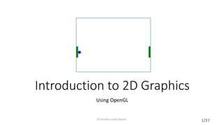
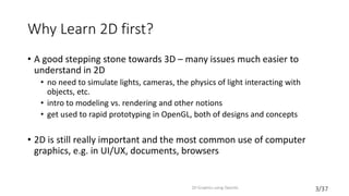
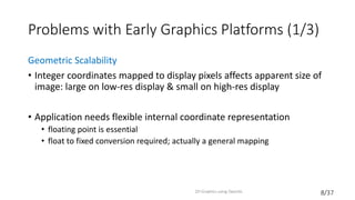
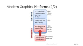
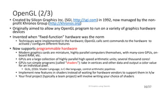
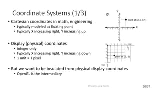
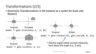
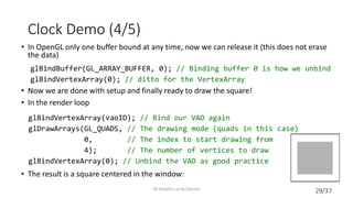
Clock Demo (1/5)
• Illustrate the use of OpenGL by going through step-by-step how to
create a simple clock application. First a bunch of setup before drawing
• Start by specifying vertex data for a square:
• Create a Vertex Buffer Object (VBO). This is essentially an array of data
stored in the GPU; we’ll copy vertex data to a VBO
2D Graphics using OpenGL
GLfloat vertexData[] = {
-.7, -.7, // Vertex 1
.7, -.7, // Vertex 2
.7, .7, // Vertex 3
-.7, .7, // Vertex 4
};
GLuint vboID; // Unsigned Integer
glGenBuffers(1, &vboID); // Generate 1 buffer (array); not initialized](https://image.slidesharecdn.com/lecture2-150915004939-lva1-app6892/85/2D-graphics-26-320.jpg)
![30/37
NXN✓
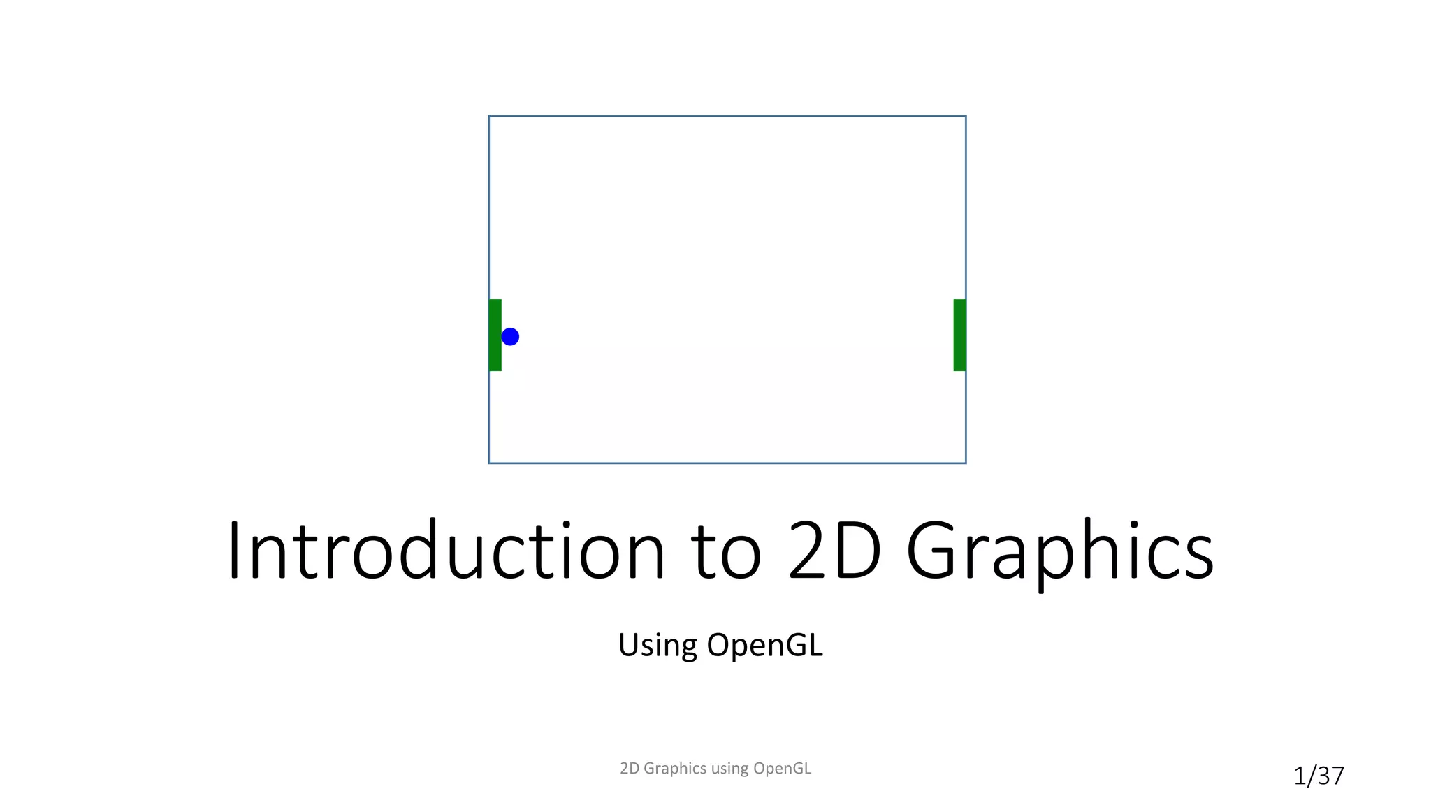
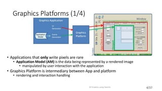
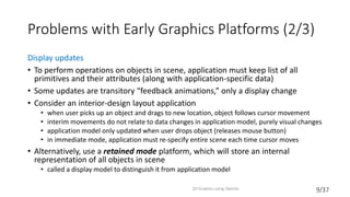
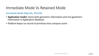
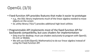
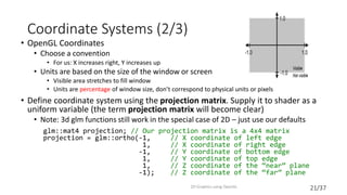
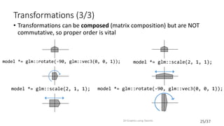
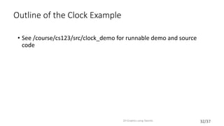
Winding Order
• Order is important: vertices must be specified in counter-clockwise order
relative to the viewer. Otherwise nothing shows up!
• Winding order determines the direction of the normal vector used in the “lighting
calculation”; if the normal is pointing the wrong way, we won’t see anything
• Counter-clockwise winding consistent with the “right-hand rule”
2D Graphics using OpenGL
GLfloat vertexData[] = {
-.7, -.7,
.7, -.7,
.7, .7,
-.7, .7, };
GLfloat vertexData[] = {
-.7, -.7,
-.7, .7,
.7, .7,
.7, -.7, };](https://image.slidesharecdn.com/lecture2-150915004939-lva1-app6892/85/2D-graphics-30-320.jpg)
![31/37
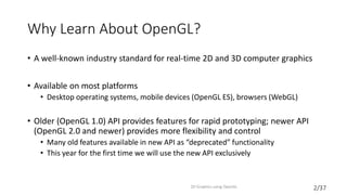
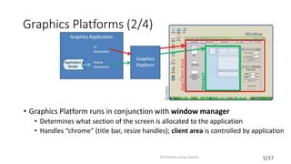
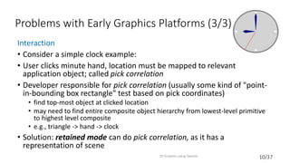
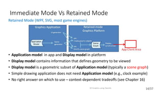
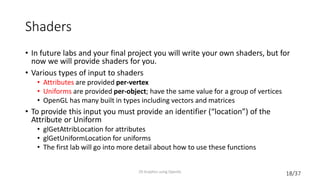
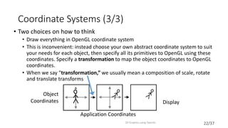
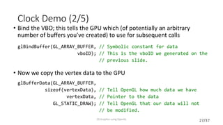
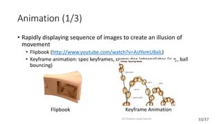
Clock Demo (5/5)
• We’ll draw a simplified hour hand using a quad rotated around the origin.
One could do the same thing to draw minute and second hands:
float hourAngle = -45; // Rotate 45 degrees clockwise
float width = .01, height = .4;
// Rotate around the Z axis
model *= glm::rotate(hourAngle, glm::vec3(0, 0, 1));
GLfloat hourVertexData[] = {
-width, 0,
width, 0,
width, height,
-width, height };
// Set up VBOs and VAOs as before
2D Graphics using OpenGL](https://image.slidesharecdn.com/lecture2-150915004939-lva1-app6892/85/2D-graphics-31-320.jpg)

This document provides an introduction to 2D graphics using OpenGL. It discusses why OpenGL is a useful industry standard API for 2D and 3D graphics. It explains that learning 2D graphics first is a good stepping stone towards 3D as many concepts are easier to understand in 2D without lights, cameras, etc. The document outlines some of the key components of graphics platforms, including retained vs immediate mode, and how early graphics platforms had limitations that modern ones address through features like hierarchical scenes and device independence. It then introduces OpenGL specifics like shaders, coordinate systems, transformations using matrices, and providing an example clock application to demonstrate drawing a simple 2D shape by setting up vertex buffers and rendering.


![[Android] 2D Graphics](https://cdn.slidesharecdn.com/ss_thumbnails/trainingandroidlesson12-130304083929-phpapp01-thumbnail.jpg?width=640&height=640&fit=bounds)