Downloaded 1,017 times
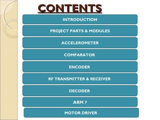
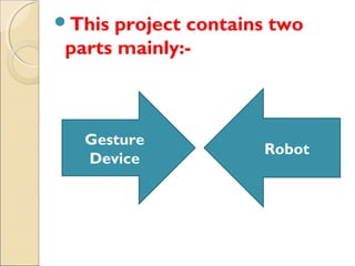
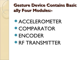
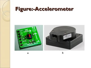
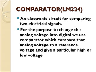
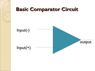
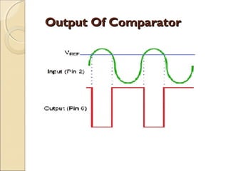
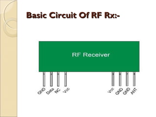
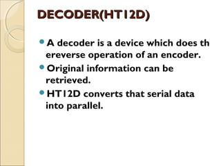
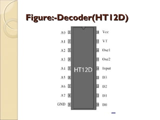
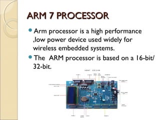


This document summarizes a seminar on controlling an industrial robotic arm using accelerometer-based gestures. The seminar covered: 1. A gesture-controlled robot that can be operated through hand gestures detected by a small transmitting device worn on the hand, containing an accelerometer. 2. The gesture device contains an accelerometer to detect motion, a comparator to convert analog signals to digital, an encoder to convert signals to radio format, and an RF transmitter to send commands wirelessly. 3. The robot contains an RF receiver to receive commands, a decoder to convert radio signals to motor commands, a microcontroller (ARM 7) to process commands, and a motor driver to operate the robotic arm.