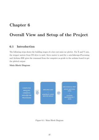
This document is the main project report for a 2D robotic plotter (CNC model) created by four students at the Government Engineering College Idukki. It describes the hardware and software used to build a 2D robotic plotter controlled by an Arduino microcontroller. The plotter uses stepper motors for the X and Y axes and a servo motor to control the pen. Software like Inkscape, CAMotics, Arduino IDE and Processing were used to design drawings, generate gcode files, and program the Arduino. The report provides details of the various components, software programs, and overall design and functioning of the 2D robotic plotter built as part of fulfilling B.Tech degree requirements.


![1.6 Motivation
Computer Numeric Control (CNC) refers to a wide variety of machines which are controlled
electronically and have many uses, including milling, drawing, extruding, cutting, and lathing.
CNC machines are really expensive. They are widely used in the fabrication of both electronic
and mechanical parts of large machines .So our group has decided to do a model to know about
theoretical and practical knowledge about this concept [2D Robotic Plotter].
1.7 Organisation of the Project
The report is organised as follows:
Abstract
Table of Contents
List of Figures
Chapter 1 : Introduction
Chapter 2 : Project Description
Chapter 3 : Software Description
Chapter 4 : Hardware Description
Chapter 5 : Mechanical Setup
Chapter 6 : Conclusion
References
Appendix
1.8 Conclusion
In this chapter,brief introduction of the project,literature review, motivation and organization
of the project has been prensented.
14](https://image.slidesharecdn.com/main2-160613124731/85/2D-ROBOTIC-PLOTTER-14-320.jpg)
![able through plug-ins (e.g., [Adobe [http://www.adobe.com/svg/viewer/install/, Ssrc SVG
[http://www.savarese.com/software/svgplugin/],and Google [http://www.google.com/chrome
frame]). Over a dozen companies including Apple (iPhone), Blackberry, LG, Motorola, Nokia,
Samsung, and Sony Ericsson produce mobile phones that utilize a subset of the full SVG stan-
dard (SVG Tiny) that has been tailored for devices with limited resources.
Inkscape is a free and open-source vector graphics editor; it can be used to create or edit
vector graphics such as illustrations, diagrams, line arts, charts, logos and complex paint-
ings. Inkscape’s primary vector graphics format is Scalable Vector Graphics (SVG) version
1.1. While Inkscape can import and export several formats, all editing workflow inevitably
occur within the guidelines of the SVG format.
Inkscape can render primitive vector shapes (e.g. rectangles, ellipses, polygons, arcs, spirals,
stars and isometric boxes), text and regions containing raster graphics. It also supports image
tracing, enabling the editor to create vector graphics from photos and other raster sources.
Created shapes can be subjected to further transformations, such as moving, rotating, scaling
and skewing. These objects may be filled with solid colors, patterns, radiant or linear color
gradient, their borders stroked or their transparency changed.
Inkscape SVG-based vector drawing program is useful for drawing:
• Illustrations for the Web.
• Graphics for mobile phones.
• Simple line drawings.
• Cartoons.
• Complex works of art.
• Figures for articles and books.
• Organization charts.
The file format that Inkscape uses is compact and quickly transmittable over the Internet. Yet
it is powerful and can describe complex drawings that are scalable to any size. Support for the
format has been added to web browsers and is already included in many mobile phones.
Inkscape supports the drawing of regular shapes (rectangles, circles, etc.), arbitrary paths, and
text. These objects can be given a wide variety of attributes such as color, gradient or pat-
terned fills, alpha blending, and markers. Objects can be transformed, cloned, and grouped.
Hyperlinks can be added for use in web browsers. The Inkscape program aims to be fully XML,
SVG, and CSS compliant.
Inkscape is available prepackaged for the Windows, Macintosh, and Linux operating systems.
19](https://image.slidesharecdn.com/main2-160613124731/85/2D-ROBOTIC-PLOTTER-19-320.jpg)
![The program and its source code are freely available. They can be obtained from the Inkscape
website [http://www.inkscape.org/].
Inkscape is undergoing very rapid development with new features being added and compliance
to the SVG standard being constantly improved.
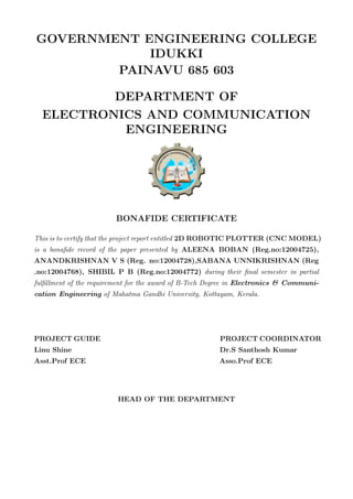
3.2.2 Inkscape Window
Start by opening Inkscape.This window contains several major areas, many containing clickable
icons or pull-down menus. The following figure shows this window and labels key parts.
The Command Bar, Snap Bar, Tool Controls, and Tool Box are detachable by dragging on the
handles (highlighted in blue) at the far left or top. They can be returned to their normal place
by dragging them back. New in v0.48: Some of the bars change position depending on which
option is selected at the bottom of the View menu. When Default is selected, the Command
Bar is on the top while the Snap Bar is on the right. When Custom is selected, the Command
Bar and the Snap Bar are both on the top. When Wide is selected, the Command Bar and
the Snap Bar are both on the right. By default, Default is used if you are not using a “Wide
Screen” display while Wide is used if you are. A width to height aspect ratio of greater than
1.65 is defined to be wide. These bars, as well as the Palette and Status Bar, can be hidden
using the View Show/Hide submenu.
As Inkscape has grown more complex, the area required to include icons and entry boxes for all
the various items has also grown leading to problems when Inkscape is used on small screens.
The Command Bar, Snap Bar, Tool Controls, and Tool Box have variable widths or heights.
If there are too many items to be shown in the width (height) of the Inkscape window, a small
down arrow will appear on the right side or bottom of the bars. Clicking on this arrow will
open a drop-down menu with access to the missing items.
20](https://image.slidesharecdn.com/main2-160613124731/85/2D-ROBOTIC-PLOTTER-20-320.jpg)
![Figure 3.1: Inkscape Window
3.2.3 Inkscape Program
Inkscape has its roots in the program Gill (GNOME Illustrator application) created by Raph
Levian [http:// www.levien.com/] of Ghostscript fame. This project was expanded on by the
Sodipodi [http://sourceforge.net/projects/ sodipodi] program. A different set of goals led to
the split-off of the current Inkscape development effort.
The goal of the writers of Inkscape is to produce a program that can take full advantage of the
SVG standard. This is not a small task. A link to the road map for future development can
be found on the Inkscape website [http:// www.inkscape.org/].
Instructions on installing Inkscape can be found on the Inkscape website. Full functionality
of Inkscape requires additional helper programs to be installed, especially for importing and
exporting files in different graphic formats.
In this project the use of inkscape is to convert any image(formats) into graphics
code usually known as GCODE. .GCODE formats are generated by integrating
inkscape with necessary extension files.
3.2.4 Generating gcode files using inkscape
1. Download and install Inkscape 0.48.5 version.
2. Install an Add-on that enables the export images to gcode files.
3. Open the Inkscape, go to File menu and click ”Document Properties”.
4. Change the custom size.
21](https://image.slidesharecdn.com/main2-160613124731/85/2D-ROBOTIC-PLOTTER-21-320.jpg)
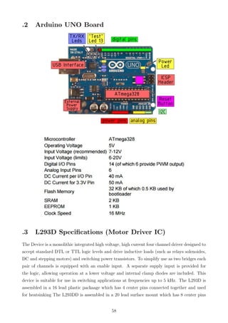
![3.4 Arduino IDE
The Arduino project provides the Arduino integrated development environment (IDE), which
is a cross-platform application written in the programming language Java. It originated from
the IDE for the languages Processing and Wiring. It is designed to introduce programming to
artists and other newcomers unfamiliar with software development. It includes a code editor
with features such as syntax highlighting, brace matching, and automatic indentation, and
provides simple one-click mechanism to compile and load programs to an Arduino board. A
program written with the IDE for Arduino is called a ”sketch”.
The Arduino IDE supports the languages C and C++ using special rules to organize code. The
Arduino IDE supplies a software library called Wiring from the Wiring project, which provides
many common input and output procedures. A typical Arduino C/C++ sketch consist of two
functions that are compiled and linked with a program stub main() into an executable cyclic
executive program:[.2cm]
• setup(): a function that runs once at the start of a program and that can initialize
settings.
• loop(): a function called repeatedly until the board powers off.
After compiling and linking with the GNU toolchain, also included with the IDE distribution,
the Arduino IDE employs the program avrdude to convert the executable code into a text
file in hexadecimal coding that is loaded into the Arduino board by a loader program in the
board’s firmware.
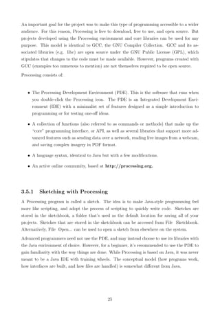
3.5 Processing 3.0.2
Processing is a simple programming environment that was created to make it easier to develop
visually oriented applications with an emphasis on animation and providing users with instant
feedback through interaction. The developers wanted a means to “sketch” ideas in code. As
its capabilities have expanded over the past decade, Processing has come to be used for more
advanced production-level work in addition to its sketching role. Originally built as a domain-
specific extension to Java targeted towards artists and designers, Processing has evolved into a
full-blown design and prototyping tool used for large-scale installation work, motion graphics,
and complex data visualization.
Processing is based on Java, but because program elements in Processing are fairly simple,
you can learn to use it even if you don’t know any Java. If you’re familiar with Java,
it’s best to forget that Processing has anything to do with Java for a while, until you get
the hang of how the API works. The latest version of Processing can be downloaded at
http://processing.org/download.
24](https://image.slidesharecdn.com/main2-160613124731/85/2D-ROBOTIC-PLOTTER-24-320.jpg)
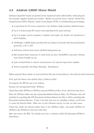
![[12pt,a4paper]report [top=0.80in, bottom=0.80in, left=0.8in,right=0.80in]geometry [utf8]inputenc
graphicx ragged2e
43](https://image.slidesharecdn.com/main2-160613124731/85/2D-ROBOTIC-PLOTTER-43-320.jpg)
![Serial.print(Ymax);
Serial.println(" mm.");
}
/**********************
* void loop() - Main loop
***********************/
void loop()
{
delay(200);
char line[ LINE_BUFFER_LENGTH ];
char c;
int lineIndex;
bool lineIsComment, lineSemiColon;
lineIndex = 0;
lineSemiColon = false;
lineIsComment = false;
while (1) {
// Serial reception - Mostly from Grbl, added semicolon support
while ( Serial.available()>0 ) {
c = Serial.read();
if (( c == ’n’) || (c == ’r’) ) { // End of line reached
if ( lineIndex > 0 ) { // Line is complete. Then execute!
line[ lineIndex ] = ’0’; // Terminate string
if (verbose) {
Serial.print( "Received : ");
Serial.println( line );
}
processIncomingLine( line, lineIndex );
lineIndex = 0;
}
else {
// Empty or comment line. Skip block.
}
lineIsComment = false;
lineSemiColon = false;
Serial.println("ok");
}
47](https://image.slidesharecdn.com/main2-160613124731/85/2D-ROBOTIC-PLOTTER-47-320.jpg)
![else {
if ( (lineIsComment) || (lineSemiColon) ) { // Throw away all comment characters
if ( c == ’)’ ) lineIsComment = false; // End of comment. Resume line.
}
else {
if ( c <= ’ ’ ) { // Throw away whitepace and control character
}
else if ( c == ’/’ ) { // Block delete not supported. Ignore charact
}
else if ( c == ’(’ ) { // Enable comments flag and ignore all charac
lineIsComment = true;
}
else if ( c == ’;’ ) {
lineSemiColon = true;
}
else if ( lineIndex >= LINE_BUFFER_LENGTH-1 ) {
Serial.println( "ERROR - lineBuffer overflow" );
lineIsComment = false;
lineSemiColon = false;
}
else if ( c >= ’a’ && c <= ’z’ ) { // Upcase lowercase
line[ lineIndex++ ] = c-’a’+’A’;
}
else {
line[ lineIndex++ ] = c;
}
}
}
}
}
}
void processIncomingLine( char* line, int charNB ) {
int currentIndex = 0;
char buffer[ 64 ]; // Hope that 64 is enough for 1 parameter
struct point newPos;
newPos.x = 0.0;
newPos.y = 0.0;
while( currentIndex < charNB ) {
48](https://image.slidesharecdn.com/main2-160613124731/85/2D-ROBOTIC-PLOTTER-48-320.jpg)
![switch ( line[ currentIndex++ ] ) { // Select command, if any
case ’U’:
penUp();
break;
case ’D’:
penDown();
break;
case ’G’:
buffer[0] = line[ currentIndex++ ]; // /! Dirty - Only works with 2 digit com
// buffer[1] = line[ currentIndex++ ];
// buffer[2] = ’0’;
buffer[1] = ’0’;
switch ( atoi( buffer ) ){// Select G command
case 0: // G00 & G01 - Movement or fast movement. Same here
case 1:
// /! Dirty - Suppose that X is before Y
char* indexX = strchr( line+currentIndex, ’X’ );
char* indexY = strchr( line+currentIndex, ’Y’ );
if ( indexY <= 0 ) {
newPos.x = atof( indexX + 1);
newPos.y = actuatorPos.y;
}
else if ( indexX <= 0 ) {
newPos.y = atof( indexY + 1);
newPos.x = actuatorPos.x;
}
else {
newPos.y = atof( indexY + 1);
indexY = ’0’;
newPos.x = atof( indexX + 1);
}
drawLine(newPos.x, newPos.y );
// Serial.println("ok");
actuatorPos.x = newPos.x;
actuatorPos.y = newPos.y;
break;
}
break;
49](https://image.slidesharecdn.com/main2-160613124731/85/2D-ROBOTIC-PLOTTER-49-320.jpg)
![case ’M’:
buffer[0] = line[ currentIndex++ ];// /! Dirty - Only works with 3 digit commands
buffer[1] = line[ currentIndex++ ];
buffer[2] = line[ currentIndex++ ];
buffer[3] = ’0’;
switch ( atoi( buffer ) ){
case 300:
{
char* indexS = strchr( line+currentIndex, ’S’ );
float Spos = atof( indexS + 1);
// Serial.println("ok");
if (Spos == 30) {
penDown();
}
if (Spos == 50) {
penUp();
}
break;
}
case 114: // M114 - Repport position
Serial.print( "Absolute position : X = " );
Serial.print( actuatorPos.x );
Serial.print( " - Y = " );
Serial.println( actuatorPos.y );
break;
default:
Serial.print( "Command not recognized : M");
Serial.println( buffer );
}
}
}
}
/*********************************
* Draw a line from (x0;y0) to (x1;y1).
* int (x1;y1) : Starting coordinates
* int (x2;y2) : Ending coordinates
**********************************/
void drawLine(float x1, float y1) {
50](https://image.slidesharecdn.com/main2-160613124731/85/2D-ROBOTIC-PLOTTER-50-320.jpg)
![digitalWrite(15, HIGH);
digitalWrite(16, LOW);
if (verbose) {
Serial.println("Pen down.");
}
}
*//Program used in Processing for loading Gcode//*
import java.awt.event.KeyEvent;
import javax.swing.JOptionPane;
import processing.serial.*;
Serial port = null;
// select and modify the appropriate line for your operating system
// leave as null to use interactive port (press ’p’ in the program)
String portname = null;
//String portname = Serial.list()[0]; // Mac OS X
//String portname = "/dev/ttyUSB0"; // Linux
//String portname = "COM6"; // Windows
boolean streaming = false;
float speed = 0.001;
String[] gcode;
int i = 0;
void openSerialPort()
{
if (portname == null) return;
if (port != null) port.stop();
port = new Serial(this, portname, 9600);
port.bufferUntil(’n’);
}
void selectSerialPort()
{
54](https://image.slidesharecdn.com/main2-160613124731/85/2D-ROBOTIC-PLOTTER-54-320.jpg)
![println("Window was closed or the user hit cancel.");
} else {
println("User selected " + selection.getAbsolutePath());
gcode = loadStrings(selection.getAbsolutePath());
if (gcode == null) return;
streaming = true;
stream();
}
}
void stream()
{
if (!streaming) return;
while (true) {
if (i == gcode.length) {
streaming = false;
return;
}
if (gcode[i].trim().length() == 0) i++;
else break;
}
println(gcode[i]);
port.write(gcode[i] + ’n’);
i++;
}
void serialEvent(Serial p)
{
String s = p.readStringUntil(’n’);
println(s.trim());
if (s.trim().startsWith("ok")) stream();
if (s.trim().startsWith("error")) stream(); // XXX: really?
}
57](https://image.slidesharecdn.com/main2-160613124731/85/2D-ROBOTIC-PLOTTER-57-320.jpg)