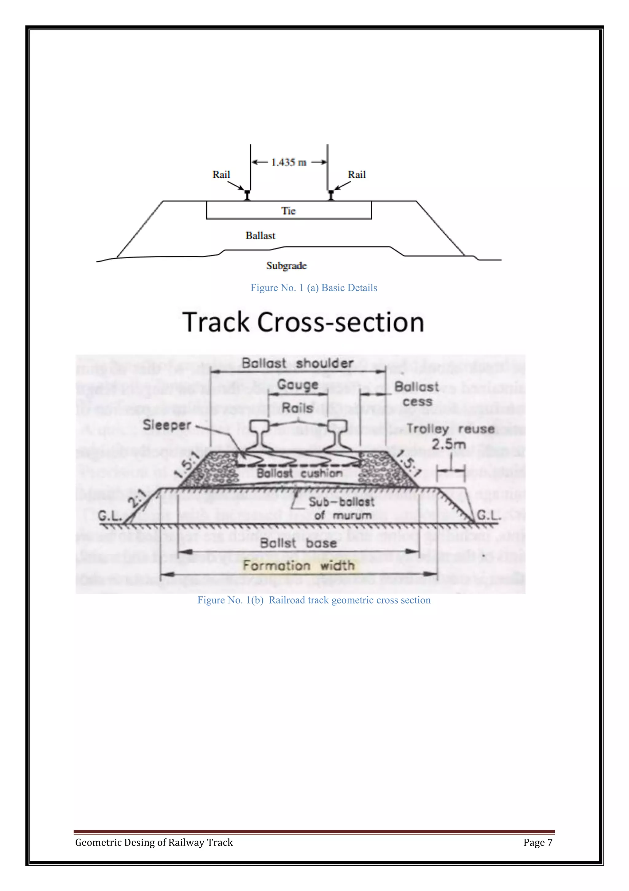
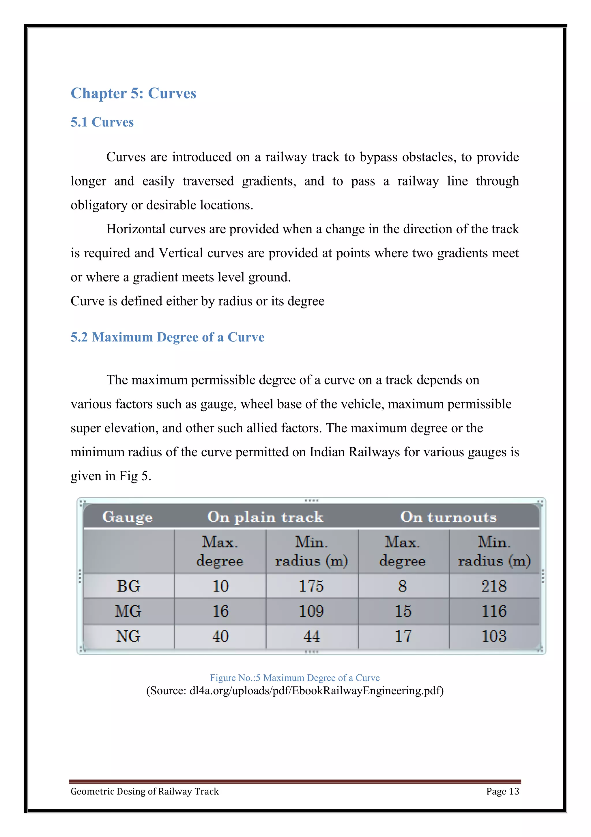
SlideShare a Scribd company logo
2017
Mohit M. Jain
M.jain
3/18/2017
Geometric Design Of Railway Track
Geometric Desing of Railway Track Page 1
GUJARAT TECHNOLOGICAL UNIVERSITY
Chandkheda, Ahmedabad
A Project Report
On
“Geometric Design Of Railway Track”
Under subject of
RAILWAY, BRIDGE & TUNNEL ENGINEERING
(2160603)
Submitted by:
Mohit M. Jain
140420106025
Guided By:
Prof. Vishwa Mehta
(Faculty Guide)
Department of Civil Engineering
Sarvajanik College of Engineering &Technology,
Athwalines, Surat.
Geometric Desing of Railway Track Page 2
SARVAJANIK COLLEGE OF ENGINEERING & TECHNOLOGY,
ATHWALINES, SURAT.
CIVIL ENGINEERING DEPARTMENT
CERTIFICATE
Date:
This is to certify that the Report entitled “ Geometric Design Of Railway
Track” has been carried out by Jain Mohit(140420106025). Under my
guidance in fulfilment of the Degree of B.E. in Civil Engineering (6rd
semester)
of Gujarat Technological University, Ahmadabad during the academic year
2015-16.
Prof. Vishwa Mehta Prof. Pratima Patel
(Faculty Guide) Associate Professor & Head,
Civil Engineering Department Civil Engineering Department
EXTERNAL EXAMINER
Geometric Desing of Railway Track Page 3
ACKNOWLEDGEMENT
Behind every success there are lot many efforts, but efforts are fruitful
due to hands making the passage smoother. We express our deep sense of
gratitude for hands, people extended to us during our work.
Research brings about dramatic changes in the traditional look out of
science & technology. It is continuous phenomenon under taken by one and
every throughout the world. It has widened our vision, opened newer avenues
and lightened the dark obscure facets of mysteries universe. The work depicted
in this thesis is a bucketful of contribution to the large ocean of research
occurring globally. As one flower makes no garland, this presentation would not
have taken shape without wholehearted encouragement and live involvement of
some generous souls.
We express sincere and heartfelt thanks to Dr.Vaishali Mungurwadi,
Principal, and Associate Professor Pratima Patil, (Head of Civil Engineering
Department), Sarvajanik College Of Engineering & Technology for giving us
an opportunity to undertake this research subject for study.
We express a deep sense of gratitude to my guide Prof. Vishwa Mehta, Civil
Engineering Department, Sarvajanik College Of Engineering & Technology
for her constructive support, constant encouragement, guidance and challenging
our efforts in the right direction without which this thesis would not have
attained the present form.
Geometric Desing of Railway Track Page 4
Contents
Chapter 1: Introduction .............................................................................................................. 5
1.1 Introduction ................................................................................................................. 5
Chapter 2: Necessity................................................................................................................... 6
2.1 Necessity........................................................................................................................... 6
Chapter 3: GEOMETRIC CROSS SECTION ........................................................................... 6
3.1 CrossSection ..................................................................................................................... 6
Chapter 4: Gradients................................................................................................................... 8
4.1 Gradient............................................................................................................................. 8
4.2 Types of gradients............................................................................................................. 8
4.2. (a) Ruling Gradient .......................................................................................................... 9
4.2. (b) Pusher or Helper Gradient........................................................................................ 10
4.2. (c) Momentum gradient ................................................................................................. 10
4.2. (d) Gradients in station yards......................................................................................... 11
4.2. (e) Grade Compensation on Curves............................................................................... 12
Chapter 5: Curves..................................................................................................................... 13
5.1 Curves ............................................................................................................................. 13
5.2 Maximum Degree of a Curve ......................................................................................... 13
Chapter 6: Superelevation........................................................................................................ 14
6.1 Superelevation................................................................................................................. 14
6.2 Objective Of Providing Superelevation.......................................................................... 14
6.3 Centrifugal Force on a Curved Track ............................................................................. 14
6.4 Formula for Superelevation ............................................................................................ 16
6.5 Thumb Rules for Calculating Superelevation in the Field.............................................. 16
6.6 Types of Cant.................................................................................................................. 17
6.6.1 Equilibrium cant........................................................................................................... 17
6.6.2 Cant deficiency ( Cd ).................................................................................................. 17
6.6.3 Cant excess ( Ce ) ........................................................................................................ 17
Chapter 7: Widening of Gauge on Curve................................................................................. 18
7.1 Widening of Gauge on Curve.................................................................................... 18
Geometric Desing of Railway Track Page 5
Chapter 1: Introduction
1.1 Introduction
Geometric design for transportation facilities includes the design of
geometric cross sections, horizontal alignment, vertical alignment, intersections,
and various design details. These basic elements are common to all linear
facilities, such as roadways, railways, and airport runways and taxiways.
Although the details of design standards vary with the mode and the class of
facility, most of the issues involved in geometric design are similar for all
modes. In all cases, the goals of geometric design are to maximize the comfort,
safety, and economy of facilities, while minimizing their environmental
impacts. This chapter focuses on the fundamentals of geometric design, and
presents standards and examples from different modes.
The order of presentation of material in this chapter is to consider
geometric cross sections first, then vertical alignment, horizontal alignment,
super elevation , and various design details. For purposes of exposition, the
order of the topics is not very important. In a typical design project, on the other
hand, there is a definite order of tasks, in which the establishment of a tentative
horizontal centreline usually precedes establishment of vertical alignment. This
is because the elevation of the existing ground along the centreline is an
important consideration in establishing the vertical alignment. The process of
designing the vertical alignment begins with plotting a profile of the existing
terrain, and a tentative horizontal centreline must already be established in order
to do this.
Geometric Desing of Railway Track Page 6
Chapter 2: Necessity
2.1 Necessity
 The need for proper geometric design of a track arises because of the
following considerations :
o To ensure the smooth and safe running of trains
o To achieve maximum speeds
o To carry heavy axle loads
o To avoid accidents and derailments due to a defective permanent
way
o To ensure that the track requires least maintenance.
o For good aesthetics
Chapter 3: GEOMETRIC CROSS SECTION
3.1 Cross Section
The primary consideration in the design of geometric cross sections for
highways, runways, and taxiways is drainage. Details vary depending on the
type of facility and agency.
Railway cross sections are as shown in Fig.1. The distance between the
rails, as shown in the figure, is what is known as standard gage in North
America. Other gauges are sometimes used. In the case of railroad track, the
shape of the cross section is not intended to provide drainage, since the ballast,
which is permeable material, serves this purpose.
Geometric Desing of Railway Track Page 7
Figure No. 1 (a) Basic Details
Figure No. 1(b) Railroad track geometric cross section
Geometric Desing of Railway Track Page 8
Chapter 4: Gradients
4.1 Gradient
Gradients are provided to negotiate the rise or fall in the level of the
railway track. A rising gradient is one in which the track rises in the direction of
the movement of traffic and a down or falling gradient is one in which the track
loses elevation in the direction of the movement of traffic. A gradient is
normally represented by the distance travelled for a rise or fall of one unit.
Sometimes the gradient is indicated as per cent rise or fall. For example, if there
is a rise of 1 m in 400 m, the gradient is 1 in 400 or 0.25%, as shown in
Fig.2.
Figure No.:2 Rising and falling gradient
Gradients are provided to meet the following objectives.
(a) To reach various stations at different elevations
(b) To follow the natural contours of the ground to the extent possible
(c) To reduce the cost of earthwork.
4.2 Types of gradients.
(a) Ruling gradient
(b) Pusher or helper gradient
(c) Momentum gradient
(d) Gradients in station yards
Geometric Desing of Railway Track Page 9
4.2. (a) Ruling Gradient
The ruling gradient is the steepest gradient that exists in a section. It
determines the maximum load that can be hauled by a locomotive on that
section. While deciding the ruling gradient of a section, it is not only the
severity of the gradient but also its length as well as its position with respect to
the gradients on both sides that have to be taken into consideration. The power
of the locomotive to be put into service on the track also plays an important role
in taking this decision, as the locomotive should have adequate power to haul
the entire load over the ruling gradient at the maximum permissible speed.
The extra force P required by a locomotive to pull a train of weight W on
a gradient with an angle of inclination θ is , Rising gradient 1 in 400 (0.25%)
Falling gradient (0.25%) 1 on 400
P = W Sinθ
= W tanθ (approximately, as θ is very small)
= W × gradient
Indian Railways does not specify any fixed ruling gradient owing to
enormous variations in the topography of the country, the traffic plying on
various routes, and the speed and type of locomotive in use on various sections.
Generally, the following ruling gradients are adopted on Indian Railways when
there is only one locomotive pulling the train.
In plain terrain: 1 in 150 to 1 in 250
In hilly terrain: 1 in 100 to 1 in 150
Once a ruling gradient has been specified for a section, all other gradients
provided in that section should be flatter than the ruling gradient after making
due compensation for curvature.
Geometric Desing of Railway Track Page 10
Figure No.:3 Ruling Gradient
4.2. (b) Pusher or Helper Gradient
In hilly areas, the rate of rise of the terrain becomes very important when
trying to reduce the length of the railway line and, therefore, sometimes
gradients steeper than the ruling gradient are provided to reduce the overall cost.
In such situations, one locomotive is not adequate to pull the entire load, and an
extra locomotive is required.
When the gradient of the ensuing section is so steep as to necessitate the
use of an extra engine for pushing the train, it is known as a pusher or helper
gradient. Examples of pusher gradients are the Budni–Barkhera section of
Central Railways and the Darjeeling Himalayan Railway section.
4.2. (c) Momentum gradient
The momentum gradient is steeper than the ruling gradient and can be
overcome by a train because of the momentum it gathers while running on the
section. In valleys, a falling gradient is sometimes followed by a rising gradient.
In such a situation, a train coming down a falling gradient acquires good speed
and momentum, which gives additional kinetic energy to the train and allows it
to negotiate gradients steeper than the ruling gradient. In sections with
momentum gradients there are no obstacles provided in the form of signals, etc.,
which may bring the train to a critical juncture
Geometric Desing of Railway Track Page 11
Figure No.:4 Momentum gradient
4.2. (d) Gradients in station yards
The gradients in station yards are quite flat due to the following reasons.
(a) To prevent standing vehicles from rolling and moving away from the
yard due to the combined effect of gravity and strong winds.
(b) To reduce the additional resistive forces required to start a locomotive
to the extent possible.
It may be mentioned here that generally, yards are not levelled completely and
certain flat gradients are provided in order to ensure good drainage. The
maximum gradient prescribed in station yards on Indian Railways is 1 in 400,
while the recommended gradient is 1 in 1000.
Geometric Desing of Railway Track Page 12
4.2. (e) Grade Compensation on Curves
Curves provide extra resistance to the movement of trains. As a result, gradients
are compensated to the following extent on curves:
(a) On BG tracks, 0.04% per degree of the curve or 70/R, whichever is
minimum.
(b) On MG tracks, 0.03% per degree of curve or 52.5/R, whichever is
minimum.
(c) On NG tracks, 0.02% per degree of curve or 35/R, whichever is
minimum where R is the radius of the curve in metres.
The gradient of a curved portion of the section should be flatter than the ruling
gradient because of the extra resistance offered by the curve.
Example:
Find the steepest gradient on a 2° curve for a BG line with a ruling gradient of 1
in 200.
Solution
(i) Ruling gradient = 1 in 200 = 0.5%
(ii) Compensation for a 2° curve = 0.04 × 2 = 0.08%
(iii) Compensated gradient = 0.5 – 0.08 = 0.42% = 1 in 238
The steepest gradient on the curved track is 1 in 238.
Geometric Desing of Railway Track Page 13
Chapter 5: Curves
5.1 Curves
Curves are introduced on a railway track to bypass obstacles, to provide
longer and easily traversed gradients, and to pass a railway line through
obligatory or desirable locations.
Horizontal curves are provided when a change in the direction of the track
is required and Vertical curves are provided at points where two gradients meet
or where a gradient meets level ground.
Curve is defined either by radius or its degree
5.2 Maximum Degree of a Curve
The maximum permissible degree of a curve on a track depends on
various factors such as gauge, wheel base of the vehicle, maximum permissible
super elevation, and other such allied factors. The maximum degree or the
minimum radius of the curve permitted on Indian Railways for various gauges is
given in Fig 5.
Figure No.:5 Maximum Degree of a Curve
(Source: dl4a.org/uploads/pdf/EbookRailwayEngineering.pdf)
Geometric Desing of Railway Track Page 14
Chapter 6: Superelevation
6.1 Superelevation
The following terms are frequently used in the design of horizontal
curves. Superelevation or cant (Ca) is the difference in height between the outer
and the inner rail on a curve. It is provided by gradually lifting the outer rail
above the level of the inner rail. The inner rail is taken as the reference rail and
is normally maintained at its original level. The inner rail is also known as the
gradient rail.
6.2 Objective Of Providing Superelevation
The main functions of superelevation are the following :
(a) To ensure a better distribution of load on both rails
(b) To reduce the wear and tear of the rails and rolling stock
(c) To neutralize the effect of lateral forces
(d) To provide comfort to passengers
6.3 Centrifugal Force on a Curved Track
A vehicle has a tendency to travel in a straight direction, which is
tangential to the curve, even when it moves on a circular curve. As a result, the
vehicle is subjected to a constant radial acceleration:
Radial acceleration = g = V2
/R
Where, V = velocity (metres per second) and
R = Radius of curve (metres).
This radial acceleration produces a centrifugal force which acts in a radial
direction away from the centre.
Geometric Desing of Railway Track Page 15
The value of the centrifugal force is given by the formula
Force = mass × acceleration
F = m × (V2
/R)
= (W/g) × (V2 /R)
Where, F = Centrifugal force (tonnes),
W = Weight of the vehicle (tonnes),
V = Speed (metre/sec),
g = Acceleration due to gravity (metre/sec2 ), and
R = Radius of the curve (metres).
To counteract the effect of the centrifugal force, the outer rail of the curve
is elevated with respect to the inner rail by an amount equal to the
superelevation. A state of equilibrium is reached when both the wheels exert
equal pressure on the rails and the superelevation is enough to bring the
resultant of the centrifugal force and the force exerted by the weight of the
vehicle at right angles to the plane of the top surface of the rails. In this state of
equilibrium, the difference in the heights of the outer and inner rails of the curve
known as equilibrium superelevation.
Figure No.:6 Centrifugal Force
Geometric Desing of Railway Track Page 16
6.4 Formula for Superelevation
The θ is the angle that the inclined plane makes with the horizontal line, then
where ,
e = Superelevation,
G= Gauge,
V = Velocity,
g = Acceleration due to gravity, and
R = Radius of the curve.
6.5 Thumb Rules for Calculating Superelevation in the Field
A field engineer can adopt the following thumb rules for determining the
superelevation of any curve
Geometric Desing of Railway Track Page 17
 Super elevation for BG in cm
 For MG tracks
 Super elevation = three-fifths of the above formula
 The equilibrium speed is used in this formula
6.6 Types of Cant
The cant are further divided on the bases of speed:
 Equilibrium cant
 Cant deficiency ( Cd )
 Cant excess ( Ce )
6.6.1 Equilibrium cant
Value of super elevation derived from the equation using equilibrium speed
6.6.2 Cant deficiency ( Cd )
Cant deficiency (Cd) occurs when a train travels around a curve at a speed
higher than the equilibrium speed. It is the difference between the theoretical
cant required for such high speeds and the actual cant provided. Maximum
permissible Cd : 7.6cm (BG), 5.1cm (MG), 3.8cm (NG).
6.6.3 Cant excess ( Ce )
Cant excess (Ce) occurs when a train travels around a curve at a speed lower
than the equilibrium speed. It is the difference between the actual cant provided
and the theoretical cant required for such a low speed.
Geometric Desing of Railway Track Page 18
Chapter 7: Widening of Gauge on Curve
7.1Widening of Gauge on Curve
When vehicle moves onto a curve, the flange of the outside wheel of the
leading axle continues to travel in a straight line till it rubs against the rail. Due
to the coning of wheels ,the outside wheel travels a longer distance compared to
the inner wheel. In an effort to make up for the difference in the distance
travelled by the outer wheel and the inner wheel, the inside wheels slip
backward and the outer wheels skid forward.
The widening of the gauge on a curve has, in fact, tends to decrease the wear
and tear on both the wheel and the track
The widening of the gauge on curves can be calculated using the formula
 Extra width on curves
 w = 13(B+L)2
/R
 Where,
 B is the wheel base of the vehicle in metres,
 R is the radius of the curve in metres,
 L =0.02(h2
+ Dh)1/2
is the lap of the flange in metres,
 h is the depth of flange below top of the rail(cm),
 D is the diameter of the wheel of the vehicle (cm).
Geometric Desing of Railway Track Page 19
Figure No.:7 Widening of Gauge on Curve
(Source:www.indianrailways.gov.in/railwayboard/uploads/codesmanual/IRPWM/Permanent
WayManual)
Geometric Desing of Railway Track Page 20
Chapter 8: References
 http://dl4a.org/uploads/pdf/EbookRailwayEngineering
 http://trainguard.in/horizontalcurve&submit&posttypeproduct
 http://www.indianrailways.gov.in/railwayboard/uploads/codesmanual/IR
PWM/PermanentWayManual
 http://teacher.buet.ac.bd/cfc/curve

More Related Content

What's hot

Railway Engineering - Geometric design of track
Railway Engineering - Geometric design of trackRailway Engineering - Geometric design of track
Railway Engineering - Geometric design of track
Mani Vel
 
Station and Yards in Indian Railway
Station and Yards in Indian RailwayStation and Yards in Indian Railway
Station and Yards in Indian Railway
Arbaz Kazi
 
Railway engineering
Railway engineeringRailway engineering
Railway engineering
Shanmugaraj M
 
Highway Cross-sectional Elements
Highway Cross-sectional ElementsHighway Cross-sectional Elements
Highway Cross-sectional Elements
AkshathaBhandary
 
Site distance in highway engineering
Site distance in highway engineeringSite distance in highway engineering
Site distance in highway engineering
tirath prajapati
 
Transition curve and Superelevation
Transition curve and SuperelevationTransition curve and Superelevation
Transition curve and Superelevation
Mir Zafarullah
 
transition curve in Highway Geometry Design
transition curve in Highway Geometry Designtransition curve in Highway Geometry Design
transition curve in Highway Geometry Design
Nachiketa Mithaiwala
 
Railway station and YARD
Railway station and YARD Railway station and YARD
Railway station and YARD
Dhruv Makadia
 
3.alignment of railway lines
3.alignment of railway lines3.alignment of railway lines
3.alignment of railway lines
Mani Vel
 
Design of curves
Design of curvesDesign of curves
Design of curves
Dolat Ram
 
Points and crossings
Points and crossingsPoints and crossings
Points and crossings
srinivas2036
 
Highway Horizontal Alignment
Highway Horizontal AlignmentHighway Horizontal Alignment
Highway Horizontal Alignment
AkshathaBhandary
 
Stations and Yards of Railway
Stations and Yards of RailwayStations and Yards of Railway
Stations and Yards of Railway
Souvik Mondal
 
Alignment of railway tracks
Alignment of railway tracksAlignment of railway tracks
Alignment of railway tracks
Gowtham G
 
Geometric Design - Horizontal and vertical curves
Geometric Design - Horizontal and vertical curvesGeometric Design - Horizontal and vertical curves
Geometric Design - Horizontal and vertical curves
sachin dass
 
highway engineering/ transportation engineering-I
highway engineering/ transportation engineering-Ihighway engineering/ transportation engineering-I
highway engineering/ transportation engineering-I
Subrat Padhy
 
Components of railway track
Components of railway trackComponents of railway track
Components of railway track
gayathrysatheesan1
 
Highway Alignment
Highway AlignmentHighway Alignment
Highway Alignment
AkshathaBhandary
 
Presentation on railway construction and maintenance
Presentation on railway construction and maintenancePresentation on railway construction and maintenance
Presentation on railway construction and maintenance
Mohd Bakhsh
 

What's hot (20)

Railway Engineering - Geometric design of track
Railway Engineering - Geometric design of trackRailway Engineering - Geometric design of track
Railway Engineering - Geometric design of track
 
Station and Yards in Indian Railway
Station and Yards in Indian RailwayStation and Yards in Indian Railway
Station and Yards in Indian Railway
 
Railway engineering
Railway engineeringRailway engineering
Railway engineering
 
Highway Cross-sectional Elements
Highway Cross-sectional ElementsHighway Cross-sectional Elements
Highway Cross-sectional Elements
 
Site distance in highway engineering
Site distance in highway engineeringSite distance in highway engineering
Site distance in highway engineering
 
Transition curve and Superelevation
Transition curve and SuperelevationTransition curve and Superelevation
Transition curve and Superelevation
 
transition curve in Highway Geometry Design
transition curve in Highway Geometry Designtransition curve in Highway Geometry Design
transition curve in Highway Geometry Design
 
Railway station and YARD
Railway station and YARD Railway station and YARD
Railway station and YARD
 
3.alignment of railway lines
3.alignment of railway lines3.alignment of railway lines
3.alignment of railway lines
 
Design of curves
Design of curvesDesign of curves
Design of curves
 
Points and crossings
Points and crossingsPoints and crossings
Points and crossings
 
Highway Horizontal Alignment
Highway Horizontal AlignmentHighway Horizontal Alignment
Highway Horizontal Alignment
 
Stations and Yards of Railway
Stations and Yards of RailwayStations and Yards of Railway
Stations and Yards of Railway
 
Alignment of railway tracks
Alignment of railway tracksAlignment of railway tracks
Alignment of railway tracks
 
Geometric Design - Horizontal and vertical curves
Geometric Design - Horizontal and vertical curvesGeometric Design - Horizontal and vertical curves
Geometric Design - Horizontal and vertical curves
 
highway engineering/ transportation engineering-I
highway engineering/ transportation engineering-Ihighway engineering/ transportation engineering-I
highway engineering/ transportation engineering-I
 
Components of railway track
Components of railway trackComponents of railway track
Components of railway track
 
Left hand turnout
Left hand turnoutLeft hand turnout
Left hand turnout
 
Highway Alignment
Highway AlignmentHighway Alignment
Highway Alignment
 
Presentation on railway construction and maintenance
Presentation on railway construction and maintenancePresentation on railway construction and maintenance
Presentation on railway construction and maintenance
 

Viewers also liked

Railway engineering
Railway engineeringRailway engineering
Railway engineering
hiranrathva
 
Surface runoff
Surface runoffSurface runoff
Surface runoff
Mohsin Siddique
 
Ch5 Plate Girder Bridges (Steel Bridges تصميم الكباري المعدنية & Prof. Dr. Me...
Ch5 Plate Girder Bridges (Steel Bridges تصميم الكباري المعدنية & Prof. Dr. Me...Ch5 Plate Girder Bridges (Steel Bridges تصميم الكباري المعدنية & Prof. Dr. Me...
Ch5 Plate Girder Bridges (Steel Bridges تصميم الكباري المعدنية & Prof. Dr. Me...
Hossam Shafiq II
 
Points and crossings
Points and crossingsPoints and crossings
Points and crossings
hiranrathva
 
Introduction to ground water hydrology
Introduction to ground water hydrologyIntroduction to ground water hydrology
Introduction to ground water hydrology
Mohsin Siddique
 
Floods
FloodsFloods
2 handouts-lecture-7
2  handouts-lecture-72  handouts-lecture-7
2 handouts-lecture-7
Saleem Malik
 
Precipitation and its estimation
Precipitation and its estimationPrecipitation and its estimation
Precipitation and its estimation
Mohsin Siddique
 
Water cycle and water budget
Water cycle and water budgetWater cycle and water budget
Water cycle and water budget
Mohsin Siddique
 
Station yards
Station yardsStation yards
Station yards
jagadish108
 
Stream flow measurement
Stream flow measurementStream flow measurement
Stream flow measurement
MOHIT MAYOOR
 
Points and crossings ( special assigments )
Points and crossings ( special assigments )Points and crossings ( special assigments )
Points and crossings ( special assigments )
hiranrathva
 
Railway engineering
Railway engineeringRailway engineering
Railway engineering
Shanmugaraj M
 
Railway track:An Introduction
Railway track:An IntroductionRailway track:An Introduction
Railway track:An Introduction
Prem Prakash Kumar
 
Railway transportation 2.1
Railway transportation 2.1Railway transportation 2.1
Railway transportation 2.1Hasan Gunes
 
Topic%20 compression
Topic%20 compressionTopic%20 compression
Topic%20 compressionSaleem Malik
 
Chapter 6 concrete dam engineering with examples
Chapter 6 concrete dam engineering with examplesChapter 6 concrete dam engineering with examples
Chapter 6 concrete dam engineering with examples
Mohsin Siddique
 
Bolted connections
Bolted connectionsBolted connections
Bolted connections
Dr.Subramanian Narayanan
 
steel structural basics
steel structural basicssteel structural basics
steel structural basics
Asan Ibrahim
 
52436966 lecture-13-plate-girders
52436966 lecture-13-plate-girders52436966 lecture-13-plate-girders
52436966 lecture-13-plate-girdersSaleem Malik
 

Viewers also liked (20)

Railway engineering
Railway engineeringRailway engineering
Railway engineering
 
Surface runoff
Surface runoffSurface runoff
Surface runoff
 
Ch5 Plate Girder Bridges (Steel Bridges تصميم الكباري المعدنية & Prof. Dr. Me...
Ch5 Plate Girder Bridges (Steel Bridges تصميم الكباري المعدنية & Prof. Dr. Me...Ch5 Plate Girder Bridges (Steel Bridges تصميم الكباري المعدنية & Prof. Dr. Me...
Ch5 Plate Girder Bridges (Steel Bridges تصميم الكباري المعدنية & Prof. Dr. Me...
 
Points and crossings
Points and crossingsPoints and crossings
Points and crossings
 
Introduction to ground water hydrology
Introduction to ground water hydrologyIntroduction to ground water hydrology
Introduction to ground water hydrology
 
Floods
FloodsFloods
Floods
 
2 handouts-lecture-7
2  handouts-lecture-72  handouts-lecture-7
2 handouts-lecture-7
 
Precipitation and its estimation
Precipitation and its estimationPrecipitation and its estimation
Precipitation and its estimation
 
Water cycle and water budget
Water cycle and water budgetWater cycle and water budget
Water cycle and water budget
 
Station yards
Station yardsStation yards
Station yards
 
Stream flow measurement
Stream flow measurementStream flow measurement
Stream flow measurement
 
Points and crossings ( special assigments )
Points and crossings ( special assigments )Points and crossings ( special assigments )
Points and crossings ( special assigments )
 
Railway engineering
Railway engineeringRailway engineering
Railway engineering
 
Railway track:An Introduction
Railway track:An IntroductionRailway track:An Introduction
Railway track:An Introduction
 
Railway transportation 2.1
Railway transportation 2.1Railway transportation 2.1
Railway transportation 2.1
 
Topic%20 compression
Topic%20 compressionTopic%20 compression
Topic%20 compression
 
Chapter 6 concrete dam engineering with examples
Chapter 6 concrete dam engineering with examplesChapter 6 concrete dam engineering with examples
Chapter 6 concrete dam engineering with examples
 
Bolted connections
Bolted connectionsBolted connections
Bolted connections
 
steel structural basics
steel structural basicssteel structural basics
steel structural basics
 
52436966 lecture-13-plate-girders
52436966 lecture-13-plate-girders52436966 lecture-13-plate-girders
52436966 lecture-13-plate-girders
 

Similar to Geometric desing of railway track

" Design of Flexible Pavement "
" Design of Flexible Pavement "" Design of Flexible Pavement "
" Design of Flexible Pavement "
Nishant Pandey
 
Case Study on Geometry of Four Lane Highway
Case Study on Geometry of Four Lane HighwayCase Study on Geometry of Four Lane Highway
Case Study on Geometry of Four Lane Highway
IRJET Journal
 
A Project Report On DESIGN OF A FLEXIBLE PAVEMENT FOR AN EXISTING COLONY
A Project Report On DESIGN OF A FLEXIBLE PAVEMENT FOR AN EXISTING COLONYA Project Report On DESIGN OF A FLEXIBLE PAVEMENT FOR AN EXISTING COLONY
A Project Report On DESIGN OF A FLEXIBLE PAVEMENT FOR AN EXISTING COLONY
Liz Adams
 
Case Study on Highway Geometry for Two Lane Highway
Case Study on Highway Geometry for Two Lane HighwayCase Study on Highway Geometry for Two Lane Highway
Case Study on Highway Geometry for Two Lane Highway
IRJET Journal
 
Analysis report volume 2
Analysis report volume 2Analysis report volume 2
Analysis report volume 2
CADmantra Technologies
 
TRANSPORTATION_ENGINEERING_M2.pdf
TRANSPORTATION_ENGINEERING_M2.pdfTRANSPORTATION_ENGINEERING_M2.pdf
TRANSPORTATION_ENGINEERING_M2.pdf
Dr. BASWESHWAR JIRWANKAR
 
Ch 4
Ch 4Ch 4
My project work(analysis and design of g+3 building)
My project work(analysis and design of g+3 building)My project work(analysis and design of g+3 building)
My project work(analysis and design of g+3 building)
Abhilash Chandra Dey
 
Ijciet 08 02_040
Ijciet 08 02_040Ijciet 08 02_040
Ijciet 08 02_040
IAEME Publication
 
Analysis of performance of various skew angles of deck slab bridges in MIDAS ...
Analysis of performance of various skew angles of deck slab bridges in MIDAS ...Analysis of performance of various skew angles of deck slab bridges in MIDAS ...
Analysis of performance of various skew angles of deck slab bridges in MIDAS ...
IRJET Journal
 
Road Design Manual 1.3
Road Design Manual 1.3Road Design Manual 1.3
Road Design Manual 1.3Praja
 
LekhrajMajor ProjectII.pdf
LekhrajMajor ProjectII.pdfLekhrajMajor ProjectII.pdf
LekhrajMajor ProjectII.pdf
ViKrAmPaNgHaL6
 
IRJET- Study on Parametric Behaviour of Box Girder Bridges under Different Ra...
IRJET- Study on Parametric Behaviour of Box Girder Bridges under Different Ra...IRJET- Study on Parametric Behaviour of Box Girder Bridges under Different Ra...
IRJET- Study on Parametric Behaviour of Box Girder Bridges under Different Ra...
IRJET Journal
 
A Study on Application of Passive Control Techniques to RC Bridges through No...
A Study on Application of Passive Control Techniques to RC Bridges through No...A Study on Application of Passive Control Techniques to RC Bridges through No...
A Study on Application of Passive Control Techniques to RC Bridges through No...
IRJET Journal
 
IRJET- Study of Static Analysis on Conventional and Oblique Prestressed C...
IRJET-  	  Study of Static Analysis on Conventional and Oblique Prestressed C...IRJET-  	  Study of Static Analysis on Conventional and Oblique Prestressed C...
IRJET- Study of Static Analysis on Conventional and Oblique Prestressed C...
IRJET Journal
 
Analysis of Two Different Span Skew Slab Bridge using ETAB Software by Finite...
Analysis of Two Different Span Skew Slab Bridge using ETAB Software by Finite...Analysis of Two Different Span Skew Slab Bridge using ETAB Software by Finite...
Analysis of Two Different Span Skew Slab Bridge using ETAB Software by Finite...
ijtsrd
 
IRJET- Review on Design / Study of Pedestrian Bridge in Shirdi Area
IRJET-  	  Review on Design / Study of Pedestrian Bridge in Shirdi AreaIRJET-  	  Review on Design / Study of Pedestrian Bridge in Shirdi Area
IRJET- Review on Design / Study of Pedestrian Bridge in Shirdi Area
IRJET Journal
 
Performance Evaluation of Rigid Pavements
Performance Evaluation of Rigid PavementsPerformance Evaluation of Rigid Pavements
Performance Evaluation of Rigid Pavements
IRJET Journal
 
Training report done on Bridge Construction
Training report done on Bridge ConstructionTraining report done on Bridge Construction
Training report done on Bridge Construction
Sukhdeep Jat
 

Similar to Geometric desing of railway track (20)

" Design of Flexible Pavement "
" Design of Flexible Pavement "" Design of Flexible Pavement "
" Design of Flexible Pavement "
 
Case Study on Geometry of Four Lane Highway
Case Study on Geometry of Four Lane HighwayCase Study on Geometry of Four Lane Highway
Case Study on Geometry of Four Lane Highway
 
A Project Report On DESIGN OF A FLEXIBLE PAVEMENT FOR AN EXISTING COLONY
A Project Report On DESIGN OF A FLEXIBLE PAVEMENT FOR AN EXISTING COLONYA Project Report On DESIGN OF A FLEXIBLE PAVEMENT FOR AN EXISTING COLONY
A Project Report On DESIGN OF A FLEXIBLE PAVEMENT FOR AN EXISTING COLONY
 
Case Study on Highway Geometry for Two Lane Highway
Case Study on Highway Geometry for Two Lane HighwayCase Study on Highway Geometry for Two Lane Highway
Case Study on Highway Geometry for Two Lane Highway
 
Analysis report volume 2
Analysis report volume 2Analysis report volume 2
Analysis report volume 2
 
TRANSPORTATION_ENGINEERING_M2.pdf
TRANSPORTATION_ENGINEERING_M2.pdfTRANSPORTATION_ENGINEERING_M2.pdf
TRANSPORTATION_ENGINEERING_M2.pdf
 
Ch 4
Ch 4Ch 4
Ch 4
 
My project work(analysis and design of g+3 building)
My project work(analysis and design of g+3 building)My project work(analysis and design of g+3 building)
My project work(analysis and design of g+3 building)
 
Ijciet 08 02_040
Ijciet 08 02_040Ijciet 08 02_040
Ijciet 08 02_040
 
Analysis of performance of various skew angles of deck slab bridges in MIDAS ...
Analysis of performance of various skew angles of deck slab bridges in MIDAS ...Analysis of performance of various skew angles of deck slab bridges in MIDAS ...
Analysis of performance of various skew angles of deck slab bridges in MIDAS ...
 
Road Design Manual 1.3
Road Design Manual 1.3Road Design Manual 1.3
Road Design Manual 1.3
 
project poster presentation
project poster presentationproject poster presentation
project poster presentation
 
LekhrajMajor ProjectII.pdf
LekhrajMajor ProjectII.pdfLekhrajMajor ProjectII.pdf
LekhrajMajor ProjectII.pdf
 
IRJET- Study on Parametric Behaviour of Box Girder Bridges under Different Ra...
IRJET- Study on Parametric Behaviour of Box Girder Bridges under Different Ra...IRJET- Study on Parametric Behaviour of Box Girder Bridges under Different Ra...
IRJET- Study on Parametric Behaviour of Box Girder Bridges under Different Ra...
 
A Study on Application of Passive Control Techniques to RC Bridges through No...
A Study on Application of Passive Control Techniques to RC Bridges through No...A Study on Application of Passive Control Techniques to RC Bridges through No...
A Study on Application of Passive Control Techniques to RC Bridges through No...
 
IRJET- Study of Static Analysis on Conventional and Oblique Prestressed C...
IRJET-  	  Study of Static Analysis on Conventional and Oblique Prestressed C...IRJET-  	  Study of Static Analysis on Conventional and Oblique Prestressed C...
IRJET- Study of Static Analysis on Conventional and Oblique Prestressed C...
 
Analysis of Two Different Span Skew Slab Bridge using ETAB Software by Finite...
Analysis of Two Different Span Skew Slab Bridge using ETAB Software by Finite...Analysis of Two Different Span Skew Slab Bridge using ETAB Software by Finite...
Analysis of Two Different Span Skew Slab Bridge using ETAB Software by Finite...
 
IRJET- Review on Design / Study of Pedestrian Bridge in Shirdi Area
IRJET-  	  Review on Design / Study of Pedestrian Bridge in Shirdi AreaIRJET-  	  Review on Design / Study of Pedestrian Bridge in Shirdi Area
IRJET- Review on Design / Study of Pedestrian Bridge in Shirdi Area
 
Performance Evaluation of Rigid Pavements
Performance Evaluation of Rigid PavementsPerformance Evaluation of Rigid Pavements
Performance Evaluation of Rigid Pavements
 
Training report done on Bridge Construction
Training report done on Bridge ConstructionTraining report done on Bridge Construction
Training report done on Bridge Construction
 

Recently uploaded

Understanding Inductive Bias in Machine Learning
Understanding Inductive Bias in Machine LearningUnderstanding Inductive Bias in Machine Learning
Understanding Inductive Bias in Machine Learning
SUTEJAS
 
bank management system in java and mysql report1.pdf
bank management system in java and mysql report1.pdfbank management system in java and mysql report1.pdf
bank management system in java and mysql report1.pdf
Divyam548318
 
ACRP 4-09 Risk Assessment Method to Support Modification of Airfield Separat...
ACRP 4-09 Risk Assessment Method to Support Modification of Airfield Separat...ACRP 4-09 Risk Assessment Method to Support Modification of Airfield Separat...
ACRP 4-09 Risk Assessment Method to Support Modification of Airfield Separat...
Mukeshwaran Balu
 
Hierarchical Digital Twin of a Naval Power System
Hierarchical Digital Twin of a Naval Power SystemHierarchical Digital Twin of a Naval Power System
Hierarchical Digital Twin of a Naval Power System
Kerry Sado
 
一比一原版(UMich毕业证)密歇根大学|安娜堡分校毕业证成绩单专业办理
一比一原版(UMich毕业证)密歇根大学|安娜堡分校毕业证成绩单专业办理一比一原版(UMich毕业证)密歇根大学|安娜堡分校毕业证成绩单专业办理
一比一原版(UMich毕业证)密歇根大学|安娜堡分校毕业证成绩单专业办理
zwunae
 
Low power architecture of logic gates using adiabatic techniques
Low power architecture of logic gates using adiabatic techniquesLow power architecture of logic gates using adiabatic techniques
Low power architecture of logic gates using adiabatic techniques
nooriasukmaningtyas
 
一比一原版(IIT毕业证)伊利诺伊理工大学毕业证成绩单专业办理
一比一原版(IIT毕业证)伊利诺伊理工大学毕业证成绩单专业办理一比一原版(IIT毕业证)伊利诺伊理工大学毕业证成绩单专业办理
一比一原版(IIT毕业证)伊利诺伊理工大学毕业证成绩单专业办理
zwunae
 
[JPP-1] - (JEE 3.0) - Kinematics 1D - 14th May..pdf
[JPP-1] - (JEE 3.0) - Kinematics 1D - 14th May..pdf[JPP-1] - (JEE 3.0) - Kinematics 1D - 14th May..pdf
[JPP-1] - (JEE 3.0) - Kinematics 1D - 14th May..pdf
awadeshbabu
 
6th International Conference on Machine Learning & Applications (CMLA 2024)
6th International Conference on Machine Learning & Applications (CMLA 2024)6th International Conference on Machine Learning & Applications (CMLA 2024)
6th International Conference on Machine Learning & Applications (CMLA 2024)
ClaraZara1
 
CHINA’S GEO-ECONOMIC OUTREACH IN CENTRAL ASIAN COUNTRIES AND FUTURE PROSPECT
CHINA’S GEO-ECONOMIC OUTREACH IN CENTRAL ASIAN COUNTRIES AND FUTURE PROSPECTCHINA’S GEO-ECONOMIC OUTREACH IN CENTRAL ASIAN COUNTRIES AND FUTURE PROSPECT
CHINA’S GEO-ECONOMIC OUTREACH IN CENTRAL ASIAN COUNTRIES AND FUTURE PROSPECT
jpsjournal1
 
digital fundamental by Thomas L.floydl.pdf
digital fundamental by Thomas L.floydl.pdfdigital fundamental by Thomas L.floydl.pdf
digital fundamental by Thomas L.floydl.pdf
drwaing
 
在线办理(ANU毕业证书)澳洲国立大学毕业证录取通知书一模一样
在线办理(ANU毕业证书)澳洲国立大学毕业证录取通知书一模一样在线办理(ANU毕业证书)澳洲国立大学毕业证录取通知书一模一样
在线办理(ANU毕业证书)澳洲国立大学毕业证录取通知书一模一样
obonagu
 
Ethernet Routing and switching chapter 1.ppt
Ethernet Routing and switching chapter 1.pptEthernet Routing and switching chapter 1.ppt
Ethernet Routing and switching chapter 1.ppt
azkamurat
 
Building Electrical System Design & Installation
Building Electrical System Design & InstallationBuilding Electrical System Design & Installation
Building Electrical System Design & Installation
symbo111
 
哪里办理(csu毕业证书)查尔斯特大学毕业证硕士学历原版一模一样
哪里办理(csu毕业证书)查尔斯特大学毕业证硕士学历原版一模一样哪里办理(csu毕业证书)查尔斯特大学毕业证硕士学历原版一模一样
哪里办理(csu毕业证书)查尔斯特大学毕业证硕士学历原版一模一样
insn4465
 
Swimming pool mechanical components design.pptx
Swimming pool  mechanical components design.pptxSwimming pool  mechanical components design.pptx
Swimming pool mechanical components design.pptx
yokeleetan1
 
spirit beverages ppt without graphics.pptx
spirit beverages ppt without graphics.pptxspirit beverages ppt without graphics.pptx
spirit beverages ppt without graphics.pptx
Madan Karki
 
DfMAy 2024 - key insights and contributions
DfMAy 2024 - key insights and contributionsDfMAy 2024 - key insights and contributions
DfMAy 2024 - key insights and contributions
gestioneergodomus
 
BPV-GUI-01-Guide-for-ASME-Review-Teams-(General)-10-10-2023.pdf
BPV-GUI-01-Guide-for-ASME-Review-Teams-(General)-10-10-2023.pdfBPV-GUI-01-Guide-for-ASME-Review-Teams-(General)-10-10-2023.pdf
BPV-GUI-01-Guide-for-ASME-Review-Teams-(General)-10-10-2023.pdf
MIGUELANGEL966976
 
Planning Of Procurement o different goods and services
Planning Of Procurement o different goods and servicesPlanning Of Procurement o different goods and services
Planning Of Procurement o different goods and services
JoytuBarua2
 

Recently uploaded (20)

Understanding Inductive Bias in Machine Learning
Understanding Inductive Bias in Machine LearningUnderstanding Inductive Bias in Machine Learning
Understanding Inductive Bias in Machine Learning
 
bank management system in java and mysql report1.pdf
bank management system in java and mysql report1.pdfbank management system in java and mysql report1.pdf
bank management system in java and mysql report1.pdf
 
ACRP 4-09 Risk Assessment Method to Support Modification of Airfield Separat...
ACRP 4-09 Risk Assessment Method to Support Modification of Airfield Separat...ACRP 4-09 Risk Assessment Method to Support Modification of Airfield Separat...
ACRP 4-09 Risk Assessment Method to Support Modification of Airfield Separat...
 
Hierarchical Digital Twin of a Naval Power System
Hierarchical Digital Twin of a Naval Power SystemHierarchical Digital Twin of a Naval Power System
Hierarchical Digital Twin of a Naval Power System
 
一比一原版(UMich毕业证)密歇根大学|安娜堡分校毕业证成绩单专业办理
一比一原版(UMich毕业证)密歇根大学|安娜堡分校毕业证成绩单专业办理一比一原版(UMich毕业证)密歇根大学|安娜堡分校毕业证成绩单专业办理
一比一原版(UMich毕业证)密歇根大学|安娜堡分校毕业证成绩单专业办理
 
Low power architecture of logic gates using adiabatic techniques
Low power architecture of logic gates using adiabatic techniquesLow power architecture of logic gates using adiabatic techniques
Low power architecture of logic gates using adiabatic techniques
 
一比一原版(IIT毕业证)伊利诺伊理工大学毕业证成绩单专业办理
一比一原版(IIT毕业证)伊利诺伊理工大学毕业证成绩单专业办理一比一原版(IIT毕业证)伊利诺伊理工大学毕业证成绩单专业办理
一比一原版(IIT毕业证)伊利诺伊理工大学毕业证成绩单专业办理
 
[JPP-1] - (JEE 3.0) - Kinematics 1D - 14th May..pdf
[JPP-1] - (JEE 3.0) - Kinematics 1D - 14th May..pdf[JPP-1] - (JEE 3.0) - Kinematics 1D - 14th May..pdf
[JPP-1] - (JEE 3.0) - Kinematics 1D - 14th May..pdf
 
6th International Conference on Machine Learning & Applications (CMLA 2024)
6th International Conference on Machine Learning & Applications (CMLA 2024)6th International Conference on Machine Learning & Applications (CMLA 2024)
6th International Conference on Machine Learning & Applications (CMLA 2024)
 
CHINA’S GEO-ECONOMIC OUTREACH IN CENTRAL ASIAN COUNTRIES AND FUTURE PROSPECT
CHINA’S GEO-ECONOMIC OUTREACH IN CENTRAL ASIAN COUNTRIES AND FUTURE PROSPECTCHINA’S GEO-ECONOMIC OUTREACH IN CENTRAL ASIAN COUNTRIES AND FUTURE PROSPECT
CHINA’S GEO-ECONOMIC OUTREACH IN CENTRAL ASIAN COUNTRIES AND FUTURE PROSPECT
 
digital fundamental by Thomas L.floydl.pdf
digital fundamental by Thomas L.floydl.pdfdigital fundamental by Thomas L.floydl.pdf
digital fundamental by Thomas L.floydl.pdf
 
在线办理(ANU毕业证书)澳洲国立大学毕业证录取通知书一模一样
在线办理(ANU毕业证书)澳洲国立大学毕业证录取通知书一模一样在线办理(ANU毕业证书)澳洲国立大学毕业证录取通知书一模一样
在线办理(ANU毕业证书)澳洲国立大学毕业证录取通知书一模一样
 
Ethernet Routing and switching chapter 1.ppt
Ethernet Routing and switching chapter 1.pptEthernet Routing and switching chapter 1.ppt
Ethernet Routing and switching chapter 1.ppt
 
Building Electrical System Design & Installation
Building Electrical System Design & InstallationBuilding Electrical System Design & Installation
Building Electrical System Design & Installation
 
哪里办理(csu毕业证书)查尔斯特大学毕业证硕士学历原版一模一样
哪里办理(csu毕业证书)查尔斯特大学毕业证硕士学历原版一模一样哪里办理(csu毕业证书)查尔斯特大学毕业证硕士学历原版一模一样
哪里办理(csu毕业证书)查尔斯特大学毕业证硕士学历原版一模一样
 
Swimming pool mechanical components design.pptx
Swimming pool  mechanical components design.pptxSwimming pool  mechanical components design.pptx
Swimming pool mechanical components design.pptx
 
spirit beverages ppt without graphics.pptx
spirit beverages ppt without graphics.pptxspirit beverages ppt without graphics.pptx
spirit beverages ppt without graphics.pptx
 
DfMAy 2024 - key insights and contributions
DfMAy 2024 - key insights and contributionsDfMAy 2024 - key insights and contributions
DfMAy 2024 - key insights and contributions
 
BPV-GUI-01-Guide-for-ASME-Review-Teams-(General)-10-10-2023.pdf
BPV-GUI-01-Guide-for-ASME-Review-Teams-(General)-10-10-2023.pdfBPV-GUI-01-Guide-for-ASME-Review-Teams-(General)-10-10-2023.pdf
BPV-GUI-01-Guide-for-ASME-Review-Teams-(General)-10-10-2023.pdf
 
Planning Of Procurement o different goods and services
Planning Of Procurement o different goods and servicesPlanning Of Procurement o different goods and services
Planning Of Procurement o different goods and services
 

Geometric desing of railway track

  • 2. Geometric Desing of Railway Track Page 1 GUJARAT TECHNOLOGICAL UNIVERSITY Chandkheda, Ahmedabad A Project Report On “Geometric Design Of Railway Track” Under subject of RAILWAY, BRIDGE & TUNNEL ENGINEERING (2160603) Submitted by: Mohit M. Jain 140420106025 Guided By: Prof. Vishwa Mehta (Faculty Guide) Department of Civil Engineering Sarvajanik College of Engineering &Technology, Athwalines, Surat.
  • 3. Geometric Desing of Railway Track Page 2 SARVAJANIK COLLEGE OF ENGINEERING & TECHNOLOGY, ATHWALINES, SURAT. CIVIL ENGINEERING DEPARTMENT CERTIFICATE Date: This is to certify that the Report entitled “ Geometric Design Of Railway Track” has been carried out by Jain Mohit(140420106025). Under my guidance in fulfilment of the Degree of B.E. in Civil Engineering (6rd semester) of Gujarat Technological University, Ahmadabad during the academic year 2015-16. Prof. Vishwa Mehta Prof. Pratima Patel (Faculty Guide) Associate Professor & Head, Civil Engineering Department Civil Engineering Department EXTERNAL EXAMINER
  • 4. Geometric Desing of Railway Track Page 3 ACKNOWLEDGEMENT Behind every success there are lot many efforts, but efforts are fruitful due to hands making the passage smoother. We express our deep sense of gratitude for hands, people extended to us during our work. Research brings about dramatic changes in the traditional look out of science & technology. It is continuous phenomenon under taken by one and every throughout the world. It has widened our vision, opened newer avenues and lightened the dark obscure facets of mysteries universe. The work depicted in this thesis is a bucketful of contribution to the large ocean of research occurring globally. As one flower makes no garland, this presentation would not have taken shape without wholehearted encouragement and live involvement of some generous souls. We express sincere and heartfelt thanks to Dr.Vaishali Mungurwadi, Principal, and Associate Professor Pratima Patil, (Head of Civil Engineering Department), Sarvajanik College Of Engineering & Technology for giving us an opportunity to undertake this research subject for study. We express a deep sense of gratitude to my guide Prof. Vishwa Mehta, Civil Engineering Department, Sarvajanik College Of Engineering & Technology for her constructive support, constant encouragement, guidance and challenging our efforts in the right direction without which this thesis would not have attained the present form.
  • 5. Geometric Desing of Railway Track Page 4 Contents Chapter 1: Introduction .............................................................................................................. 5 1.1 Introduction ................................................................................................................. 5 Chapter 2: Necessity................................................................................................................... 6 2.1 Necessity........................................................................................................................... 6 Chapter 3: GEOMETRIC CROSS SECTION ........................................................................... 6 3.1 CrossSection ..................................................................................................................... 6 Chapter 4: Gradients................................................................................................................... 8 4.1 Gradient............................................................................................................................. 8 4.2 Types of gradients............................................................................................................. 8 4.2. (a) Ruling Gradient .......................................................................................................... 9 4.2. (b) Pusher or Helper Gradient........................................................................................ 10 4.2. (c) Momentum gradient ................................................................................................. 10 4.2. (d) Gradients in station yards......................................................................................... 11 4.2. (e) Grade Compensation on Curves............................................................................... 12 Chapter 5: Curves..................................................................................................................... 13 5.1 Curves ............................................................................................................................. 13 5.2 Maximum Degree of a Curve ......................................................................................... 13 Chapter 6: Superelevation........................................................................................................ 14 6.1 Superelevation................................................................................................................. 14 6.2 Objective Of Providing Superelevation.......................................................................... 14 6.3 Centrifugal Force on a Curved Track ............................................................................. 14 6.4 Formula for Superelevation ............................................................................................ 16 6.5 Thumb Rules for Calculating Superelevation in the Field.............................................. 16 6.6 Types of Cant.................................................................................................................. 17 6.6.1 Equilibrium cant........................................................................................................... 17 6.6.2 Cant deficiency ( Cd ).................................................................................................. 17 6.6.3 Cant excess ( Ce ) ........................................................................................................ 17 Chapter 7: Widening of Gauge on Curve................................................................................. 18 7.1 Widening of Gauge on Curve.................................................................................... 18
  • 6. Geometric Desing of Railway Track Page 5 Chapter 1: Introduction 1.1 Introduction Geometric design for transportation facilities includes the design of geometric cross sections, horizontal alignment, vertical alignment, intersections, and various design details. These basic elements are common to all linear facilities, such as roadways, railways, and airport runways and taxiways. Although the details of design standards vary with the mode and the class of facility, most of the issues involved in geometric design are similar for all modes. In all cases, the goals of geometric design are to maximize the comfort, safety, and economy of facilities, while minimizing their environmental impacts. This chapter focuses on the fundamentals of geometric design, and presents standards and examples from different modes. The order of presentation of material in this chapter is to consider geometric cross sections first, then vertical alignment, horizontal alignment, super elevation , and various design details. For purposes of exposition, the order of the topics is not very important. In a typical design project, on the other hand, there is a definite order of tasks, in which the establishment of a tentative horizontal centreline usually precedes establishment of vertical alignment. This is because the elevation of the existing ground along the centreline is an important consideration in establishing the vertical alignment. The process of designing the vertical alignment begins with plotting a profile of the existing terrain, and a tentative horizontal centreline must already be established in order to do this.
  • 7. Geometric Desing of Railway Track Page 6 Chapter 2: Necessity 2.1 Necessity  The need for proper geometric design of a track arises because of the following considerations : o To ensure the smooth and safe running of trains o To achieve maximum speeds o To carry heavy axle loads o To avoid accidents and derailments due to a defective permanent way o To ensure that the track requires least maintenance. o For good aesthetics Chapter 3: GEOMETRIC CROSS SECTION 3.1 Cross Section The primary consideration in the design of geometric cross sections for highways, runways, and taxiways is drainage. Details vary depending on the type of facility and agency. Railway cross sections are as shown in Fig.1. The distance between the rails, as shown in the figure, is what is known as standard gage in North America. Other gauges are sometimes used. In the case of railroad track, the shape of the cross section is not intended to provide drainage, since the ballast, which is permeable material, serves this purpose.
  • 8. Geometric Desing of Railway Track Page 7 Figure No. 1 (a) Basic Details Figure No. 1(b) Railroad track geometric cross section
  • 9. Geometric Desing of Railway Track Page 8 Chapter 4: Gradients 4.1 Gradient Gradients are provided to negotiate the rise or fall in the level of the railway track. A rising gradient is one in which the track rises in the direction of the movement of traffic and a down or falling gradient is one in which the track loses elevation in the direction of the movement of traffic. A gradient is normally represented by the distance travelled for a rise or fall of one unit. Sometimes the gradient is indicated as per cent rise or fall. For example, if there is a rise of 1 m in 400 m, the gradient is 1 in 400 or 0.25%, as shown in Fig.2. Figure No.:2 Rising and falling gradient Gradients are provided to meet the following objectives. (a) To reach various stations at different elevations (b) To follow the natural contours of the ground to the extent possible (c) To reduce the cost of earthwork. 4.2 Types of gradients. (a) Ruling gradient (b) Pusher or helper gradient (c) Momentum gradient (d) Gradients in station yards
  • 10. Geometric Desing of Railway Track Page 9 4.2. (a) Ruling Gradient The ruling gradient is the steepest gradient that exists in a section. It determines the maximum load that can be hauled by a locomotive on that section. While deciding the ruling gradient of a section, it is not only the severity of the gradient but also its length as well as its position with respect to the gradients on both sides that have to be taken into consideration. The power of the locomotive to be put into service on the track also plays an important role in taking this decision, as the locomotive should have adequate power to haul the entire load over the ruling gradient at the maximum permissible speed. The extra force P required by a locomotive to pull a train of weight W on a gradient with an angle of inclination θ is , Rising gradient 1 in 400 (0.25%) Falling gradient (0.25%) 1 on 400 P = W Sinθ = W tanθ (approximately, as θ is very small) = W × gradient Indian Railways does not specify any fixed ruling gradient owing to enormous variations in the topography of the country, the traffic plying on various routes, and the speed and type of locomotive in use on various sections. Generally, the following ruling gradients are adopted on Indian Railways when there is only one locomotive pulling the train. In plain terrain: 1 in 150 to 1 in 250 In hilly terrain: 1 in 100 to 1 in 150 Once a ruling gradient has been specified for a section, all other gradients provided in that section should be flatter than the ruling gradient after making due compensation for curvature.
  • 11. Geometric Desing of Railway Track Page 10 Figure No.:3 Ruling Gradient 4.2. (b) Pusher or Helper Gradient In hilly areas, the rate of rise of the terrain becomes very important when trying to reduce the length of the railway line and, therefore, sometimes gradients steeper than the ruling gradient are provided to reduce the overall cost. In such situations, one locomotive is not adequate to pull the entire load, and an extra locomotive is required. When the gradient of the ensuing section is so steep as to necessitate the use of an extra engine for pushing the train, it is known as a pusher or helper gradient. Examples of pusher gradients are the Budni–Barkhera section of Central Railways and the Darjeeling Himalayan Railway section. 4.2. (c) Momentum gradient The momentum gradient is steeper than the ruling gradient and can be overcome by a train because of the momentum it gathers while running on the section. In valleys, a falling gradient is sometimes followed by a rising gradient. In such a situation, a train coming down a falling gradient acquires good speed and momentum, which gives additional kinetic energy to the train and allows it to negotiate gradients steeper than the ruling gradient. In sections with momentum gradients there are no obstacles provided in the form of signals, etc., which may bring the train to a critical juncture
  • 12. Geometric Desing of Railway Track Page 11 Figure No.:4 Momentum gradient 4.2. (d) Gradients in station yards The gradients in station yards are quite flat due to the following reasons. (a) To prevent standing vehicles from rolling and moving away from the yard due to the combined effect of gravity and strong winds. (b) To reduce the additional resistive forces required to start a locomotive to the extent possible. It may be mentioned here that generally, yards are not levelled completely and certain flat gradients are provided in order to ensure good drainage. The maximum gradient prescribed in station yards on Indian Railways is 1 in 400, while the recommended gradient is 1 in 1000.
  • 13. Geometric Desing of Railway Track Page 12 4.2. (e) Grade Compensation on Curves Curves provide extra resistance to the movement of trains. As a result, gradients are compensated to the following extent on curves: (a) On BG tracks, 0.04% per degree of the curve or 70/R, whichever is minimum. (b) On MG tracks, 0.03% per degree of curve or 52.5/R, whichever is minimum. (c) On NG tracks, 0.02% per degree of curve or 35/R, whichever is minimum where R is the radius of the curve in metres. The gradient of a curved portion of the section should be flatter than the ruling gradient because of the extra resistance offered by the curve. Example: Find the steepest gradient on a 2° curve for a BG line with a ruling gradient of 1 in 200. Solution (i) Ruling gradient = 1 in 200 = 0.5% (ii) Compensation for a 2° curve = 0.04 × 2 = 0.08% (iii) Compensated gradient = 0.5 – 0.08 = 0.42% = 1 in 238 The steepest gradient on the curved track is 1 in 238.
  • 14. Geometric Desing of Railway Track Page 13 Chapter 5: Curves 5.1 Curves Curves are introduced on a railway track to bypass obstacles, to provide longer and easily traversed gradients, and to pass a railway line through obligatory or desirable locations. Horizontal curves are provided when a change in the direction of the track is required and Vertical curves are provided at points where two gradients meet or where a gradient meets level ground. Curve is defined either by radius or its degree 5.2 Maximum Degree of a Curve The maximum permissible degree of a curve on a track depends on various factors such as gauge, wheel base of the vehicle, maximum permissible super elevation, and other such allied factors. The maximum degree or the minimum radius of the curve permitted on Indian Railways for various gauges is given in Fig 5. Figure No.:5 Maximum Degree of a Curve (Source: dl4a.org/uploads/pdf/EbookRailwayEngineering.pdf)
  • 15. Geometric Desing of Railway Track Page 14 Chapter 6: Superelevation 6.1 Superelevation The following terms are frequently used in the design of horizontal curves. Superelevation or cant (Ca) is the difference in height between the outer and the inner rail on a curve. It is provided by gradually lifting the outer rail above the level of the inner rail. The inner rail is taken as the reference rail and is normally maintained at its original level. The inner rail is also known as the gradient rail. 6.2 Objective Of Providing Superelevation The main functions of superelevation are the following : (a) To ensure a better distribution of load on both rails (b) To reduce the wear and tear of the rails and rolling stock (c) To neutralize the effect of lateral forces (d) To provide comfort to passengers 6.3 Centrifugal Force on a Curved Track A vehicle has a tendency to travel in a straight direction, which is tangential to the curve, even when it moves on a circular curve. As a result, the vehicle is subjected to a constant radial acceleration: Radial acceleration = g = V2 /R Where, V = velocity (metres per second) and R = Radius of curve (metres). This radial acceleration produces a centrifugal force which acts in a radial direction away from the centre.
  • 16. Geometric Desing of Railway Track Page 15 The value of the centrifugal force is given by the formula Force = mass × acceleration F = m × (V2 /R) = (W/g) × (V2 /R) Where, F = Centrifugal force (tonnes), W = Weight of the vehicle (tonnes), V = Speed (metre/sec), g = Acceleration due to gravity (metre/sec2 ), and R = Radius of the curve (metres). To counteract the effect of the centrifugal force, the outer rail of the curve is elevated with respect to the inner rail by an amount equal to the superelevation. A state of equilibrium is reached when both the wheels exert equal pressure on the rails and the superelevation is enough to bring the resultant of the centrifugal force and the force exerted by the weight of the vehicle at right angles to the plane of the top surface of the rails. In this state of equilibrium, the difference in the heights of the outer and inner rails of the curve known as equilibrium superelevation. Figure No.:6 Centrifugal Force
  • 17. Geometric Desing of Railway Track Page 16 6.4 Formula for Superelevation The θ is the angle that the inclined plane makes with the horizontal line, then where , e = Superelevation, G= Gauge, V = Velocity, g = Acceleration due to gravity, and R = Radius of the curve. 6.5 Thumb Rules for Calculating Superelevation in the Field A field engineer can adopt the following thumb rules for determining the superelevation of any curve
  • 18. Geometric Desing of Railway Track Page 17  Super elevation for BG in cm  For MG tracks  Super elevation = three-fifths of the above formula  The equilibrium speed is used in this formula 6.6 Types of Cant The cant are further divided on the bases of speed:  Equilibrium cant  Cant deficiency ( Cd )  Cant excess ( Ce ) 6.6.1 Equilibrium cant Value of super elevation derived from the equation using equilibrium speed 6.6.2 Cant deficiency ( Cd ) Cant deficiency (Cd) occurs when a train travels around a curve at a speed higher than the equilibrium speed. It is the difference between the theoretical cant required for such high speeds and the actual cant provided. Maximum permissible Cd : 7.6cm (BG), 5.1cm (MG), 3.8cm (NG). 6.6.3 Cant excess ( Ce ) Cant excess (Ce) occurs when a train travels around a curve at a speed lower than the equilibrium speed. It is the difference between the actual cant provided and the theoretical cant required for such a low speed.
  • 19. Geometric Desing of Railway Track Page 18 Chapter 7: Widening of Gauge on Curve 7.1Widening of Gauge on Curve When vehicle moves onto a curve, the flange of the outside wheel of the leading axle continues to travel in a straight line till it rubs against the rail. Due to the coning of wheels ,the outside wheel travels a longer distance compared to the inner wheel. In an effort to make up for the difference in the distance travelled by the outer wheel and the inner wheel, the inside wheels slip backward and the outer wheels skid forward. The widening of the gauge on a curve has, in fact, tends to decrease the wear and tear on both the wheel and the track The widening of the gauge on curves can be calculated using the formula  Extra width on curves  w = 13(B+L)2 /R  Where,  B is the wheel base of the vehicle in metres,  R is the radius of the curve in metres,  L =0.02(h2 + Dh)1/2 is the lap of the flange in metres,  h is the depth of flange below top of the rail(cm),  D is the diameter of the wheel of the vehicle (cm).
  • 20. Geometric Desing of Railway Track Page 19 Figure No.:7 Widening of Gauge on Curve (Source:www.indianrailways.gov.in/railwayboard/uploads/codesmanual/IRPWM/Permanent WayManual)
  • 21. Geometric Desing of Railway Track Page 20 Chapter 8: References  http://dl4a.org/uploads/pdf/EbookRailwayEngineering  http://trainguard.in/horizontalcurve&submit&posttypeproduct  http://www.indianrailways.gov.in/railwayboard/uploads/codesmanual/IR PWM/PermanentWayManual  http://teacher.buet.ac.bd/cfc/curve