Skewed bridges are commonly used to cross roadways, waterways, or railways that are not perpendicular to the bridge at the intersection. Skewed bridges are characterized by their skew angle, defined as the angle between a line normal to the centerline of the bridge. In this Project work, Study the behaviour of skew slab bridges in context of lateral load distribution, skew angle effect and bending moment coefficient and deflection determination by ETAB Software using finite element method. MD Dilnawaz Alam | Prof. Imran Ahmad Faizy "Analysis of Two Different Span Skew Slab Bridge using ETAB Software by Finite Element Method" Published in International Journal of Trend in Scientific Research and Development (ijtsrd), ISSN: 2456-6470, Volume-7 | Issue-3 , June 2023, URL: https://www.ijtsrd.com.com/papers/ijtsrd56327.pdf Paper URL: https://www.ijtsrd.com.com/engineering/civil-engineering/56327/analysis-of-two-different-span-skew-slab-bridge-using-etab-software-by-finite-element-method/md-dilnawaz-alam
2. International Journal of Trend in Scientific Research and Development @ www.ijtsrd.com eISSN: 2456-6470
@ IJTSRD | Unique Paper ID – IJTSRD56327 | Volume – 7 | Issue – 3 | May-June 2023 Page 113
Fig 2 3D View slab with 16m span length at 15◦ skew angle
Fig 3 Top View slab with 20m span length at 15◦ skew angle
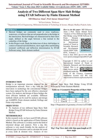
Fig 4 3D View slab with 20m span length at 15◦ skew angle
Results
Figure 5 Maximum Displacement Graph
3. International Journal of Trend in Scientific Research and Development @ www.ijtsrd.com eISSN: 2456-6470
@ IJTSRD | Unique Paper ID – IJTSRD56327 | Volume – 7 | Issue – 3 | May-June 2023 Page 114
Figure 6 Maximum Stress Qx Graph
Figure 7 Maximum Stress Qy Graph
Figure 8 Maximum Bending Moment Mx Graph
4. International Journal of Trend in Scientific Research and Development @ www.ijtsrd.com eISSN: 2456-6470
@ IJTSRD | Unique Paper ID – IJTSRD56327 | Volume – 7 | Issue – 3 | May-June 2023 Page 115
Figure 9 Maximum Bending Moment My Graph
Figure 10 Maximum Bending Moment Mz Graph
CONCLUSION
When span is increases than Max Bending Moment in
X Direction ( in KNm/m) of Skew Slab Bridge is
decreases from 61.9940 to 60.6140 and Max Bending
Moment in Y Direction ( in KNm/m) of Skew Slab
Bridge Decreases 53.916 to 47.890 and Max Bending
Moment in Z Direction ( in KNm/m) of Skew Slab
Bridge Decreases 52.07 to 43.6748. Hence higher
span of bridge is considered.
REFERENCES
[1] Heins, C.l P.l and Lawrie, R.l A.: Design of
Modern Concrete Highway Bridges, Wiley
Inter-science Publication, New York, 1984,
PP.l 203-204.
[2] J. Chajes “Load Distribution For A Highly
Skewed Bridge: Testing And Analysis”,
Journal Of Bridge Engineering, Vol. 9, No. 6,
November 2004
[3] Jaeger, L.l G., and Bakht, B., The Grillage
Analogy in Bridge Analysis, Canadian Journal
of Civil.
[4] M. G. Kalyanshetti and R. P. Shriram (2013)
Effectiveness of Courbon’s theory in the
analysis of T-beam bridge.
[5] Mahmad saber (2015) “Comparison design
result Of RCC building using Stand and Etabs
Software” Volume 2 (IJIRAE).
[6] Mohan Lal, Vedpal (2016) “Study of skewness
angle in reinforced concrete girder bridges”
Volume 2 IJNTR. Vikash Khatri, P. R. Maiti
(2012) ”Analysis of skew bridges using
computational method” Volume 2 IJCER.
[7] Mohan Lal, Vedpal (2016) “Study of skewness
angle in reinforced concrete girder bridges”
Volume 2 IJNTR. Vikash Khatri, P. R. Maiti
(2012) ”Analysis of skew bridges using
computational method” Volume 2 IJCER.
[8] Muthu, K. U., Kamaranth, Ibrahim A and
Mattarneh, H., Load deflection behaviour of
partially restrained slab strips. Eng. Struct.,
2007, 29, 663–674.