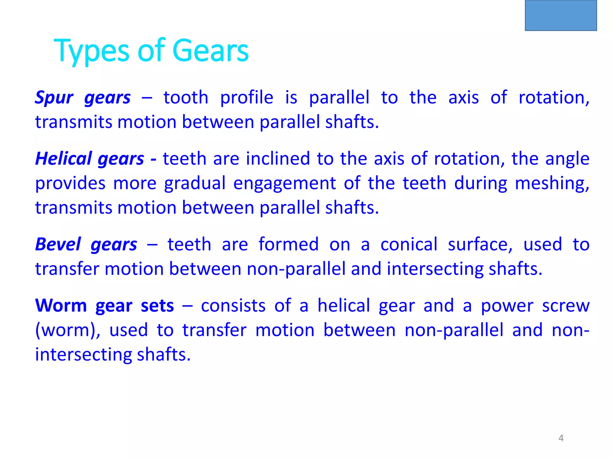
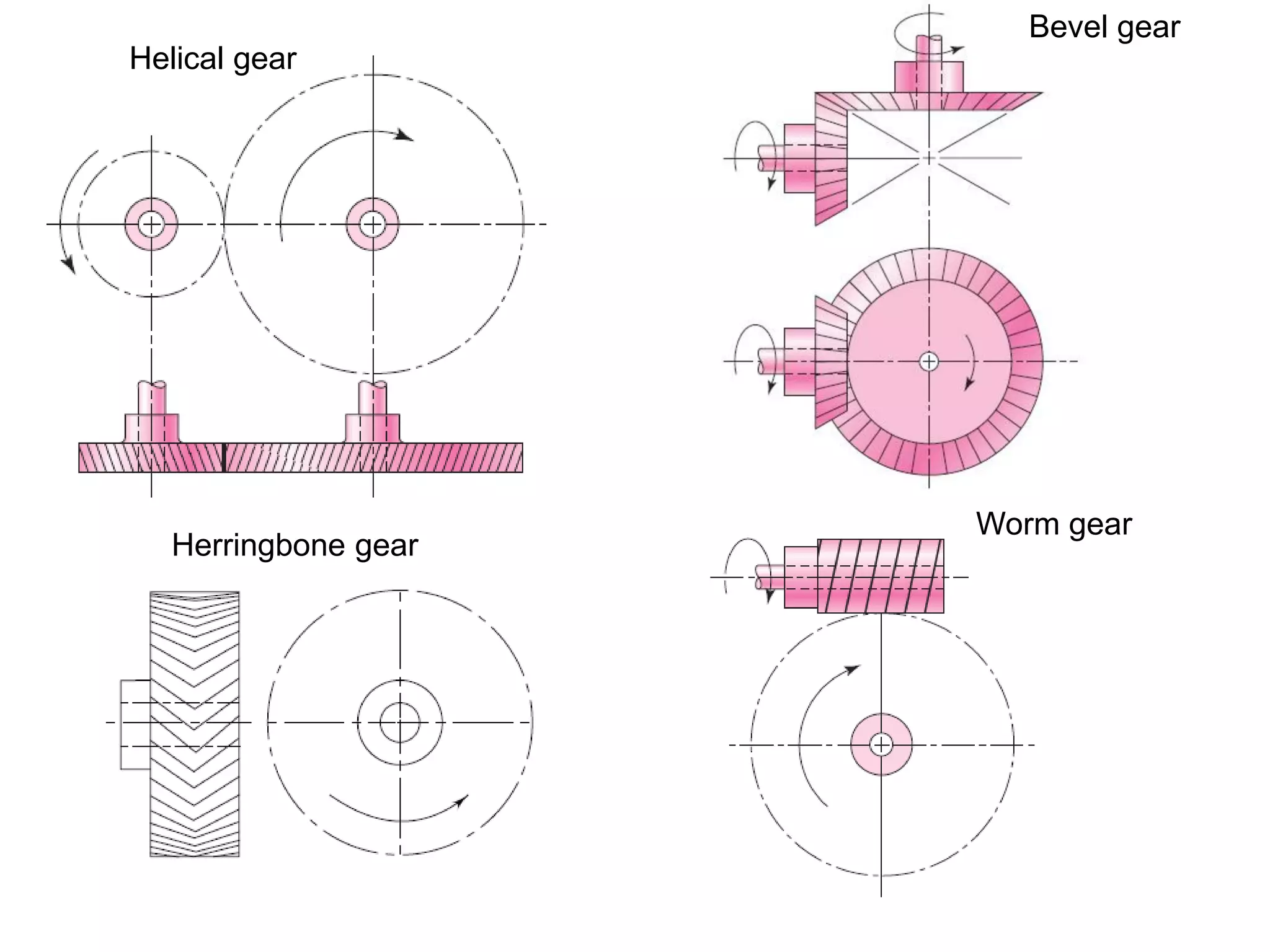
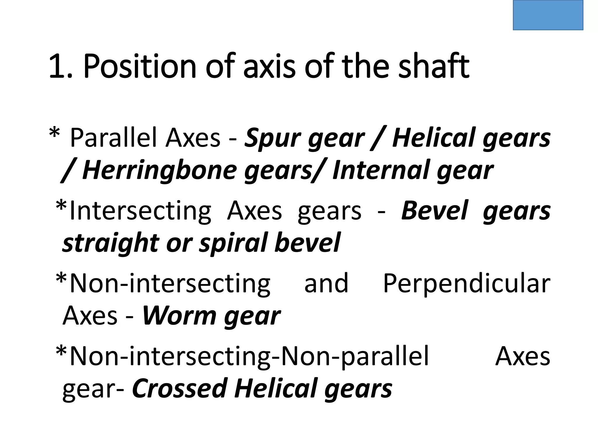
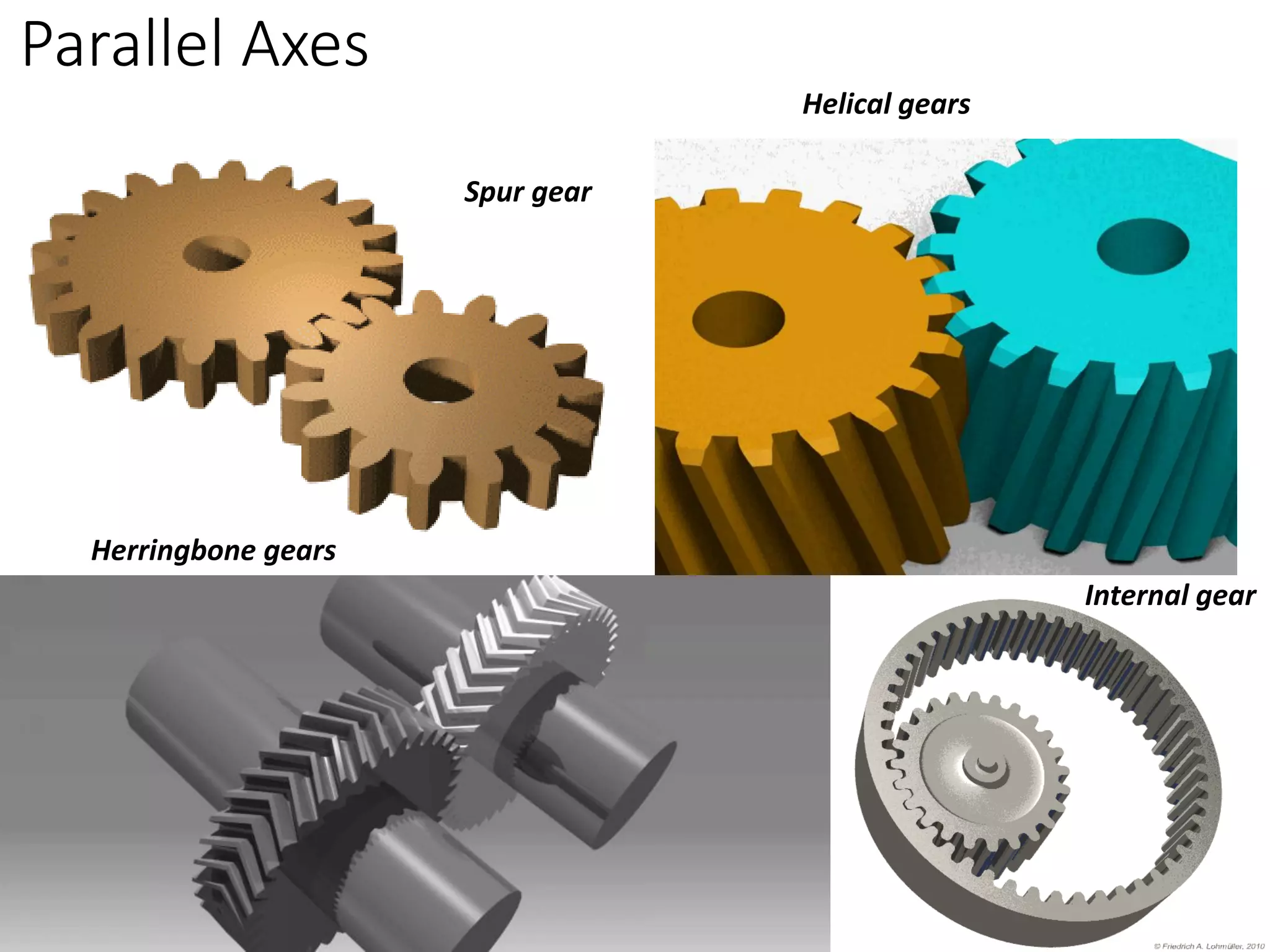
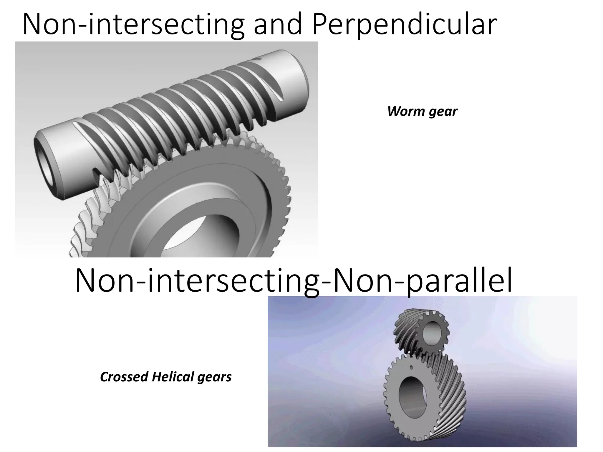
SlideShare a Scribd company logo
Power transmission
Power transmission is the movement of energy from
its place of generation to a location where it
is applied to perform useful work.
Power is defined formally as units of energy per
unit time.
Friction wheels
A gear can be defined as the mechanical element
used for transmitting power by rotary/linear motion from
one shaft to another by means of progressive
engagement of projections called teeth.
3
Gear
Types of Gears
4
Spur gears – tooth profile is parallel to the axis of rotation,
transmits motion between parallel shafts.
Helical gears - teeth are inclined to the axis of rotation, the angle
provides more gradual engagement of the teeth during meshing,
transmits motion between parallel shafts.
Bevel gears – teeth are formed on a conical surface, used to
transfer motion between non-parallel and intersecting shafts.
Worm gear sets – consists of a helical gear and a power screw
(worm), used to transfer motion between non-parallel and non-
intersecting shafts.
Helical gear
Bevel gear
Worm gear
Herringbone gear
Types of Gears
A) Bevel Gear Transmit power at 90o B) The Miter gear C)
Angular bevel gears D) Hypoid Gears
Worm gear
Rack and Pinion
Herringbone gear
Advantages of Gear drives
a) Compact as compared to belt or chain.
b) Transmit higher power and speed as
compare to belt or chain.
c) Transmit power between shafts which
are parallel / non-parallel, intersecting /
non-intersecting.
d ) Used for wide range of speed ratios.
e ) Gear drives are positive drives.
9
Classifications of Gears
1. Position of axis of the shaft.
2. Peripheral velocity of the gears
3. Type of gearing
4. Position of teeth on the gear
surface
10
1. Position of axis of the shaft
* Parallel Axes - Spur gear / Helical gears
/ Herringbone gears/ Internal gear
*Intersecting Axes gears - Bevel gears
straight or spiral bevel
*Non-intersecting and Perpendicular
Axes - Worm gear
*Non-intersecting-Non-parallel Axes
gear- Crossed Helical gears
Parallel Axes
Spur gear
Helical gears
Herringbone gears
Internal gear
Intersecting Axes gears
Straight Bevel gears
Spiral bevel
Non-intersecting and Perpendicular
Worm gear
Non-intersecting-Non-parallel
Crossed Helical gears
2. Peripheral velocity of the gears
• Low velocity
❖ less than 3 m/s
• Medium velocity
❖From 3 m/s to 15 m/s
• High velocity
❖ more than 15 m/s
3. Type of gearing
• External gearing
Gear and pinion
• Internal gear
Annular wheel and pinion
• Rack and pinion
16
4. Position of teeth on the gear surface
• Straight teeth
• Inclined teeth
• Curved teeth
17
Limitations of gear drives
a) Gear drives are costlier than belt or chain drives.
b) Require continuous lubrication and precise alignment.
c) Can not be used for transmitting power over very long distance.
18
• Toys and Small Mechanisms – small, low load, low cost >>>>>>
kinematic analysis.
• Appliance gears – long life, low noise & cost low to moderate
load >>>>>> kinematic & some stress analysis.
• Power transmission – long life, high load and speed >>>>>>
kinematic & stress analysis.
• Aerospace gears – light weight, moderate to high load >>>>>>
kinematic & stress analysis.
• Control gears – long life, low noise, precision gears >>>>>>
kinematic & stress analysis.
Applications of Gears
Gear Terminology
• Top Land It is the top surface of the tooth.
• Face It is the surface of the gear above the pitch circle .
• Flank It is the surface of the gear below the pitch circle .
19
Gear Terminology
Pitch Circle : It is an imaginary circle which by pure rolling
action would transmit same motion as the actual gear.
Pitch Circle Diameter(d) : It is diameter of pitch circle.
Circular Pitch : It is the distance measured along the
circumference of the pitch circle ,from point on one tooth to
corresponding point on next tooth.
20
Gear Terminology
• Addendum - It is radial distance between top land of the teeth
and pitch circle. Normally addendum = 1 module.
• Dedendum - It is radial distance between bottom land of the
teeth and pitch circle.
• Total/whole depth : It is radial distance between Addendum
circle and dedendum circle or sum of Addendum and
dedendum.
21
Gear Terminology
• Tooth Thickness : It is width of tooth measured along pitch
circle.
• Face width : It is length of gear tooth measured along line
parallel to gear axes.
• Base/clearance Circle : It is the circle on which the involute
profile of the gear tooth is generated.
22
Gear Terminology
• Root/Dedendum diameter : It is diameter of base of tooth
space.
• Outside diameter : It is diameter of Addendum circle.
• Fillet radius : The curved surface of the tooth flank joining it to
bottom land.
• Speed ratio : It is ratio of pinion speed to gear speed.
23
Gear Terminology
• Clearance Distance between the root circle of a gear and the
addendum circle of its mate.
• Working depth Depth of engagement of two gears, that is, the
sum of their operating addendums.
• Base pitch, normal pitch, In involute gears, distance from one
face of a tooth to the corresponding face of an adjacent tooth
on the same gear, measured along the base circle.
24
Gear Terminology
Gear Terminology formula
Diametral pitch (Pd): The number of teeth of a gear unit pitch diameter (number
of teeth divided by the pitch diameter).
Where
Pd = diametral pitch
T= number of teeth
d= pitch diameter
Module (m): Pitch diameter divided by number of teeth.
(Pitch diameter is usually specified in inches or millimeters)
• Module is the inverse of diametral pitch.
m = d/T
Contact ratio can be visualized as the average number of tooth pairs in contact
during mesh.
This means more contact ratio, smoother will be the operation.
d
T
Pd =
Gear Terminology Formula
Backlash-It is the difference between the tooth space b/w the
tooth space and tooth thickness as measured along pitch
circle.
Backlash allows room for an oil film under all conditions
of thermal expansion or contraction and is influenced by
deviation of center distance, tooth thickness, pitch, profile
and lead errors.
Gear Terminology
Nomenclature
Smaller Gear is Pinion and Larger one is the gear
In most application the pinion is the driver, This reduces speed
but it increases torque.
Comparative Gear Tooth sizes 4 to 16DP
STD Tooth System
Pressure angle
Pitch
line
Line of centers
Base
circle
Base
circle
Pitch
circle
Pitch
circle
Pressure angle φ
Standard pressure angles, 14.5o
(old), 20o
, and 25o
It is the angle between the line of action and a line tangent to the 2 pitch circle at the
pitch point
Law of Gearing
2
1
D
C
n
n
ω1
ω2
A
B
t
P
Vc
Vd
To maintain this constant angular velocity ratio between two meshing gears, the
common normal (n-n in the figure) of the tooth profiles, at all contact points with
in mesh, should always pass through a fixed point (P in the figure)
Law of gearing
ab-line of action
c-common point
P-pitch point
rA- pitch radius
Law of Gearing
The common normal at the point of contact between a pair of
teeth must always pass through the pitch point.
The angular velocity ratio between the gears of a gear set must
remain constant throughout the mesh.
Velocity ratio VR= angular velocity of follower/angular velocity of
driver
w2/w1=N2/N1=d1/d2=r1/r2=T1/T2
Gear ratio G=T/t = no of teeth on the gear or wheel/no of teeth on
pinion
O1 and O2 centres of the two gears rotating with angular velocities w1 and w2 respectively
C is the point of contact between the teeth of the two gears and NN is the common normal at
the point of contact.
is the velocity of the point C, (gear 1), is the velocity of the point C, (gear 2)
Circles
Base circle radius
rB=r cos φ
r-pitch circle radius
Forms of Teeth
1. Cycloidal teeth ; and
2. Involute teeth.
Cycloidal tooth profile
NO INTERFERENCE
Generation of In volute
➢Pressure angle remains same throughout the operation.
➢Teeths are weaker.
➢It is easier to manufacture due to convex surface.
➢The velocity is not affected due to variation in centre
distance.
➢Interference takes place.
➢More wear and tear as contact takes place between
convex surfaces.
➢Pressure angle keeps on changing during the
operation. The angle is maximum at the start and end
of engagement. It is zero at pitch point.
➢Teeths are stronger.
➢It is difficult to manufacture due to requirement of
hypocycloid and epicycloids..
➢The centre distance should remains the same.
➢There is no interference.
➢Less wear and tear as concave flank makes contact
with convex flank.
Involute profile
Cycloid profile
Comparison Between Involute and Cycloidal Gears
Advantages of involute gears
1. The centre distance for a pair of involute gears can be
varied within limits without changing the velocity ratio.
(cycloidal gears which requires exact centre distance to
be maintained.)
2. In involute gears, the pressure angle, from the start of
the engagement of teeth to the end of the engagement,
remains constant. It is necessary for smooth running and
less wear of gears.
3. The face and flank of involute teeth are generated by a
single curve where as in cycloidal gears, double curves
(i.e. epi-cycloid and hypo-cycloid) are required for the face
and flank respectively. (involute teeth are easy to
manufacture than cycloidal teeth.)
Comparison Between Involute and Cycloidal Gears
Advantages of Cycloidal gears
1. Since the cycloidal teeth have wider flanks, therefore the
cycloidal gears are stronger than the involute gears, for the
same pitch. (Cycloidal teeth are preferred specially for cast
teeth.)
2. In cycloidal gears, the contact takes place between a
convex flank and concave surface, whereas in involute gears,
the convex surfaces are in contact. This condition results in less
wear in cycloidal gears as compared to involute gears.
However the difference in wear is negligible.
3. In cycloidal gears, the interference does not occur at all.
Though there are advantages of cycloidal gears but they are
outweighed by the greater simplicity and flexibility of the
involute gears.
INTERFERENCE
Interference
Avoiding Interference
• Increase the pressure angle- reduce the base circle-reduce not involute
portion
• Increase the addendum of Pinion reduce addendum of gear
• Use minimum no of teeth
Undercutting
GEAR TRAINS
• A gear train is two or more gear working together by meshing their teeth and
turning each other in a system to generate power and speed
• It reduces speed and increases torque
• Electric motors are used with the gear systems to reduce the speed and
increase the torque
• Simple gear train
• Compound gear train
• Reverted gear train
• EPI-CYCLIC gear
train
Types of Gear Trains
Simple Gear Train
The most common of the gear train is the gear pair
connecting parallel shafts. The teeth of this type can be
spur, helical or herringbone.
Compound Gear Train
For large velocities, compound arrangement is
preferred and two or more gears may rotate about a
single axis
Reverted gear train
When the axes of the first gear and the last gear are
co-axial, then the gear train is known as reverted gear
train
Spur gear generation pinion cutter
Worm gear generation by Gear Hobbing
Gear Tooth Forces
(i) It is assumed that the pinion is the driving
element while gear is the driven element.
(ii) It is assumed that the pinion rotates in
anticlockwise direction. Therefore, the gear
will rotate in clockwise direction.
(iii) In running condition, the point 2 on the
pinion and the point 1 on gear are in contact
with each other.
(i) The gear G is the driven element. It is made
to rotate in clockwise direction. Therefore, at
point 1 on the gear G, the tangential
component Pt will act towards the left.
(ii) There will be equal and opposite reaction
at point 2 on the pinion P. It is observed that
the direction of tangential component Pt on the
driving element, that is, pinion is opposite to
the direction of rotation.
The radial component acts towards the centre of the respective gear.
In order to avoid the breakage of gear tooth due to
bending, the beam strength should be more than the
effective force between the meshing teeth.
Y is called the Lewis form factor
Beam strength (Sb) is the maximum value of the
tangential force that the tooth can transmit without
bending failure.
In gear design, the maximum force (due to maximum torque) is the criterion. This is
accounted by means of a service factor Cs.
There are two methods to account for the dynamic load—approximate estimation by
the velocity factor in the preliminary stages of gear design and precise calculation by
Buckingham’s equation in the final stages of gear design.
Velocity factor Cv developed by Barth is used.
In the final stages of gear design, when gear dimensions are known, errors specified
and the quality of gears determined, the dynamic load is calculated by equations
derived by Earle Buckingham. The effective load is given by,
The effective load between two meshing teeth is given by,
Gears of Grade 11 and Grade 12 are
manufactured by casting. Gears of Grade
8 and Grade 9 require rough and fi ne
hobbing. Gears of Grade 6 are obtained
by hobbing and rough grinding, while
Grade 4 requires shaving and finish
grinding.
Method of manufacture for gears
depends upon the grade of the
gear
In order to avoid failure of gear
tooth due to bending,
Buckingham’s equation is based on Hertz theory of contact stresses. When two
cylinders are pressed together as shown in Fig., the contact stress is given by,
Due to deformation under the action
of load P, a rectangular surface of
width (2b) and length (l) is formed
between the two cylinders. The
elliptical stress distribution across the
width (2b)
PN
Pt
Figure shows the contact between two
meshing teeth at the pitch point. The radii
r1 and r2 in Eq. (d) are to be replaced by
the radii of curvature at the pitch point.
The wear on the gear tooth generally occurs at or near the pitch line
Therefore, the wear strength is the maximum value of the tangential force
that the tooth can transmit without pitting failure.
Equation is known as Buckingham’s equation for wear.
When the tangential force is increased, the contact stress also increases. Pitting
occurs when the contact stress reaches the magnitude of the surface endurance
strength.
The ratio factor for internal gears
The expression for the load-stress factor K can be simplified when both the
gears are made of steel with a 20° pressure angle.
The above equation is applicable only when both the gears are made of steel with
a 20° pressure angle.
The gear material should have sufficient strength to resist failure due to
breakage of the tooth. The gear material should have sufficient surface
endurance strength to avoid failure due to destructive pitting.
1. Corrosive wear
2. Abrasive wear
3. Initial Pitting The initial or corrective pitting is a localized phenomenon,
characterized by small pits at high spots. Such high spots are progressively
worn out and the load is redistributed. Initial pitting is caused by the errors in
tooth profile, surface irregularities and misalignment.
4. Destructive Pitting Destructive pitting is a surface fatigue failure, which
occurs when the load on the gear tooth exceeds the surface endurance
strength of the material. This type of failure is characterized by pits, which
continue to grow resulting in complete destruction of the tooth surface and,
in some cases, even premature breakage of the tooth.
5. Scoring Excessive surface pressure, high surface speed and inadequate supply
of lubricant result in the breakdown of the oil film. This results in excessive
frictional heat and overheating of the meshing teeth. Scoring is a stick-slip
phenomenon, in which alternate welding and shearing takes place rapidly at
the high spots.
Gear Failure
design of  Spur gear

More Related Content

What's hot

Spur gear and design of spur gear
Spur gear and design of spur gearSpur gear and design of spur gear
Spur gear and design of spur gear
Yash Shah
 
Gear trains
Gear trainsGear trains
Design and Drawing of CAM profiles
Design and Drawing of CAM profilesDesign and Drawing of CAM profiles
2 self energizing brakes
2 self energizing brakes2 self energizing brakes
2 self energizing brakes
shaikusmanshag
 
Spur gear and helical gear
Spur gear and helical gearSpur gear and helical gear
Spur gear and helical gear
Vishvak Vashi
 
1.6 interference in gears
1.6 interference in gears1.6 interference in gears
1.6 interference in gears
Kiran Wakchaure
 
Worm gear
Worm gearWorm gear
Worm gear
balram yadav
 
Kinematics of machine (Tooth Profiles of Gears)
Kinematics of machine (Tooth Profiles of Gears)Kinematics of machine (Tooth Profiles of Gears)
Kinematics of machine (Tooth Profiles of Gears)
Graphic Era University.
 
Flywheel and Governors
Flywheel and GovernorsFlywheel and Governors
Flywheel and Governors
Bhosalesarkar
 
Location and locating devices used in jigs and fixtures
Location and locating devices used in jigs and fixturesLocation and locating devices used in jigs and fixtures
Location and locating devices used in jigs and fixtures
Amruta Rane
 
Gear
GearGear
Module 4 gears
Module 4 gearsModule 4 gears
Module 4 gears
taruian
 
Spur gears
Spur gearsSpur gears
Chain drive system
Chain drive systemChain drive system
Chain drive system
Bhagyashri Dhage
 
Study of Gear Technology
Study of Gear TechnologyStudy of Gear Technology
Study of Gear Technology
Sarath Chandra
 
Basics of Gear
Basics of GearBasics of Gear
Basics of Gear
Gujrathi Sonam
 
Spur gear
Spur gearSpur gear
Spur gear
Muddassar Awan
 
Types of Axles
Types of AxlesTypes of Axles
Types of Axles
Sumati Saxena
 

What's hot (20)

Spur gear and design of spur gear
Spur gear and design of spur gearSpur gear and design of spur gear
Spur gear and design of spur gear
 
Gear trains
Gear trainsGear trains
Gear trains
 
Design and Drawing of CAM profiles
Design and Drawing of CAM profilesDesign and Drawing of CAM profiles
Design and Drawing of CAM profiles
 
2 self energizing brakes
2 self energizing brakes2 self energizing brakes
2 self energizing brakes
 
Spur gear and helical gear
Spur gear and helical gearSpur gear and helical gear
Spur gear and helical gear
 
1.6 interference in gears
1.6 interference in gears1.6 interference in gears
1.6 interference in gears
 
Worm gear
Worm gearWorm gear
Worm gear
 
Kinematics of machine (Tooth Profiles of Gears)
Kinematics of machine (Tooth Profiles of Gears)Kinematics of machine (Tooth Profiles of Gears)
Kinematics of machine (Tooth Profiles of Gears)
 
Flywheel and Governors
Flywheel and GovernorsFlywheel and Governors
Flywheel and Governors
 
Location and locating devices used in jigs and fixtures
Location and locating devices used in jigs and fixturesLocation and locating devices used in jigs and fixtures
Location and locating devices used in jigs and fixtures
 
Gear
GearGear
Gear
 
Module 4 gears
Module 4 gearsModule 4 gears
Module 4 gears
 
Spur gears
Spur gearsSpur gears
Spur gears
 
Chain drive system
Chain drive systemChain drive system
Chain drive system
 
Study of Gear Technology
Study of Gear TechnologyStudy of Gear Technology
Study of Gear Technology
 
Bearing
BearingBearing
Bearing
 
Basics of Gear
Basics of GearBasics of Gear
Basics of Gear
 
Spur gear
Spur gearSpur gear
Spur gear
 
Gear train
Gear trainGear train
Gear train
 
Types of Axles
Types of AxlesTypes of Axles
Types of Axles
 

Similar to design of Spur gear

Helical and spur gears.pptx
Helical and spur gears.pptxHelical and spur gears.pptx
Helical and spur gears.pptx
MohsinIftikharLabEng
 
spur gear.pptx, type of gear and design of gear
spur gear.pptx, type of gear and design of gearspur gear.pptx, type of gear and design of gear
spur gear.pptx, type of gear and design of gear
haymanot16
 
differntial gear.pdf
differntial gear.pdfdifferntial gear.pdf
differntial gear.pdf
shinojmc
 
Gears
GearsGears
Gear
GearGear
Gear manufacturing by Engr Rehan Zeb Khan PMAS AAUR
Gear manufacturing  by Engr Rehan Zeb Khan PMAS AAURGear manufacturing  by Engr Rehan Zeb Khan PMAS AAUR
Gear manufacturing by Engr Rehan Zeb Khan PMAS AAUR
PMAS-Arid Agriculture Universty Rawalpindi
 
Spur gears and its manufacturing processes
 Spur gears and its manufacturing processes Spur gears and its manufacturing processes
Spur gears and its manufacturing processes
YashChanne2
 
Lecture 2 spur gear
Lecture 2 spur gearLecture 2 spur gear
Lecture 2 spur gear
GaneshFodase1
 
Introduction to gears
Introduction to gearsIntroduction to gears
Introduction to gears
Naseel Ibnu Azeez
 
Gear
GearGear
Design of gears by aliyi umer
Design of gears by aliyi umerDesign of gears by aliyi umer
Design of gears by aliyi umer
Aliyi Umer
 
3131906_07_Gears_and_Gear_Trains__Lect_1_948.ppt
3131906_07_Gears_and_Gear_Trains__Lect_1_948.ppt3131906_07_Gears_and_Gear_Trains__Lect_1_948.ppt
3131906_07_Gears_and_Gear_Trains__Lect_1_948.ppt
DebabrataMondal42
 
Gears & its Terminology
Gears & its TerminologyGears & its Terminology
Gears & its Terminology
VINOTHRAJA189
 
Elemen Mesin II - Rodagigi Lurus
Elemen Mesin II - Rodagigi LurusElemen Mesin II - Rodagigi Lurus
Elemen Mesin II - Rodagigi Lurus
Charis Muhammad
 
Design of transmission systems by A.Vinoth Jebaraj
Design of transmission systems by A.Vinoth JebarajDesign of transmission systems by A.Vinoth Jebaraj
Design of transmission systems by A.Vinoth Jebaraj
Vinoth Jebaraj A
 
Gear Box Nirjhar
Gear Box NirjharGear Box Nirjhar
Gear Box Nirjhar
Nirjhar Chakravorti
 
Gear_slides.ppt
Gear_slides.pptGear_slides.ppt
Gear_slides.ppt
ME01520Amankumar
 
BME 616 (Machine Design-II) Module 2.pptx
BME 616 (Machine Design-II) Module 2.pptxBME 616 (Machine Design-II) Module 2.pptx
BME 616 (Machine Design-II) Module 2.pptx
SurjeetYadav29
 
About Gears
About Gears About Gears
About Gears
Gaurav Kumar
 

Similar to design of Spur gear (20)

Helical and spur gears.pptx
Helical and spur gears.pptxHelical and spur gears.pptx
Helical and spur gears.pptx
 
spur gear.pptx, type of gear and design of gear
spur gear.pptx, type of gear and design of gearspur gear.pptx, type of gear and design of gear
spur gear.pptx, type of gear and design of gear
 
differntial gear.pdf
differntial gear.pdfdifferntial gear.pdf
differntial gear.pdf
 
Gears
GearsGears
Gears
 
Gear
GearGear
Gear
 
Gear manufacturing by Engr Rehan Zeb Khan PMAS AAUR
Gear manufacturing  by Engr Rehan Zeb Khan PMAS AAURGear manufacturing  by Engr Rehan Zeb Khan PMAS AAUR
Gear manufacturing by Engr Rehan Zeb Khan PMAS AAUR
 
Spur gears and its manufacturing processes
 Spur gears and its manufacturing processes Spur gears and its manufacturing processes
Spur gears and its manufacturing processes
 
Lecture 2 spur gear
Lecture 2 spur gearLecture 2 spur gear
Lecture 2 spur gear
 
Introduction to gears
Introduction to gearsIntroduction to gears
Introduction to gears
 
Gear
GearGear
Gear
 
Design of gears by aliyi umer
Design of gears by aliyi umerDesign of gears by aliyi umer
Design of gears by aliyi umer
 
3131906_07_Gears_and_Gear_Trains__Lect_1_948.ppt
3131906_07_Gears_and_Gear_Trains__Lect_1_948.ppt3131906_07_Gears_and_Gear_Trains__Lect_1_948.ppt
3131906_07_Gears_and_Gear_Trains__Lect_1_948.ppt
 
Gears & its Terminology
Gears & its TerminologyGears & its Terminology
Gears & its Terminology
 
Elemen Mesin II - Rodagigi Lurus
Elemen Mesin II - Rodagigi LurusElemen Mesin II - Rodagigi Lurus
Elemen Mesin II - Rodagigi Lurus
 
Design of transmission systems by A.Vinoth Jebaraj
Design of transmission systems by A.Vinoth JebarajDesign of transmission systems by A.Vinoth Jebaraj
Design of transmission systems by A.Vinoth Jebaraj
 
Gear
GearGear
Gear
 
Gear Box Nirjhar
Gear Box NirjharGear Box Nirjhar
Gear Box Nirjhar
 
Gear_slides.ppt
Gear_slides.pptGear_slides.ppt
Gear_slides.ppt
 
BME 616 (Machine Design-II) Module 2.pptx
BME 616 (Machine Design-II) Module 2.pptxBME 616 (Machine Design-II) Module 2.pptx
BME 616 (Machine Design-II) Module 2.pptx
 
About Gears
About Gears About Gears
About Gears
 

Recently uploaded

2024.06.01 Introducing a competency framework for languag learning materials ...
2024.06.01 Introducing a competency framework for languag learning materials ...2024.06.01 Introducing a competency framework for languag learning materials ...
2024.06.01 Introducing a competency framework for languag learning materials ...
Sandy Millin
 
Mule 4.6 & Java 17 Upgrade | MuleSoft Mysore Meetup #46
Mule 4.6 & Java 17 Upgrade | MuleSoft Mysore Meetup #46Mule 4.6 & Java 17 Upgrade | MuleSoft Mysore Meetup #46
Mule 4.6 & Java 17 Upgrade | MuleSoft Mysore Meetup #46
MysoreMuleSoftMeetup
 
Azure Interview Questions and Answers PDF By ScholarHat
Azure Interview Questions and Answers PDF By ScholarHatAzure Interview Questions and Answers PDF By ScholarHat
Azure Interview Questions and Answers PDF By ScholarHat
Scholarhat
 
How libraries can support authors with open access requirements for UKRI fund...
How libraries can support authors with open access requirements for UKRI fund...How libraries can support authors with open access requirements for UKRI fund...
How libraries can support authors with open access requirements for UKRI fund...
Jisc
 
STRAND 3 HYGIENIC PRACTICES.pptx GRADE 7 CBC
STRAND 3 HYGIENIC PRACTICES.pptx GRADE 7 CBCSTRAND 3 HYGIENIC PRACTICES.pptx GRADE 7 CBC
STRAND 3 HYGIENIC PRACTICES.pptx GRADE 7 CBC
kimdan468
 
Language Across the Curriculm LAC B.Ed.
Language Across the  Curriculm LAC B.Ed.Language Across the  Curriculm LAC B.Ed.
Language Across the Curriculm LAC B.Ed.
Atul Kumar Singh
 
Unit 2- Research Aptitude (UGC NET Paper I).pdf
Unit 2- Research Aptitude (UGC NET Paper I).pdfUnit 2- Research Aptitude (UGC NET Paper I).pdf
Unit 2- Research Aptitude (UGC NET Paper I).pdf
Thiyagu K
 
Guidance_and_Counselling.pdf B.Ed. 4th Semester
Guidance_and_Counselling.pdf B.Ed. 4th SemesterGuidance_and_Counselling.pdf B.Ed. 4th Semester
Guidance_and_Counselling.pdf B.Ed. 4th Semester
Atul Kumar Singh
 
Chapter 3 - Islamic Banking Products and Services.pptx
Chapter 3 - Islamic Banking Products and Services.pptxChapter 3 - Islamic Banking Products and Services.pptx
Chapter 3 - Islamic Banking Products and Services.pptx
Mohd Adib Abd Muin, Senior Lecturer at Universiti Utara Malaysia
 
TESDA TM1 REVIEWER FOR NATIONAL ASSESSMENT WRITTEN AND ORAL QUESTIONS WITH A...
TESDA TM1 REVIEWER  FOR NATIONAL ASSESSMENT WRITTEN AND ORAL QUESTIONS WITH A...TESDA TM1 REVIEWER  FOR NATIONAL ASSESSMENT WRITTEN AND ORAL QUESTIONS WITH A...
TESDA TM1 REVIEWER FOR NATIONAL ASSESSMENT WRITTEN AND ORAL QUESTIONS WITH A...
EugeneSaldivar
 
Multithreading_in_C++ - std::thread, race condition
Multithreading_in_C++ - std::thread, race conditionMultithreading_in_C++ - std::thread, race condition
Multithreading_in_C++ - std::thread, race condition
Mohammed Sikander
 
The basics of sentences session 5pptx.pptx
The basics of sentences session 5pptx.pptxThe basics of sentences session 5pptx.pptx
The basics of sentences session 5pptx.pptx
heathfieldcps1
 
MASS MEDIA STUDIES-835-CLASS XI Resource Material.pdf
MASS MEDIA STUDIES-835-CLASS XI Resource Material.pdfMASS MEDIA STUDIES-835-CLASS XI Resource Material.pdf
MASS MEDIA STUDIES-835-CLASS XI Resource Material.pdf
goswamiyash170123
 
Best Digital Marketing Institute In NOIDA
Best Digital Marketing Institute In NOIDABest Digital Marketing Institute In NOIDA
Best Digital Marketing Institute In NOIDA
deeptiverma2406
 
The Challenger.pdf DNHS Official Publication
The Challenger.pdf DNHS Official PublicationThe Challenger.pdf DNHS Official Publication
The Challenger.pdf DNHS Official Publication
Delapenabediema
 
Unit 8 - Information and Communication Technology (Paper I).pdf
Unit 8 - Information and Communication Technology (Paper I).pdfUnit 8 - Information and Communication Technology (Paper I).pdf
Unit 8 - Information and Communication Technology (Paper I).pdf
Thiyagu K
 
Exploiting Artificial Intelligence for Empowering Researchers and Faculty, In...
Exploiting Artificial Intelligence for Empowering Researchers and Faculty, In...Exploiting Artificial Intelligence for Empowering Researchers and Faculty, In...
Exploiting Artificial Intelligence for Empowering Researchers and Faculty, In...
Dr. Vinod Kumar Kanvaria
 
Normal Labour/ Stages of Labour/ Mechanism of Labour
Normal Labour/ Stages of Labour/ Mechanism of LabourNormal Labour/ Stages of Labour/ Mechanism of Labour
Normal Labour/ Stages of Labour/ Mechanism of Labour
Wasim Ak
 
1.4 modern child centered education - mahatma gandhi-2.pptx
1.4 modern child centered education - mahatma gandhi-2.pptx1.4 modern child centered education - mahatma gandhi-2.pptx
1.4 modern child centered education - mahatma gandhi-2.pptx
JosvitaDsouza2
 
BÀI TẬP BỔ TRỢ TIẾNG ANH GLOBAL SUCCESS LỚP 3 - CẢ NĂM (CÓ FILE NGHE VÀ ĐÁP Á...
BÀI TẬP BỔ TRỢ TIẾNG ANH GLOBAL SUCCESS LỚP 3 - CẢ NĂM (CÓ FILE NGHE VÀ ĐÁP Á...BÀI TẬP BỔ TRỢ TIẾNG ANH GLOBAL SUCCESS LỚP 3 - CẢ NĂM (CÓ FILE NGHE VÀ ĐÁP Á...
BÀI TẬP BỔ TRỢ TIẾNG ANH GLOBAL SUCCESS LỚP 3 - CẢ NĂM (CÓ FILE NGHE VÀ ĐÁP Á...
Nguyen Thanh Tu Collection
 

Recently uploaded (20)

2024.06.01 Introducing a competency framework for languag learning materials ...
2024.06.01 Introducing a competency framework for languag learning materials ...2024.06.01 Introducing a competency framework for languag learning materials ...
2024.06.01 Introducing a competency framework for languag learning materials ...
 
Mule 4.6 & Java 17 Upgrade | MuleSoft Mysore Meetup #46
Mule 4.6 & Java 17 Upgrade | MuleSoft Mysore Meetup #46Mule 4.6 & Java 17 Upgrade | MuleSoft Mysore Meetup #46
Mule 4.6 & Java 17 Upgrade | MuleSoft Mysore Meetup #46
 
Azure Interview Questions and Answers PDF By ScholarHat
Azure Interview Questions and Answers PDF By ScholarHatAzure Interview Questions and Answers PDF By ScholarHat
Azure Interview Questions and Answers PDF By ScholarHat
 
How libraries can support authors with open access requirements for UKRI fund...
How libraries can support authors with open access requirements for UKRI fund...How libraries can support authors with open access requirements for UKRI fund...
How libraries can support authors with open access requirements for UKRI fund...
 
STRAND 3 HYGIENIC PRACTICES.pptx GRADE 7 CBC
STRAND 3 HYGIENIC PRACTICES.pptx GRADE 7 CBCSTRAND 3 HYGIENIC PRACTICES.pptx GRADE 7 CBC
STRAND 3 HYGIENIC PRACTICES.pptx GRADE 7 CBC
 
Language Across the Curriculm LAC B.Ed.
Language Across the  Curriculm LAC B.Ed.Language Across the  Curriculm LAC B.Ed.
Language Across the Curriculm LAC B.Ed.
 
Unit 2- Research Aptitude (UGC NET Paper I).pdf
Unit 2- Research Aptitude (UGC NET Paper I).pdfUnit 2- Research Aptitude (UGC NET Paper I).pdf
Unit 2- Research Aptitude (UGC NET Paper I).pdf
 
Guidance_and_Counselling.pdf B.Ed. 4th Semester
Guidance_and_Counselling.pdf B.Ed. 4th SemesterGuidance_and_Counselling.pdf B.Ed. 4th Semester
Guidance_and_Counselling.pdf B.Ed. 4th Semester
 
Chapter 3 - Islamic Banking Products and Services.pptx
Chapter 3 - Islamic Banking Products and Services.pptxChapter 3 - Islamic Banking Products and Services.pptx
Chapter 3 - Islamic Banking Products and Services.pptx
 
TESDA TM1 REVIEWER FOR NATIONAL ASSESSMENT WRITTEN AND ORAL QUESTIONS WITH A...
TESDA TM1 REVIEWER  FOR NATIONAL ASSESSMENT WRITTEN AND ORAL QUESTIONS WITH A...TESDA TM1 REVIEWER  FOR NATIONAL ASSESSMENT WRITTEN AND ORAL QUESTIONS WITH A...
TESDA TM1 REVIEWER FOR NATIONAL ASSESSMENT WRITTEN AND ORAL QUESTIONS WITH A...
 
Multithreading_in_C++ - std::thread, race condition
Multithreading_in_C++ - std::thread, race conditionMultithreading_in_C++ - std::thread, race condition
Multithreading_in_C++ - std::thread, race condition
 
The basics of sentences session 5pptx.pptx
The basics of sentences session 5pptx.pptxThe basics of sentences session 5pptx.pptx
The basics of sentences session 5pptx.pptx
 
MASS MEDIA STUDIES-835-CLASS XI Resource Material.pdf
MASS MEDIA STUDIES-835-CLASS XI Resource Material.pdfMASS MEDIA STUDIES-835-CLASS XI Resource Material.pdf
MASS MEDIA STUDIES-835-CLASS XI Resource Material.pdf
 
Best Digital Marketing Institute In NOIDA
Best Digital Marketing Institute In NOIDABest Digital Marketing Institute In NOIDA
Best Digital Marketing Institute In NOIDA
 
The Challenger.pdf DNHS Official Publication
The Challenger.pdf DNHS Official PublicationThe Challenger.pdf DNHS Official Publication
The Challenger.pdf DNHS Official Publication
 
Unit 8 - Information and Communication Technology (Paper I).pdf
Unit 8 - Information and Communication Technology (Paper I).pdfUnit 8 - Information and Communication Technology (Paper I).pdf
Unit 8 - Information and Communication Technology (Paper I).pdf
 
Exploiting Artificial Intelligence for Empowering Researchers and Faculty, In...
Exploiting Artificial Intelligence for Empowering Researchers and Faculty, In...Exploiting Artificial Intelligence for Empowering Researchers and Faculty, In...
Exploiting Artificial Intelligence for Empowering Researchers and Faculty, In...
 
Normal Labour/ Stages of Labour/ Mechanism of Labour
Normal Labour/ Stages of Labour/ Mechanism of LabourNormal Labour/ Stages of Labour/ Mechanism of Labour
Normal Labour/ Stages of Labour/ Mechanism of Labour
 
1.4 modern child centered education - mahatma gandhi-2.pptx
1.4 modern child centered education - mahatma gandhi-2.pptx1.4 modern child centered education - mahatma gandhi-2.pptx
1.4 modern child centered education - mahatma gandhi-2.pptx
 
BÀI TẬP BỔ TRỢ TIẾNG ANH GLOBAL SUCCESS LỚP 3 - CẢ NĂM (CÓ FILE NGHE VÀ ĐÁP Á...
BÀI TẬP BỔ TRỢ TIẾNG ANH GLOBAL SUCCESS LỚP 3 - CẢ NĂM (CÓ FILE NGHE VÀ ĐÁP Á...BÀI TẬP BỔ TRỢ TIẾNG ANH GLOBAL SUCCESS LỚP 3 - CẢ NĂM (CÓ FILE NGHE VÀ ĐÁP Á...
BÀI TẬP BỔ TRỢ TIẾNG ANH GLOBAL SUCCESS LỚP 3 - CẢ NĂM (CÓ FILE NGHE VÀ ĐÁP Á...
 

design of Spur gear

  • 1. Power transmission Power transmission is the movement of energy from its place of generation to a location where it is applied to perform useful work. Power is defined formally as units of energy per unit time.
  • 3. A gear can be defined as the mechanical element used for transmitting power by rotary/linear motion from one shaft to another by means of progressive engagement of projections called teeth. 3 Gear
  • 4. Types of Gears 4 Spur gears – tooth profile is parallel to the axis of rotation, transmits motion between parallel shafts. Helical gears - teeth are inclined to the axis of rotation, the angle provides more gradual engagement of the teeth during meshing, transmits motion between parallel shafts. Bevel gears – teeth are formed on a conical surface, used to transfer motion between non-parallel and intersecting shafts. Worm gear sets – consists of a helical gear and a power screw (worm), used to transfer motion between non-parallel and non- intersecting shafts.
  • 5.
  • 6. Helical gear Bevel gear Worm gear Herringbone gear
  • 8. A) Bevel Gear Transmit power at 90o B) The Miter gear C) Angular bevel gears D) Hypoid Gears Worm gear Rack and Pinion Herringbone gear
  • 9. Advantages of Gear drives a) Compact as compared to belt or chain. b) Transmit higher power and speed as compare to belt or chain. c) Transmit power between shafts which are parallel / non-parallel, intersecting / non-intersecting. d ) Used for wide range of speed ratios. e ) Gear drives are positive drives. 9
  • 10. Classifications of Gears 1. Position of axis of the shaft. 2. Peripheral velocity of the gears 3. Type of gearing 4. Position of teeth on the gear surface 10
  • 11. 1. Position of axis of the shaft * Parallel Axes - Spur gear / Helical gears / Herringbone gears/ Internal gear *Intersecting Axes gears - Bevel gears straight or spiral bevel *Non-intersecting and Perpendicular Axes - Worm gear *Non-intersecting-Non-parallel Axes gear- Crossed Helical gears
  • 12. Parallel Axes Spur gear Helical gears Herringbone gears Internal gear
  • 13. Intersecting Axes gears Straight Bevel gears Spiral bevel
  • 14. Non-intersecting and Perpendicular Worm gear Non-intersecting-Non-parallel Crossed Helical gears
  • 15. 2. Peripheral velocity of the gears • Low velocity ❖ less than 3 m/s • Medium velocity ❖From 3 m/s to 15 m/s • High velocity ❖ more than 15 m/s
  • 16. 3. Type of gearing • External gearing Gear and pinion • Internal gear Annular wheel and pinion • Rack and pinion 16
  • 17. 4. Position of teeth on the gear surface • Straight teeth • Inclined teeth • Curved teeth 17
  • 18. Limitations of gear drives a) Gear drives are costlier than belt or chain drives. b) Require continuous lubrication and precise alignment. c) Can not be used for transmitting power over very long distance. 18 • Toys and Small Mechanisms – small, low load, low cost >>>>>> kinematic analysis. • Appliance gears – long life, low noise & cost low to moderate load >>>>>> kinematic & some stress analysis. • Power transmission – long life, high load and speed >>>>>> kinematic & stress analysis. • Aerospace gears – light weight, moderate to high load >>>>>> kinematic & stress analysis. • Control gears – long life, low noise, precision gears >>>>>> kinematic & stress analysis. Applications of Gears
  • 19. Gear Terminology • Top Land It is the top surface of the tooth. • Face It is the surface of the gear above the pitch circle . • Flank It is the surface of the gear below the pitch circle . 19
  • 20. Gear Terminology Pitch Circle : It is an imaginary circle which by pure rolling action would transmit same motion as the actual gear. Pitch Circle Diameter(d) : It is diameter of pitch circle. Circular Pitch : It is the distance measured along the circumference of the pitch circle ,from point on one tooth to corresponding point on next tooth. 20
  • 21. Gear Terminology • Addendum - It is radial distance between top land of the teeth and pitch circle. Normally addendum = 1 module. • Dedendum - It is radial distance between bottom land of the teeth and pitch circle. • Total/whole depth : It is radial distance between Addendum circle and dedendum circle or sum of Addendum and dedendum. 21
  • 22. Gear Terminology • Tooth Thickness : It is width of tooth measured along pitch circle. • Face width : It is length of gear tooth measured along line parallel to gear axes. • Base/clearance Circle : It is the circle on which the involute profile of the gear tooth is generated. 22
  • 23. Gear Terminology • Root/Dedendum diameter : It is diameter of base of tooth space. • Outside diameter : It is diameter of Addendum circle. • Fillet radius : The curved surface of the tooth flank joining it to bottom land. • Speed ratio : It is ratio of pinion speed to gear speed. 23
  • 24. Gear Terminology • Clearance Distance between the root circle of a gear and the addendum circle of its mate. • Working depth Depth of engagement of two gears, that is, the sum of their operating addendums. • Base pitch, normal pitch, In involute gears, distance from one face of a tooth to the corresponding face of an adjacent tooth on the same gear, measured along the base circle. 24
  • 27. Diametral pitch (Pd): The number of teeth of a gear unit pitch diameter (number of teeth divided by the pitch diameter). Where Pd = diametral pitch T= number of teeth d= pitch diameter Module (m): Pitch diameter divided by number of teeth. (Pitch diameter is usually specified in inches or millimeters) • Module is the inverse of diametral pitch. m = d/T Contact ratio can be visualized as the average number of tooth pairs in contact during mesh. This means more contact ratio, smoother will be the operation. d T Pd = Gear Terminology Formula
  • 28. Backlash-It is the difference between the tooth space b/w the tooth space and tooth thickness as measured along pitch circle. Backlash allows room for an oil film under all conditions of thermal expansion or contraction and is influenced by deviation of center distance, tooth thickness, pitch, profile and lead errors. Gear Terminology
  • 29. Nomenclature Smaller Gear is Pinion and Larger one is the gear In most application the pinion is the driver, This reduces speed but it increases torque.
  • 30. Comparative Gear Tooth sizes 4 to 16DP
  • 32.
  • 33. Pressure angle Pitch line Line of centers Base circle Base circle Pitch circle Pitch circle Pressure angle φ Standard pressure angles, 14.5o (old), 20o , and 25o It is the angle between the line of action and a line tangent to the 2 pitch circle at the pitch point
  • 34. Law of Gearing 2 1 D C n n ω1 ω2 A B t P Vc Vd To maintain this constant angular velocity ratio between two meshing gears, the common normal (n-n in the figure) of the tooth profiles, at all contact points with in mesh, should always pass through a fixed point (P in the figure)
  • 35. Law of gearing ab-line of action c-common point P-pitch point rA- pitch radius
  • 36. Law of Gearing The common normal at the point of contact between a pair of teeth must always pass through the pitch point. The angular velocity ratio between the gears of a gear set must remain constant throughout the mesh. Velocity ratio VR= angular velocity of follower/angular velocity of driver w2/w1=N2/N1=d1/d2=r1/r2=T1/T2 Gear ratio G=T/t = no of teeth on the gear or wheel/no of teeth on pinion
  • 37. O1 and O2 centres of the two gears rotating with angular velocities w1 and w2 respectively C is the point of contact between the teeth of the two gears and NN is the common normal at the point of contact. is the velocity of the point C, (gear 1), is the velocity of the point C, (gear 2)
  • 38.
  • 39. Circles Base circle radius rB=r cos φ r-pitch circle radius
  • 40. Forms of Teeth 1. Cycloidal teeth ; and 2. Involute teeth.
  • 43. ➢Pressure angle remains same throughout the operation. ➢Teeths are weaker. ➢It is easier to manufacture due to convex surface. ➢The velocity is not affected due to variation in centre distance. ➢Interference takes place. ➢More wear and tear as contact takes place between convex surfaces. ➢Pressure angle keeps on changing during the operation. The angle is maximum at the start and end of engagement. It is zero at pitch point. ➢Teeths are stronger. ➢It is difficult to manufacture due to requirement of hypocycloid and epicycloids.. ➢The centre distance should remains the same. ➢There is no interference. ➢Less wear and tear as concave flank makes contact with convex flank. Involute profile Cycloid profile
  • 44. Comparison Between Involute and Cycloidal Gears Advantages of involute gears 1. The centre distance for a pair of involute gears can be varied within limits without changing the velocity ratio. (cycloidal gears which requires exact centre distance to be maintained.) 2. In involute gears, the pressure angle, from the start of the engagement of teeth to the end of the engagement, remains constant. It is necessary for smooth running and less wear of gears. 3. The face and flank of involute teeth are generated by a single curve where as in cycloidal gears, double curves (i.e. epi-cycloid and hypo-cycloid) are required for the face and flank respectively. (involute teeth are easy to manufacture than cycloidal teeth.)
  • 45. Comparison Between Involute and Cycloidal Gears Advantages of Cycloidal gears 1. Since the cycloidal teeth have wider flanks, therefore the cycloidal gears are stronger than the involute gears, for the same pitch. (Cycloidal teeth are preferred specially for cast teeth.) 2. In cycloidal gears, the contact takes place between a convex flank and concave surface, whereas in involute gears, the convex surfaces are in contact. This condition results in less wear in cycloidal gears as compared to involute gears. However the difference in wear is negligible. 3. In cycloidal gears, the interference does not occur at all. Though there are advantages of cycloidal gears but they are outweighed by the greater simplicity and flexibility of the involute gears.
  • 48. Avoiding Interference • Increase the pressure angle- reduce the base circle-reduce not involute portion • Increase the addendum of Pinion reduce addendum of gear • Use minimum no of teeth
  • 50. GEAR TRAINS • A gear train is two or more gear working together by meshing their teeth and turning each other in a system to generate power and speed • It reduces speed and increases torque • Electric motors are used with the gear systems to reduce the speed and increase the torque • Simple gear train • Compound gear train • Reverted gear train • EPI-CYCLIC gear train Types of Gear Trains
  • 51. Simple Gear Train The most common of the gear train is the gear pair connecting parallel shafts. The teeth of this type can be spur, helical or herringbone.
  • 52. Compound Gear Train For large velocities, compound arrangement is preferred and two or more gears may rotate about a single axis
  • 53. Reverted gear train When the axes of the first gear and the last gear are co-axial, then the gear train is known as reverted gear train
  • 54.
  • 55. Spur gear generation pinion cutter Worm gear generation by Gear Hobbing
  • 57.
  • 58. (i) It is assumed that the pinion is the driving element while gear is the driven element. (ii) It is assumed that the pinion rotates in anticlockwise direction. Therefore, the gear will rotate in clockwise direction. (iii) In running condition, the point 2 on the pinion and the point 1 on gear are in contact with each other. (i) The gear G is the driven element. It is made to rotate in clockwise direction. Therefore, at point 1 on the gear G, the tangential component Pt will act towards the left. (ii) There will be equal and opposite reaction at point 2 on the pinion P. It is observed that the direction of tangential component Pt on the driving element, that is, pinion is opposite to the direction of rotation. The radial component acts towards the centre of the respective gear.
  • 59.
  • 60.
  • 61.
  • 62.
  • 63.
  • 64. In order to avoid the breakage of gear tooth due to bending, the beam strength should be more than the effective force between the meshing teeth. Y is called the Lewis form factor Beam strength (Sb) is the maximum value of the tangential force that the tooth can transmit without bending failure.
  • 65.
  • 66. In gear design, the maximum force (due to maximum torque) is the criterion. This is accounted by means of a service factor Cs.
  • 67.
  • 68. There are two methods to account for the dynamic load—approximate estimation by the velocity factor in the preliminary stages of gear design and precise calculation by Buckingham’s equation in the final stages of gear design. Velocity factor Cv developed by Barth is used.
  • 69. In the final stages of gear design, when gear dimensions are known, errors specified and the quality of gears determined, the dynamic load is calculated by equations derived by Earle Buckingham. The effective load is given by, The effective load between two meshing teeth is given by,
  • 70.
  • 71. Gears of Grade 11 and Grade 12 are manufactured by casting. Gears of Grade 8 and Grade 9 require rough and fi ne hobbing. Gears of Grade 6 are obtained by hobbing and rough grinding, while Grade 4 requires shaving and finish grinding. Method of manufacture for gears depends upon the grade of the gear
  • 72. In order to avoid failure of gear tooth due to bending,
  • 73. Buckingham’s equation is based on Hertz theory of contact stresses. When two cylinders are pressed together as shown in Fig., the contact stress is given by, Due to deformation under the action of load P, a rectangular surface of width (2b) and length (l) is formed between the two cylinders. The elliptical stress distribution across the width (2b)
  • 74. PN Pt
  • 75. Figure shows the contact between two meshing teeth at the pitch point. The radii r1 and r2 in Eq. (d) are to be replaced by the radii of curvature at the pitch point. The wear on the gear tooth generally occurs at or near the pitch line
  • 76. Therefore, the wear strength is the maximum value of the tangential force that the tooth can transmit without pitting failure. Equation is known as Buckingham’s equation for wear. When the tangential force is increased, the contact stress also increases. Pitting occurs when the contact stress reaches the magnitude of the surface endurance strength. The ratio factor for internal gears The expression for the load-stress factor K can be simplified when both the gears are made of steel with a 20° pressure angle.
  • 77. The above equation is applicable only when both the gears are made of steel with a 20° pressure angle.
  • 78.
  • 79. The gear material should have sufficient strength to resist failure due to breakage of the tooth. The gear material should have sufficient surface endurance strength to avoid failure due to destructive pitting. 1. Corrosive wear 2. Abrasive wear 3. Initial Pitting The initial or corrective pitting is a localized phenomenon, characterized by small pits at high spots. Such high spots are progressively worn out and the load is redistributed. Initial pitting is caused by the errors in tooth profile, surface irregularities and misalignment. 4. Destructive Pitting Destructive pitting is a surface fatigue failure, which occurs when the load on the gear tooth exceeds the surface endurance strength of the material. This type of failure is characterized by pits, which continue to grow resulting in complete destruction of the tooth surface and, in some cases, even premature breakage of the tooth. 5. Scoring Excessive surface pressure, high surface speed and inadequate supply of lubricant result in the breakdown of the oil film. This results in excessive frictional heat and overheating of the meshing teeth. Scoring is a stick-slip phenomenon, in which alternate welding and shearing takes place rapidly at the high spots. Gear Failure