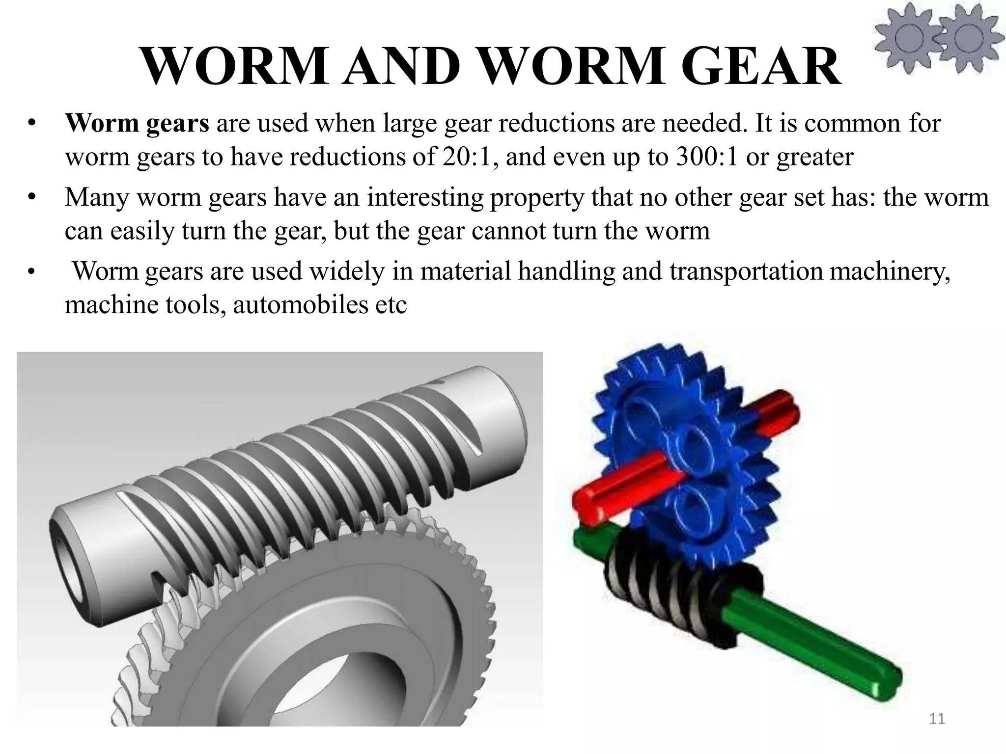
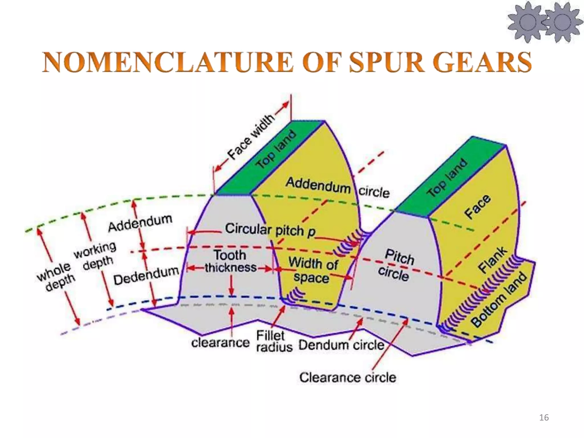
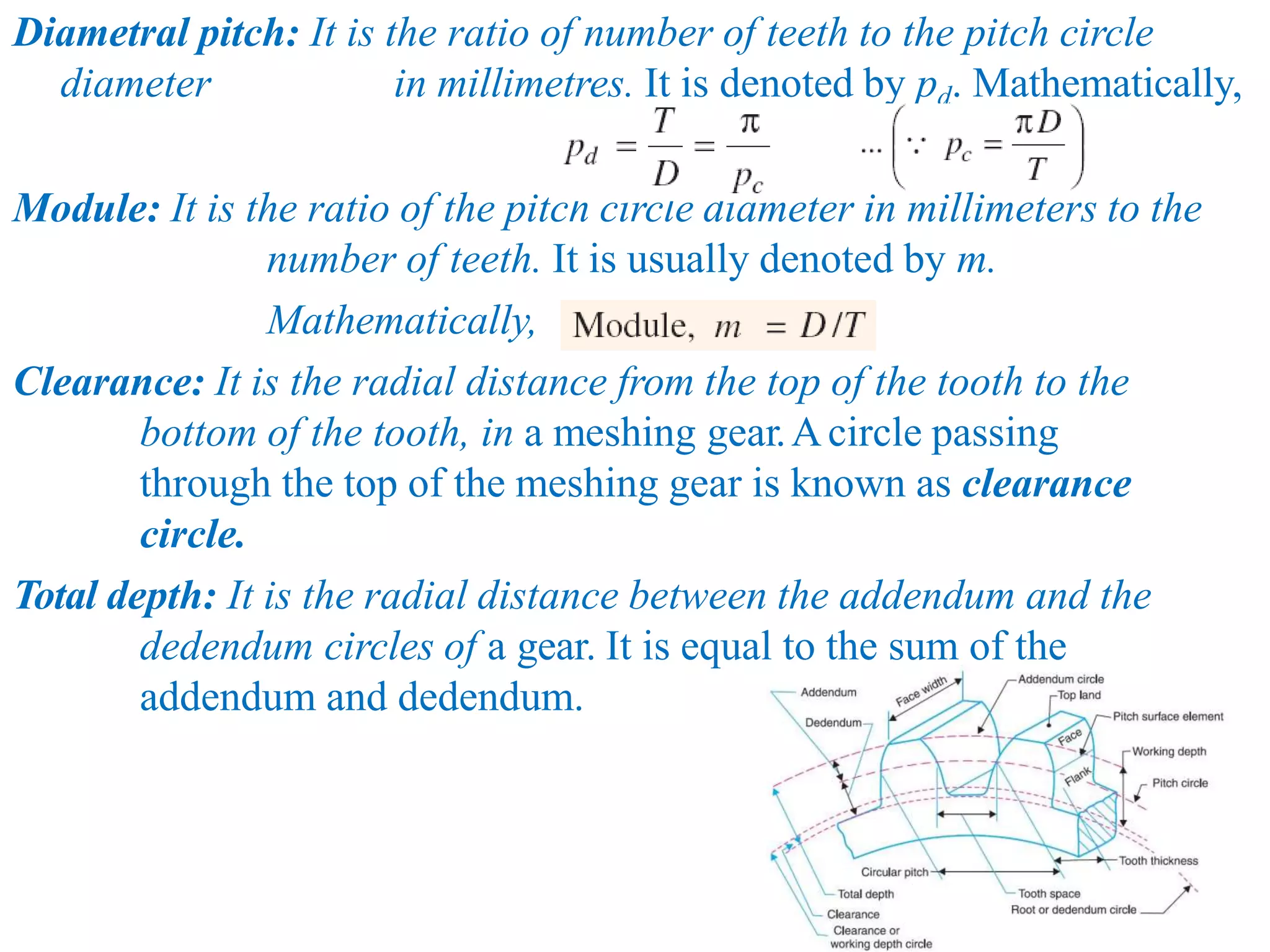
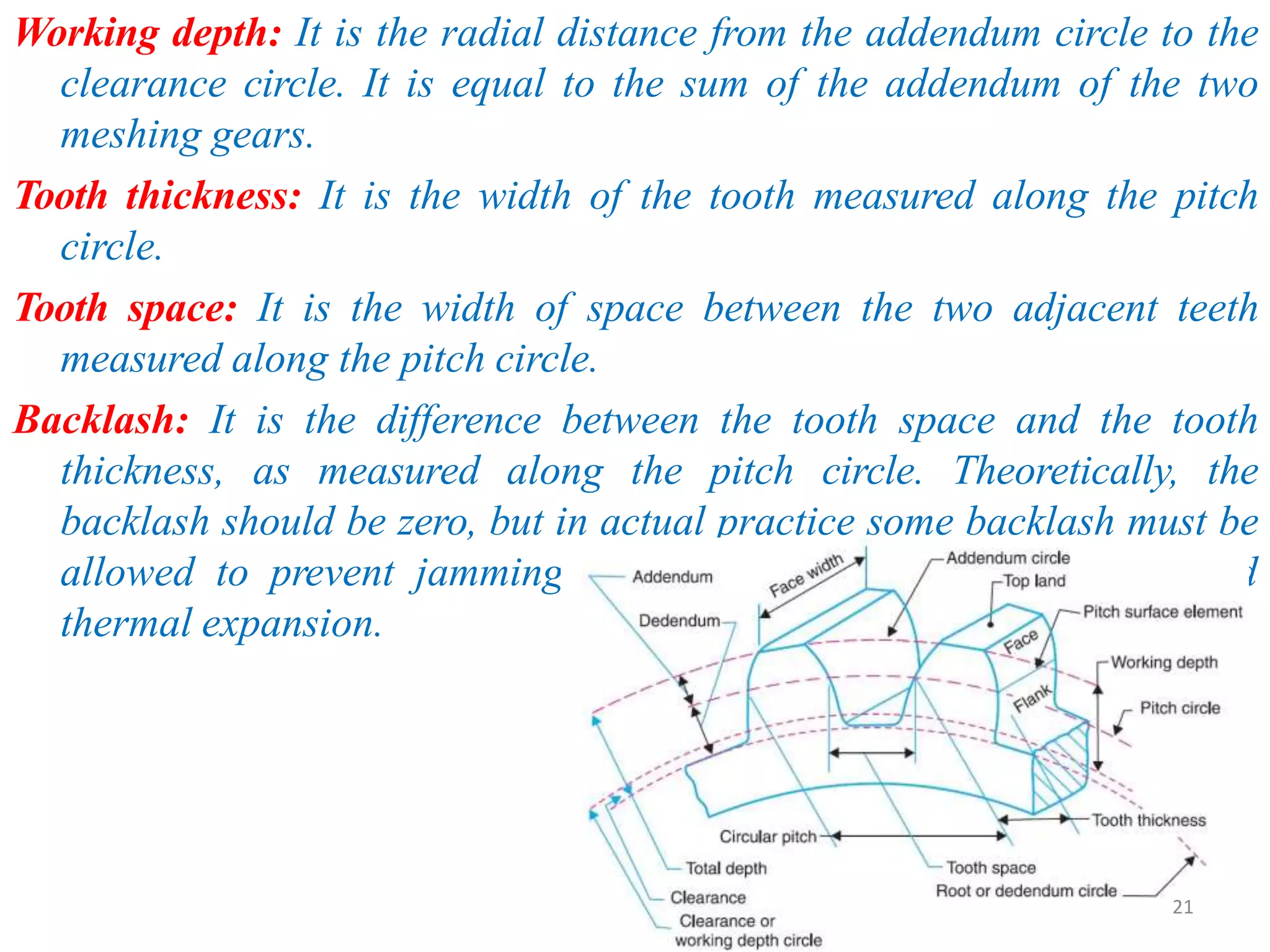
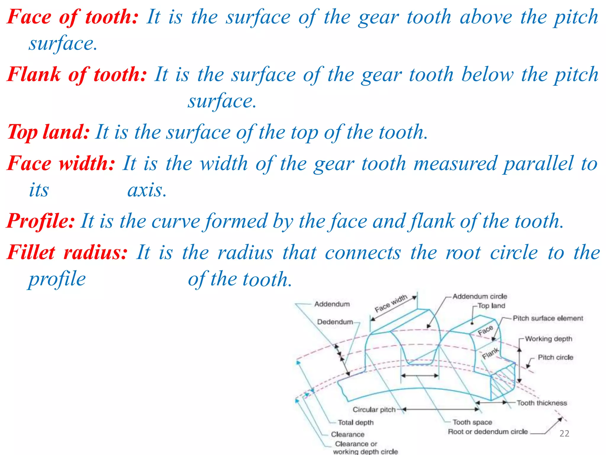
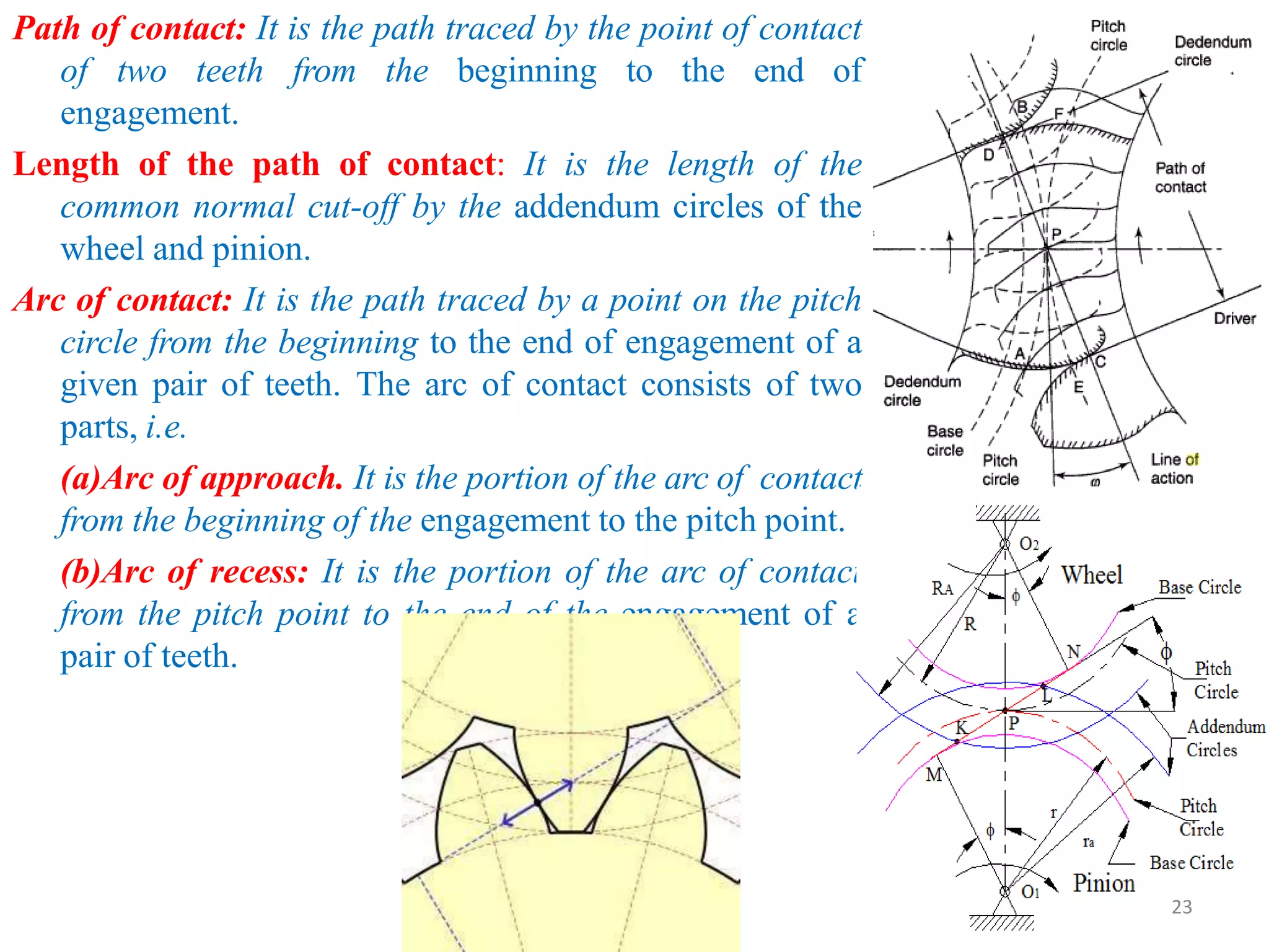
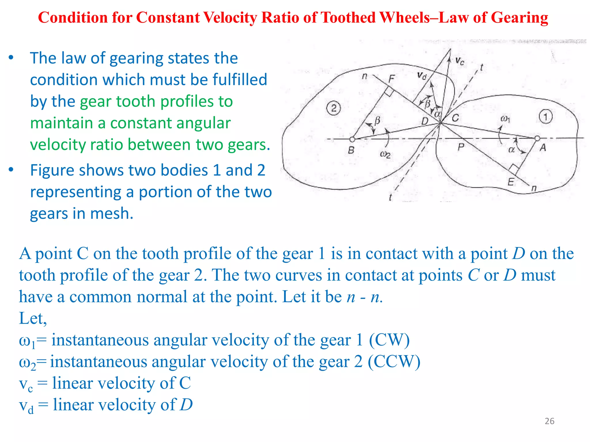
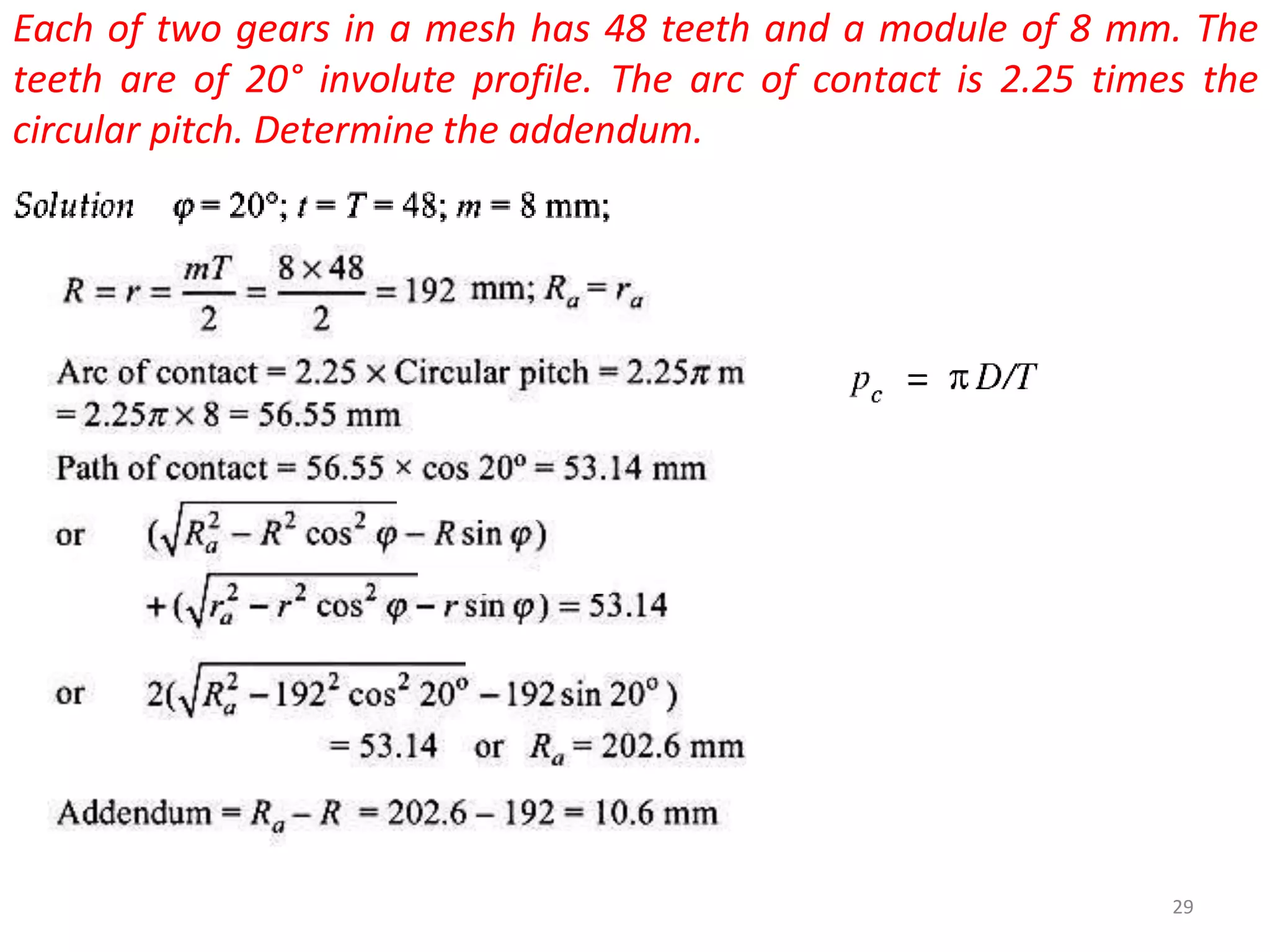
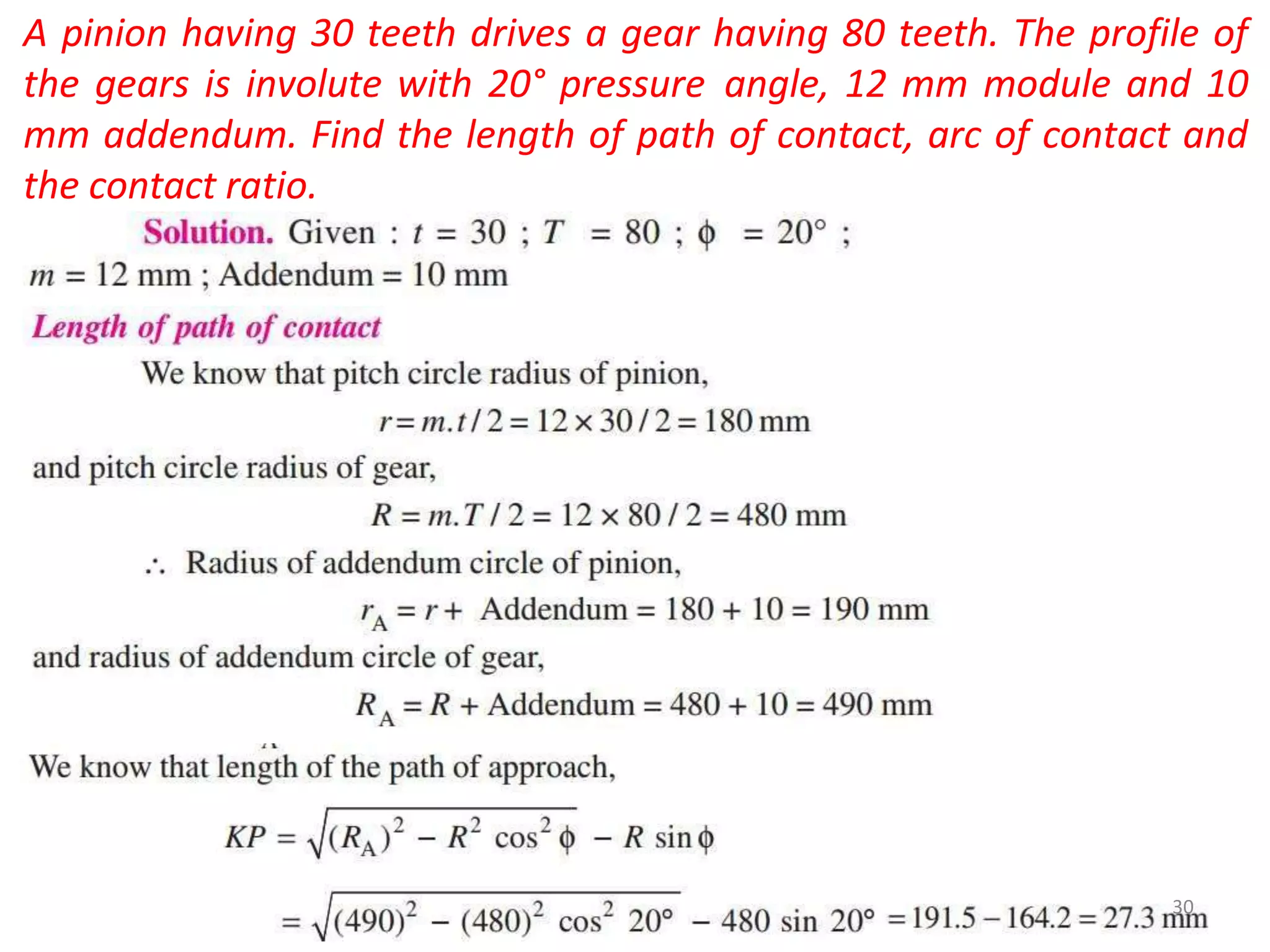
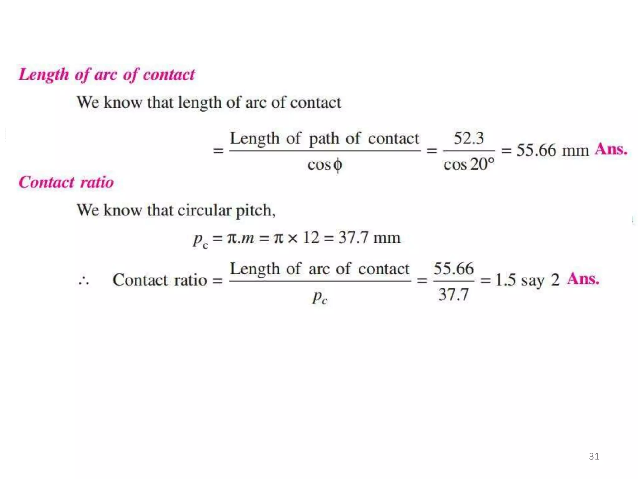
2. Introduction
• Gears are used to transfer motion and torque between machine components in
mechanical devices. Depending on the design and construction of the gear pair
employed, gears can change the direction of movement and/or increase the
output speed or torque.
• Let the wheel A be keyed to the rotating shaft and the wheel B to the shaft, to be
rotated.
• A little consideration will show, that when the wheel A is rotated by a rotating
shaft, it will rotate the wheel B in the opposite direction as shown in Fig. (a).
3
3. TYPES OF GEARS
1.According to the position of axes of the
shafts.
a. Parallel
1.Spur Gear
2.Helical Gear
3.Rack and Pinion
b. Intersecting
Bevel Gear
c. Non-intersecting and Non-parallel
worm and worm gears
3
4. SPUR GEAR
• Teeth is parallel to axis
of rotation
• Transmit power from
one shaft to another
parallel shaft
• Used in Electric
screwdriver, oscillating
sprinkler, windup alarm
clock, washing machine
and clothes dryer
4
6. Helical Gear
• The teeth on helical gears are cut at an angle to the face of the
gear
• This gradual engagement makes helical gears operate much
more smoothly and quietly than spur gears
• One interesting thing about helical gears is that if the angles
of the gear teeth are correct, they can be mounted on
perpendicular shafts, adjusting the rotation angle by 90
degrees
6
7. Herringbone gears
• To avoid axial thrust, two
helical gears of opposite
hand can be mounted side
by side, to cancel resulting
thrust forces
• Herringbone gears are
mostly used on heavy
machinery.
7
8. Rack and pinion
• Rack and pinion gears are used to convert rotation (From the
pinion) into linear motion (of the rack)
• Aperfect example of this is the steering system on many cars
3/29/2016 8
9. Bevel gears
• Bevel gears are useful when the direction of a shaft's rotation needs to
be changed
• They are usually mounted on shafts that are 90 degrees apart, but can
be designed to work at other angles as well
• The teeth on bevel gears can be straight, spiral or hypoid
• locomotives, marine applications, automobiles, printing presses,
cooling towers, power plants, steel plants, railway track inspection
machines, etc.
3/29/2016 9
11. WORM AND WORM GEAR
• Worm gears are used when large gear reductions are needed. It is common for
worm gears to have reductions of 20:1, and even up to 300:1 or greater
• Many worm gears have an interesting property that no other gear set has: the worm
can easily turn the gear, but the gear cannot turn the worm
• Worm gears are used widely in material handling and transportation machinery,
machine tools, automobiles etc
11
17. • Pitch circle: It is an imaginary circle which by pure rolling action
would give the same motion as the actual gear.
• Pitch circle diameter: It is the diameter of the pitch circle. The size of
the gear is usually specified by the pitch circle diameter. It is also
known as pitch diameter.
• Pitch point: It is a common point of contact between two pitch circles.
• Pressure angle or angle of obliquity: It is the angle between the
common normal to two gear teeth at the point of contact and the
common tangent at the pitch point. It is usually denoted by φ. The
standard pressure angles are 14 1/2 ° and 20°.
17
18. • Addendum: It is the radial distance of a tooth from the pitch circle to
the top of the tooth.
• Dedendum: It is the radial distance of a tooth from the pitch circle to
the bottom of the tooth.
• Addendum circle: It is the circle drawn through the top of the teeth
and is concentric with the pitch circle.
• Dedendum circle: It is the circle drawn through the bottom of the
teeth. It is also called root circle.
Note : Root circle diameter = Pitch circle diameter × cos φ
where φ is the pressure angle.
18
19. Circular pitch: It is the distance measured on the circumference of the
pitch circle from a point of one tooth to the corresponding point on
the next tooth. It is usually denoted by Pc ,Mathematically,
A little consideration will show that the two gears will mesh together
correctly, if the two wheels have the same circular pitch.
Note : If D1 and D2 are the diameters of the two meshing gears
having the teeth T1 and T2 respectively, then for them to mesh
correctly,
19
20. Diametral pitch: It is the ratio of number of teeth to the pitch circle
diameter in millimetres. It is denoted by pd. Mathematically,
Module: It is the ratio of the pitch circle diameter in millimeters to the
number of teeth. It is usually denoted by m.
Mathematically,
Clearance: It is the radial distance from the top of the tooth to the
bottom of the tooth, in a meshing gear.Acircle passing
through the top of the meshing gear is known as clearance
circle.
Total depth: It is the radial distance between the addendum and the
dedendum circles of a gear. It is equal to the sum of the
addendum and dedendum.
21. of the teeth due to tooth errors an
Working depth: It is the radial distance from the addendum circle to the
clearance circle. It is equal to the sum of the addendum of the two
meshing gears.
Tooth thickness: It is the width of the tooth measured along the pitch
circle.
Tooth space: It is the width of space between the two adjacent teeth
measured along the pitch circle.
Backlash: It is the difference between the tooth space and the tooth
thickness, as measured along the pitch circle. Theoretically, the
backlash should be zero, but in actual practice some backlash must be
allowed to prevent jamming d
thermal expansion.
21
22. Face of tooth: It is the surface of the gear tooth above the pitch
surface.
Flank of tooth: It is the surface of the gear tooth below the pitch
surface.
Top land: It is the surface of the top of the tooth.
Face width: It is the width of the gear tooth measured parallel to
its axis.
Profile: It is the curve formed by the face and flank of the tooth.
Fillet radius: It is the radius that connects the root circle to the
profile of the tooth.
22
23. Path of contact: It is the path traced by the point of contact
of two teeth from the beginning to the end of
engagement.
Length of the path of contact: It is the length of the
common normal cut-off by the addendum circles of the
wheel and pinion.
Arc of contact: It is the path traced by a point on the pitch
circle from the beginning to the end of engagement of a
given pair of teeth. The arc of contact consists of two
parts, i.e.
(a)Arc of approach. It is the portion of the arc of contact
from the beginning of the engagement to the pitch point.
(b)Arc of recess: It is the portion of the arc of contact
from the pitch point to the end of the engagement of a
pair of teeth.
23
24. two types of teeth
• In actual practice following are the
commonly used
1. Cycloidal teeth ; and 2. Involute teeth.
Cycloidal Teeth
• A cycloid is the curve traced by a point on the circumference of
a circle which rolls without slipping on a fixed straight line.
• When a circle rolls without slipping on the outside of a fixed
circle, the curve traced by a point on the circumference of a
circle is known as epi-cycloid.
• On the other hand, if a circle rolls without slipping on the
inside of a fixed circle, then the curve traced by a point on the
circumference of a circle is called hypo-cycloid.
24
26. Condition for Constant Velocity Ratio of Toothed Wheels–Law of Gearing
• The law of gearing states the
condition which must be fulfilled
by the gear tooth profiles to
maintain a constant angular
velocity ratio between two gears.
• Figure shows two bodies 1 and 2
representing a portion of the two
gears in mesh.
A point C on the tooth profile of the gear 1 is in contact with a point D on the
tooth profile of the gear 2. The two curves in contact at points C or D must
have a common normal at the point. Let it be n - n.
Let,
ω1= instantaneous angular velocity of the gear 1 (CW)
ω2= instantaneous angular velocity of the gear 2 (CCW)
vc = linear velocity of C
vd = linear velocity of D
26
27.
28.
29. Each of two gears in a mesh has 48 teeth and a module of 8 mm. The
teeth are of 20° involute profile. The arc of contact is 2.25 times the
circular pitch. Determine the addendum.
29
30. A pinion having 30 teeth drives a gear having 80 teeth. The profile of
the gears is involute with 20° pressure angle, 12 mm module and 10
mm addendum. Find the length of path of contact, arc of contact and
the contact ratio.
30
32. Two involute gears in mesh have 20o pressure angle. The gear ratio is 3
and the number of teeth on the pinion is 24. The teeth have a module of
6 mm. The pitch line velocity is 1.5 m/s and the addendum equal to one
module. Determine the angle of action of the pinion (the angle turned by
the pinion when one pair of teeth is in the mesh) and the maximum
velocity of sliding.
32