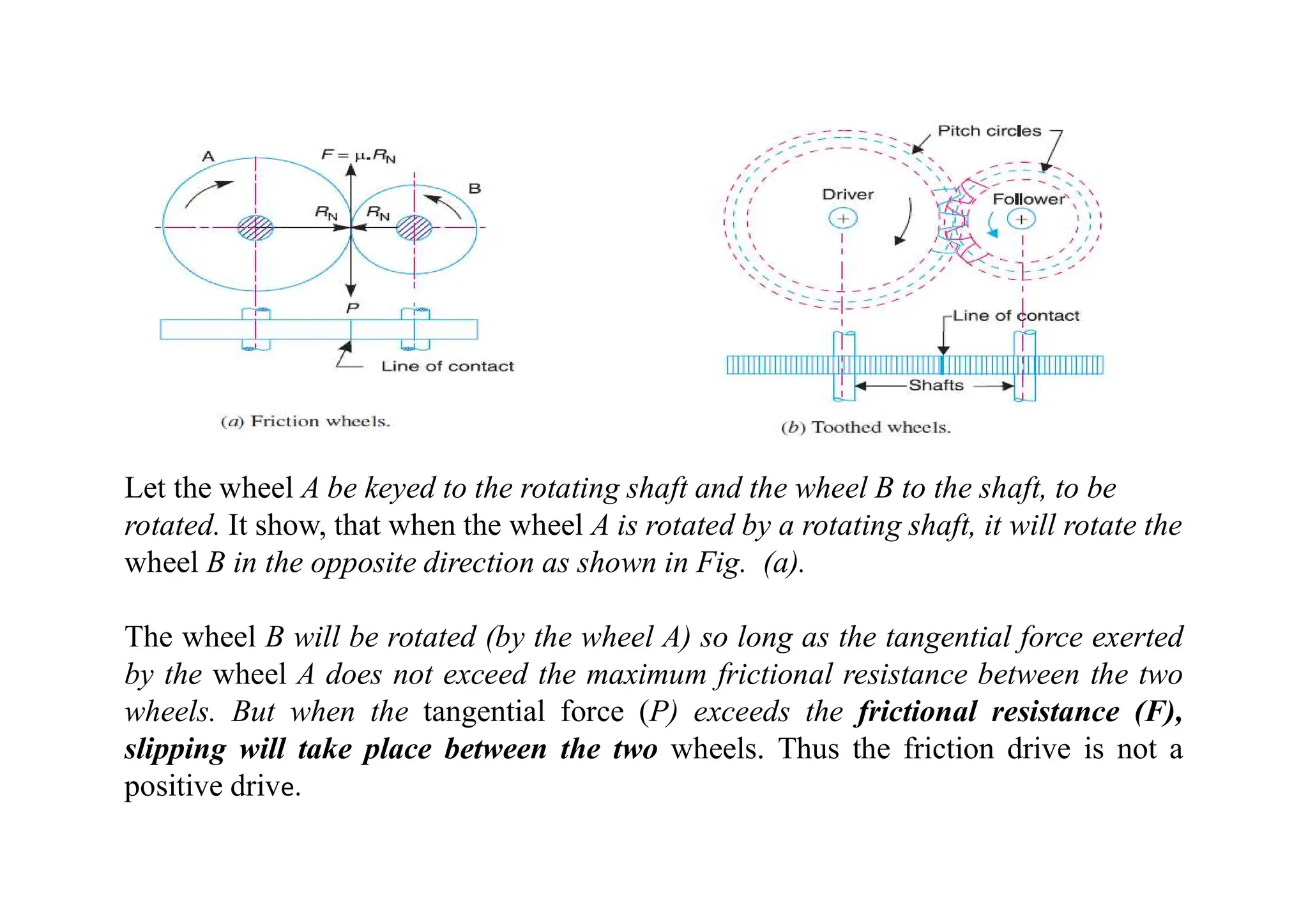
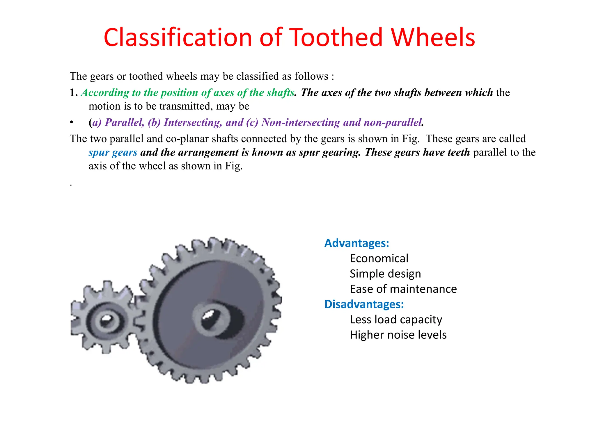
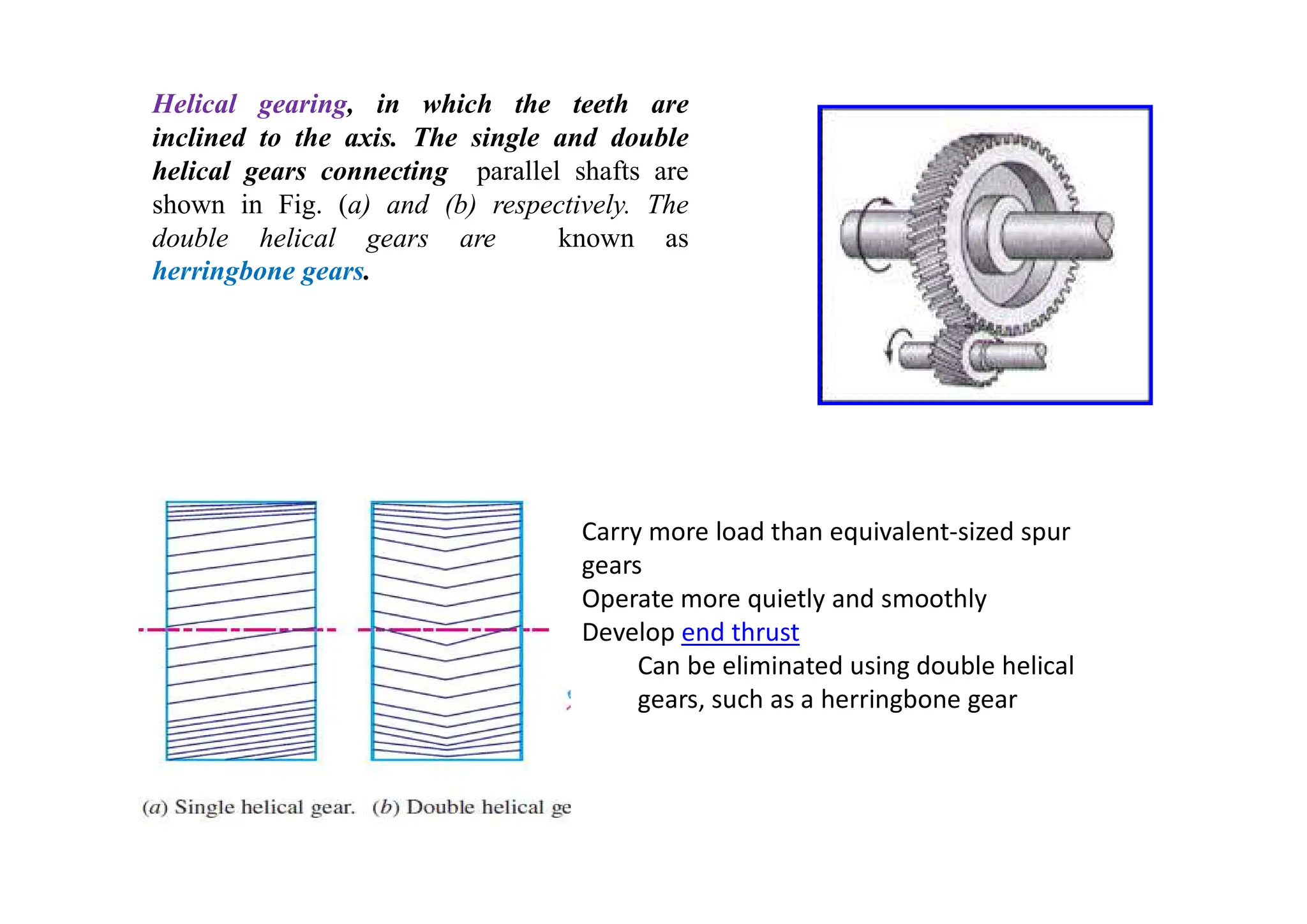
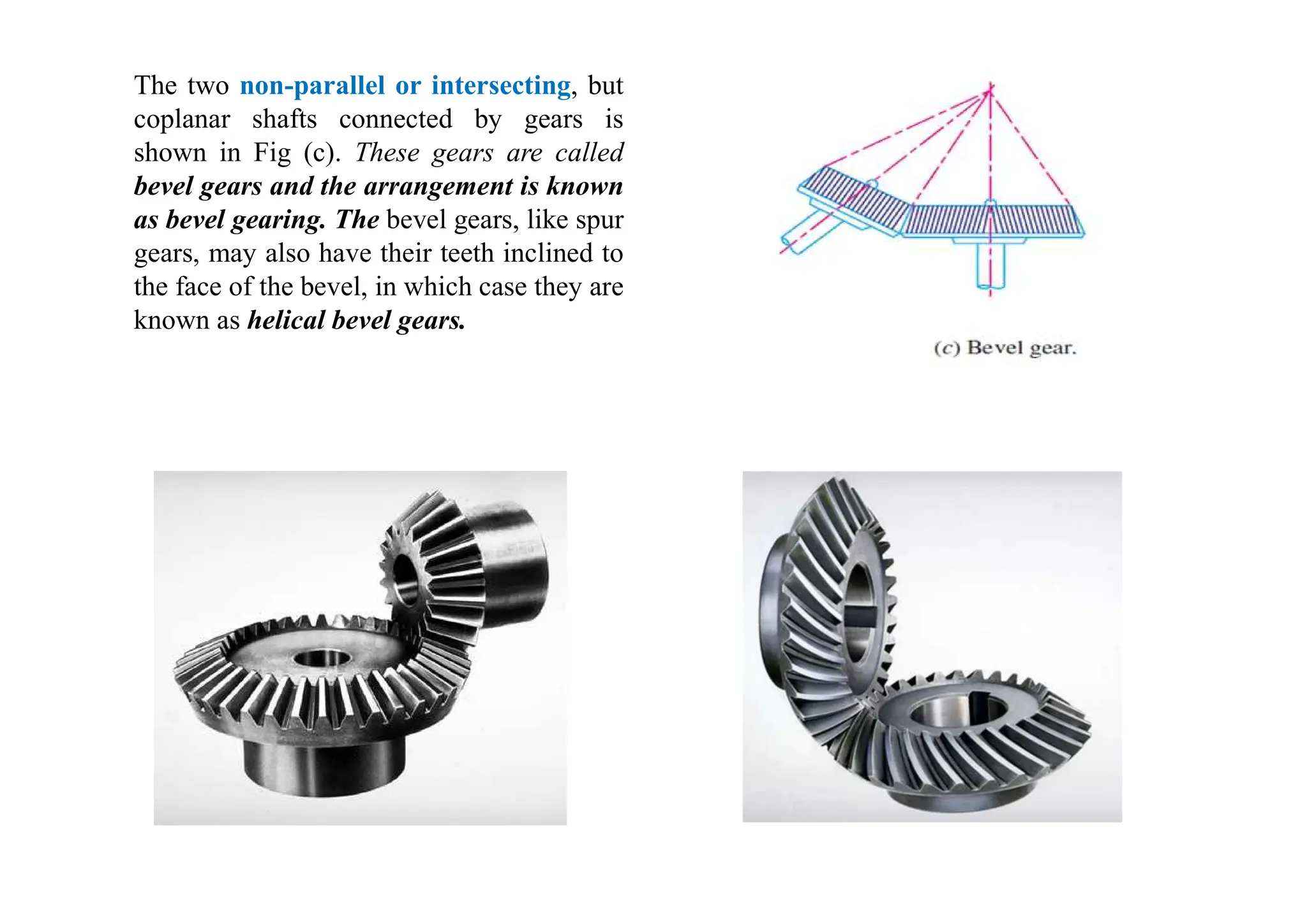
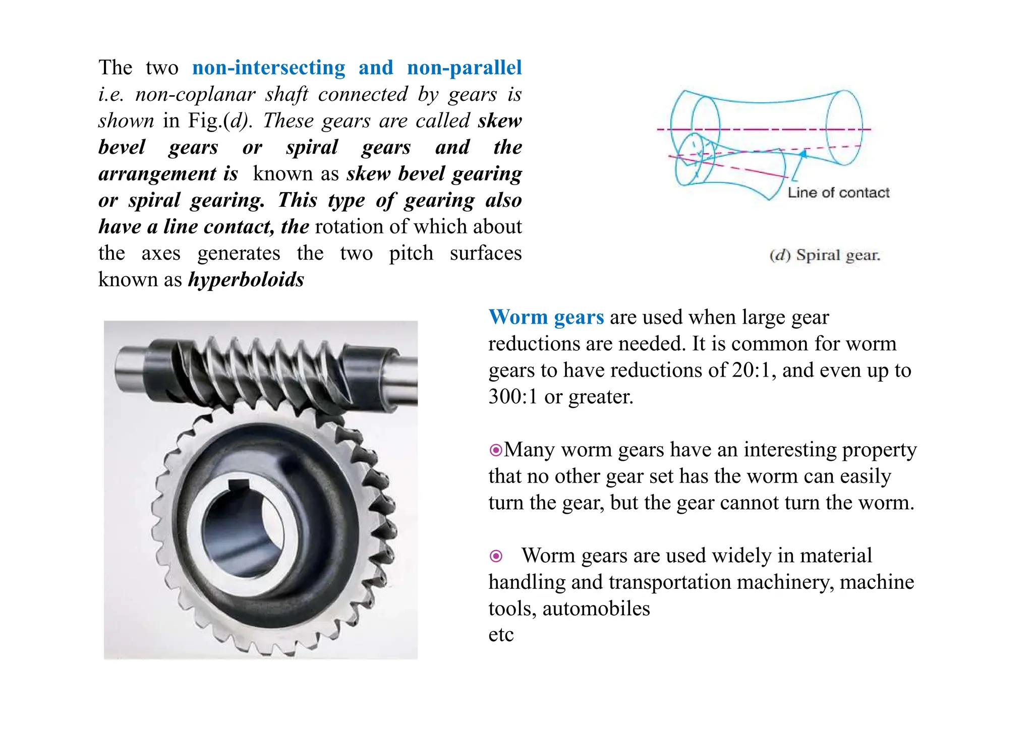
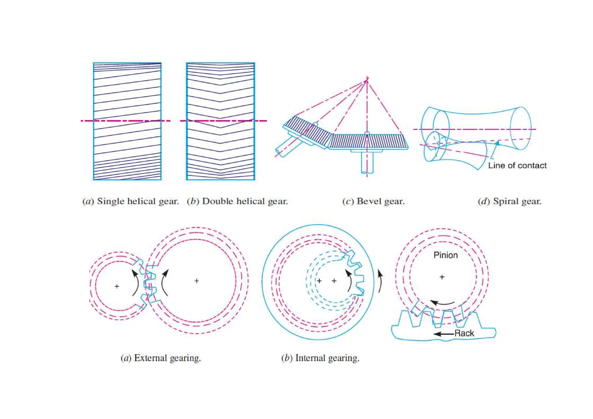
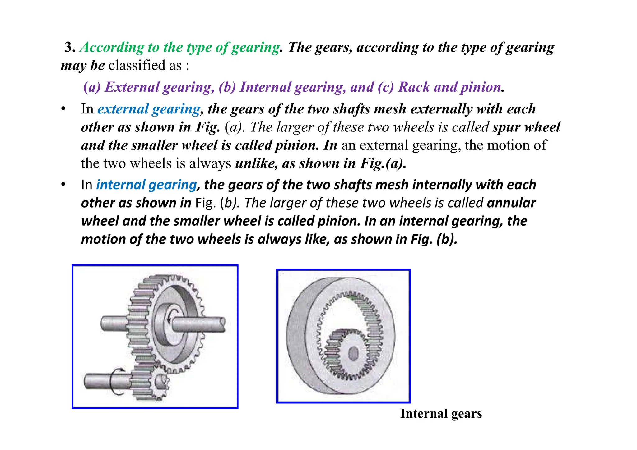
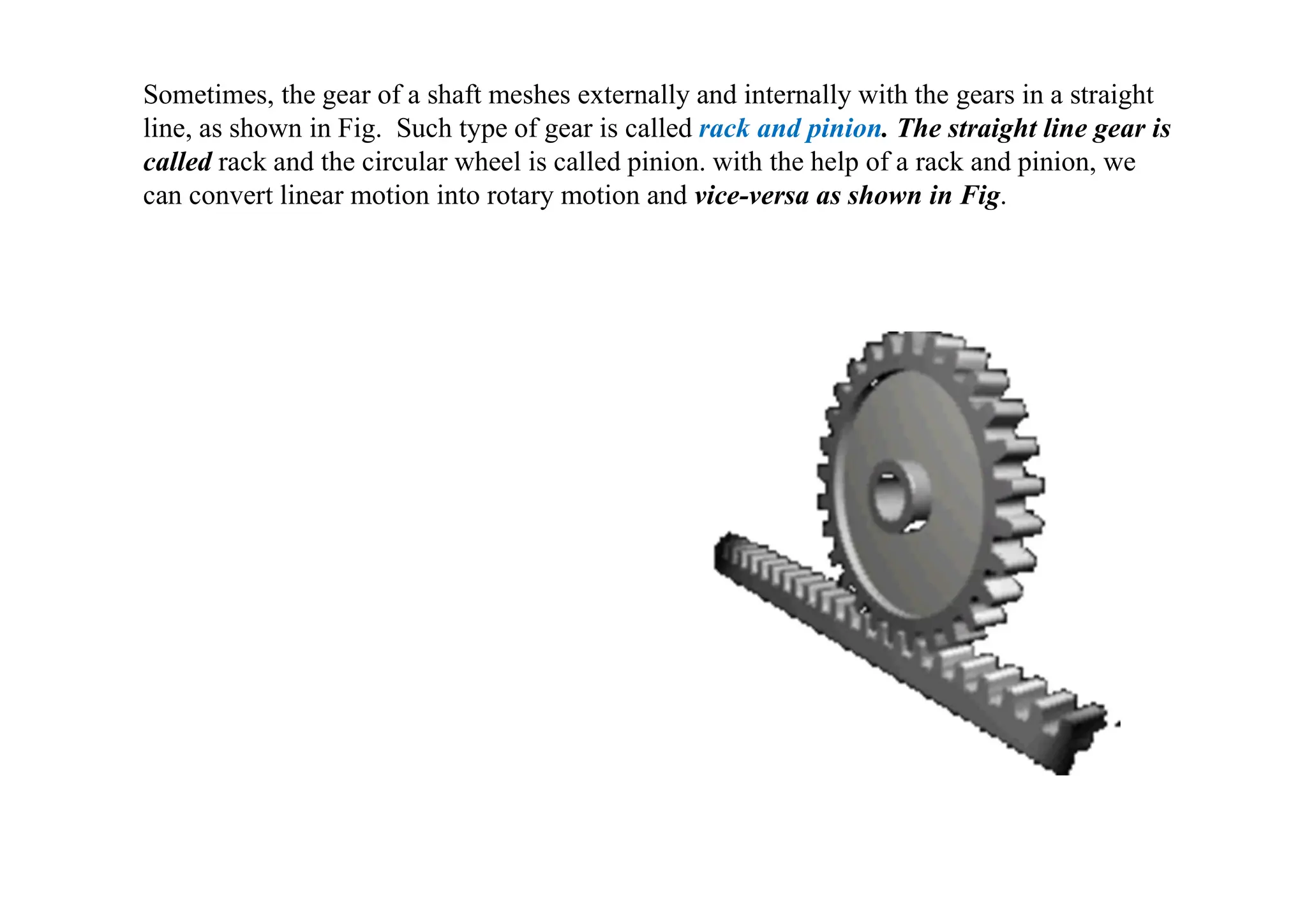
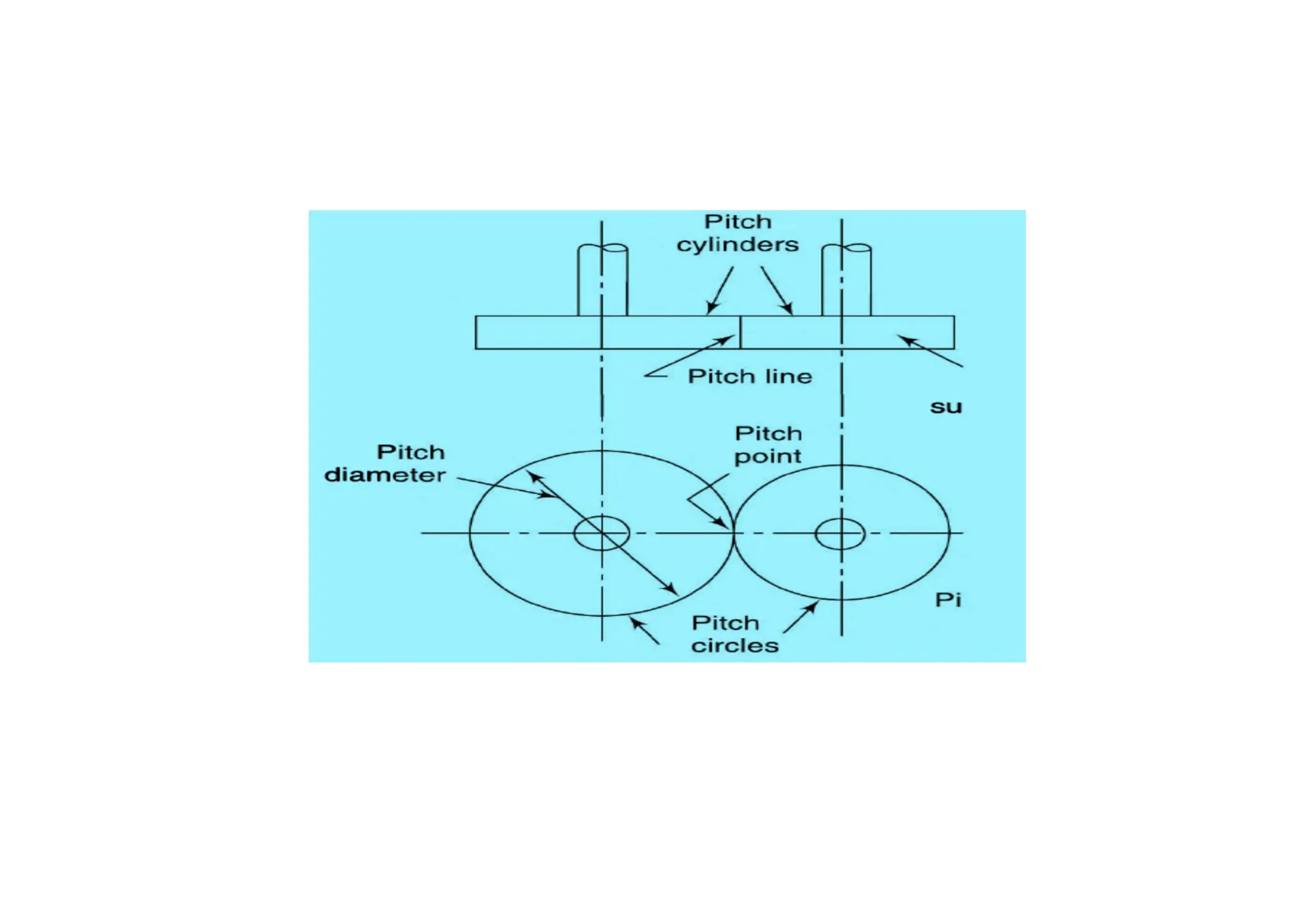
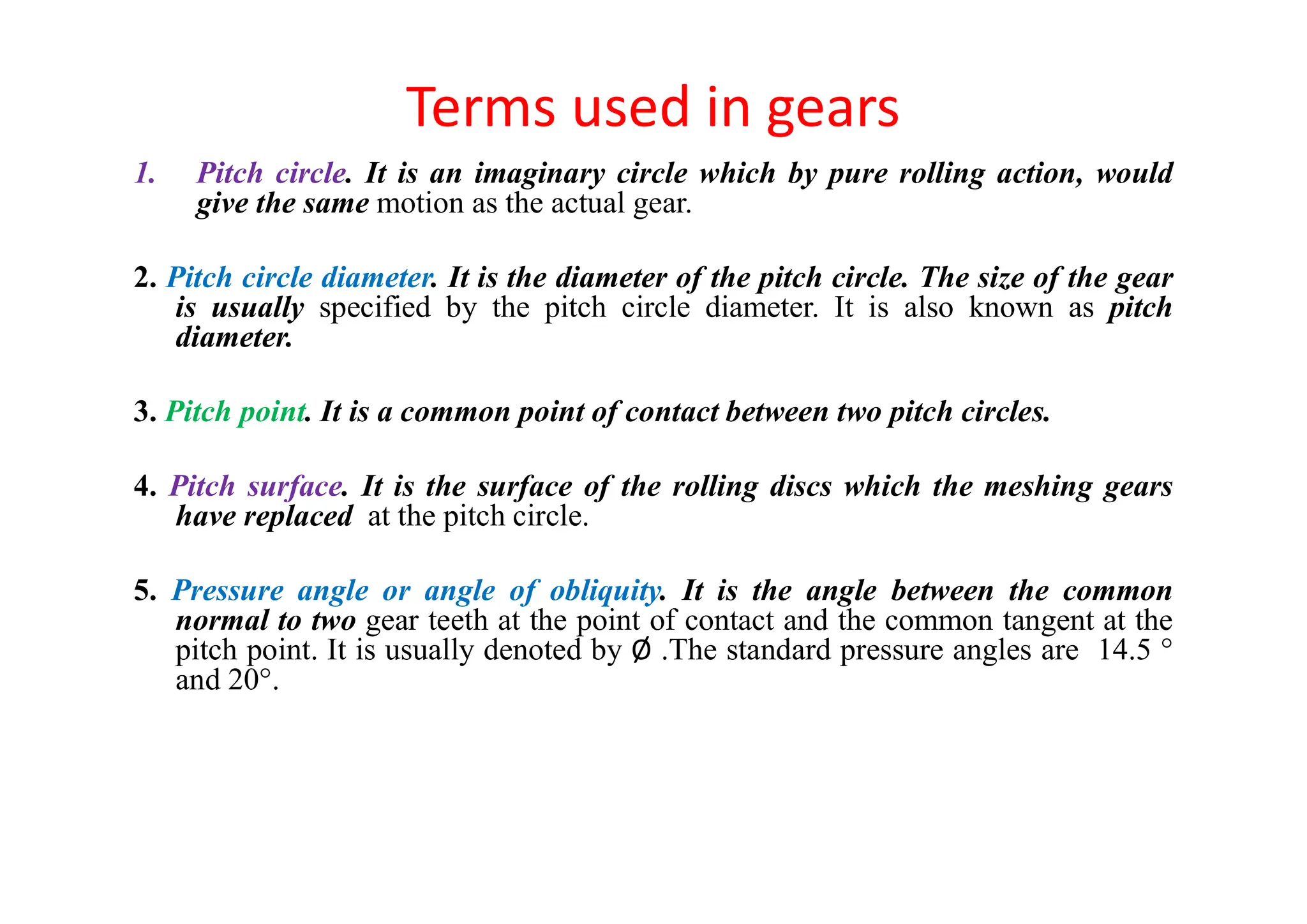
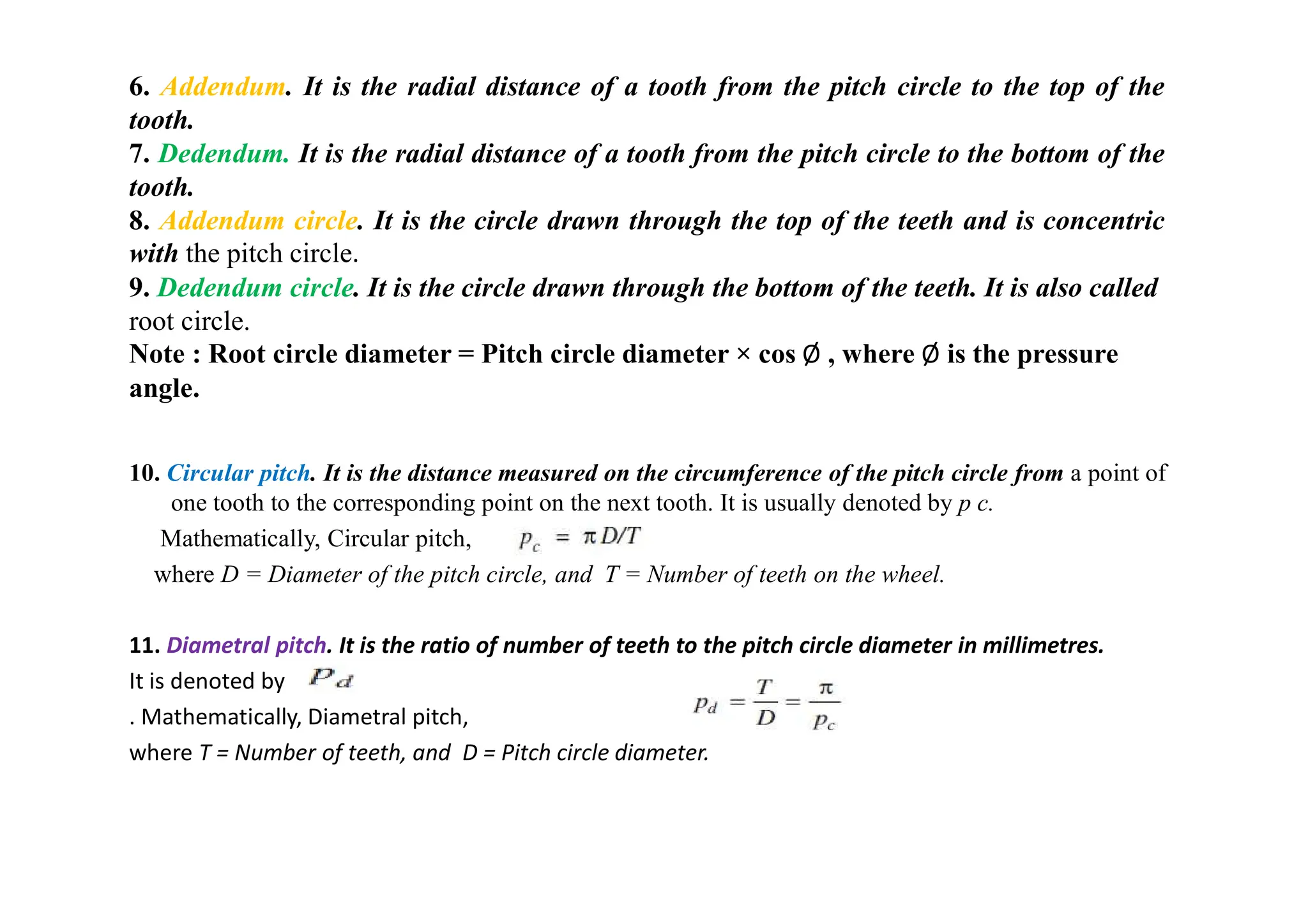
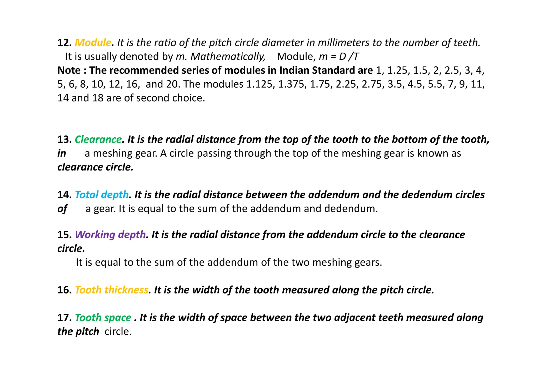
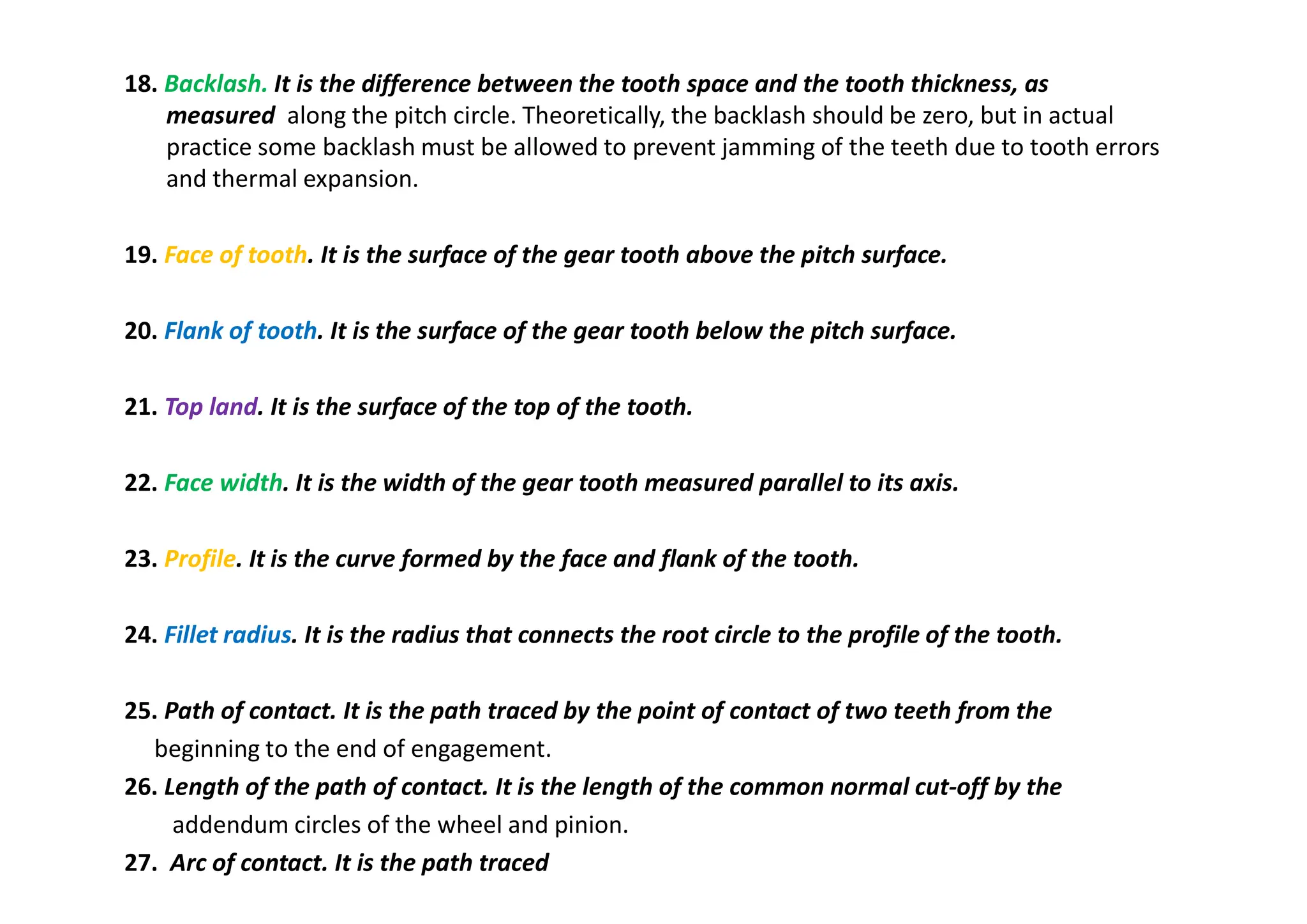
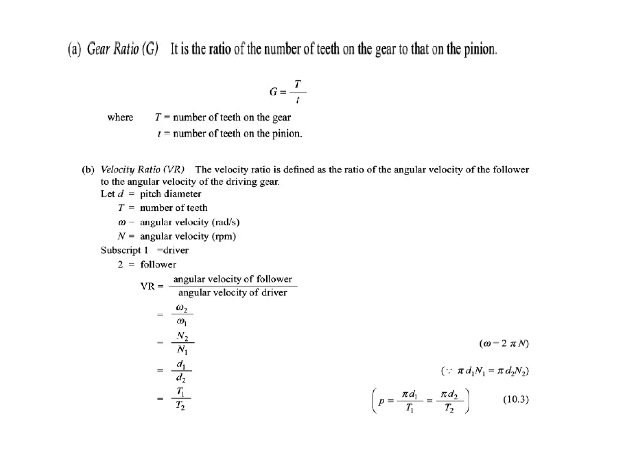
GEARS
Introduction
P KIRAN KUMAR
Assistant Professor
Mechanical Department, C.B.I.T.
List of content
•Introduction
•Advantages and disadvantages of gears
• Classification of gears
•Gear tooth terminology
Introduction
The slipping of a belt or rope is a common phenomenon, in the
transmission of motion or power between two shafts. The effect
of slipping is to reduce the velocity ratio of the system.
• In precision machines, in which a definite velocity ratio is of
importance (as in watch mechanism), the only positive drive is by
means of gears or toothed wheels.
A gear drive is also provided, when the distance between the driver
and the follower is very small.
• In order to understand how the motion can be transmitted by
two toothed wheels, consider two plain circular wheels A and B
mounted on shafts, having sufficient rough surfaces and
pressing against each other as shown in Fig. (a).
Let the wheel A be keyed to the rotating shaft and the wheel B to the shaft, to be
rotated. It show, that when the wheel A is rotated by a rotating shaft, it will rotate the
wheel B in the opposite direction as shown in Fig. (a).
The wheel B will be rotated (by the wheel A) so long as the tangential force exerted
by the wheel A does not exceed the maximum frictional resistance between the two
wheels. But when the tangential force (P) exceeds the frictional resistance (F),
slipping will take place between the two wheels. Thus the friction drive is not a
positive drive.
• In order to avoid the slipping, a number of projections (called teeth) as
shown in Fig.(b), are provided on the periphery of the wheel A, which will
fit into the corresponding recesses on the periphery of the wheel B. A
friction wheel with the teeth cut on it is known as toothed wheel or gear.
The usual connection to show the toothed wheels is by their pitch circles.
• Advantages
• 1. It transmits exact velocity ratio.
• 2. It may be used to transmit large power.
• 3. It has high efficiency.
• 4. It has reliable service.
• 5. It has compact layout.
Disadvantages
• 1. The manufacture of gears require special tools and equipment.
• 2. The error in cutting teeth may cause vibrations and noise during
operation
Classification of Toothed Wheels
The gears or toothed wheels may be classified as follows :
1. According to the position of axes of the shafts. The axes of the two shafts between which the
motion is to be transmitted, may be
• (a) Parallel, (b) Intersecting, and (c) Non-intersecting and non-parallel.
The two parallel and co-planar shafts connected by the gears is shown in Fig. These gears are called
spur gears and the arrangement is known as spur gearing. These gears have teeth parallel to the
axis of the wheel as shown in Fig.
.
Advantages:
Economical
Simple design
Ease of maintenance
Disadvantages:
Less load capacity
Higher noise levels
Helical gearing, in which the teeth are
inclined to the axis. The single and double
helical gears connecting parallel shafts are
shown in Fig. (a) and (b) respectively. The
double helical gears are known as
herringbone gears.
Carry more load than equivalent-sized spur
gears
Operate more quietly and smoothly
Develop end thrust
Can be eliminated using double helical
gears, such as a herringbone gear
The two non-parallel or intersecting, but
coplanar shafts connected by gears is
shown in Fig (c). These gears are called
bevel gears and the arrangement is known
as bevel gearing. The bevel gears, like spur
gears, may also have their teeth inclined to
the face of the bevel, in which case they are
known as helical bevel gears.
The two non-intersecting and non-parallel
i.e. non-coplanar shaft connected by gears is
shown in Fig.(d). These gears are called skew
bevel gears or spiral gears and the
arrangement is known as skew bevel gearing
or spiral gearing. This type of gearing also
have a line contact, the rotation of which about
the axes generates the two pitch surfaces
known as hyperboloids
Worm gears are used when large gear
reductions are needed. It is common for worm
gears to have reductions of 20:1, and even up to
300:1 or greater.
Many worm gears have an interesting property
that no other gear set has the worm can easily
turn the gear, but the gear cannot turn the worm.
 Worm gears are used widely in material
handling and transportation machinery, machine
tools, automobiles
etc
2. According to the peripheral velocity of the gears. The gears, according to the peripheral
velocity of the gears may be classified as :
(a) Low velocity, (b) Medium velocity, and (c) High velocity.
The gears having velocity less than 3 m/s are termed as low velocity gears and
gears having velocity between 3 and 15 m/s are known as medium velocity gears.
If the velocity of gears is more than 15 m/s, then these are called high speed gears
3. According to the type of gearing. The gears, according to the type of gearing
may be classified as :
(a) External gearing, (b) Internal gearing, and (c) Rack and pinion.
• In external gearing, the gears of the two shafts mesh externally with each
other as shown in Fig. (a). The larger of these two wheels is called spur wheel
and the smaller wheel is called pinion. In an external gearing, the motion of
the two wheels is always unlike, as shown in Fig.(a).
• In internal gearing, the gears of the two shafts mesh internally with each
other as shown in Fig. (b). The larger of these two wheels is called annular
wheel and the smaller wheel is called pinion. In an internal gearing, the
motion of the two wheels is always like, as shown in Fig. (b).
Internal gears
Sometimes, the gear of a shaft meshes externally and internally with the gears in a straight
line, as shown in Fig. Such type of gear is called rack and pinion. The straight line gear is
called rack and the circular wheel is called pinion. with the help of a rack and pinion, we
can convert linear motion into rotary motion and vice-versa as shown in Fig.
• 4. According to position of teeth on the gear surface. The teeth on the gear
surface may be
(a) straight, (b) inclined, and (c) curved.
We have discussed earlier that the spur gears have straight teeth where as helical gears have their teeth inclined to the wheel rim. In
case of spiral gears, the teeth are curved over the rim surface
Terms Used in Gears
Terms used in gears
1. Pitch circle. It is an imaginary circle which by pure rolling action, would
give the same motion as the actual gear.
2. Pitch circle diameter. It is the diameter of the pitch circle. The size of the gear
is usually specified by the pitch circle diameter. It is also known as pitch
diameter.
3. Pitch point. It is a common point of contact between two pitch circles.
4. Pitch surface. It is the surface of the rolling discs which the meshing gears
have replaced at the pitch circle.
5. Pressure angle or angle of obliquity. It is the angle between the common
normal to two gear teeth at the point of contact and the common tangent at the
pitch point. It is usually denoted by Ø .The standard pressure angles are 14.5 °
and 20°.
10. Circular pitch. It is the distance measured on the circumference of the pitch circle from a point of
one tooth to the corresponding point on the next tooth. It is usually denoted by p c.
Mathematically, Circular pitch,
where D = Diameter of the pitch circle, and T = Number of teeth on the wheel.
11. Diametral pitch. It is the ratio of number of teeth to the pitch circle diameter in millimetres.
It is denoted by
. Mathematically, Diametral pitch,
where T = Number of teeth, and D = Pitch circle diameter.
6. Addendum. It is the radial distance of a tooth from the pitch circle to the top of the
tooth.
7. Dedendum. It is the radial distance of a tooth from the pitch circle to the bottom of the
tooth.
8. Addendum circle. It is the circle drawn through the top of the teeth and is concentric
with the pitch circle.
9. Dedendum circle. It is the circle drawn through the bottom of the teeth. It is also called
root circle.
Note : Root circle diameter = Pitch circle diameter × cos Ø , where Ø is the pressure
angle.
12. Module. It is the ratio of the pitch circle diameter in millimeters to the number of teeth.
It is usually denoted by m. Mathematically, Module, m = D /T
Note : The recommended series of modules in Indian Standard are 1, 1.25, 1.5, 2, 2.5, 3, 4,
5, 6, 8, 10, 12, 16, and 20. The modules 1.125, 1.375, 1.75, 2.25, 2.75, 3.5, 4.5, 5.5, 7, 9, 11,
14 and 18 are of second choice.
13. Clearance. It is the radial distance from the top of the tooth to the bottom of the tooth,
in a meshing gear. A circle passing through the top of the meshing gear is known as
clearance circle.
14. Total depth. It is the radial distance between the addendum and the dedendum circles
of a gear. It is equal to the sum of the addendum and dedendum.
15. Working depth. It is the radial distance from the addendum circle to the clearance
circle.
It is equal to the sum of the addendum of the two meshing gears.
16. Tooth thickness. It is the width of the tooth measured along the pitch circle.
17. Tooth space . It is the width of space between the two adjacent teeth measured along
the pitch circle.
18. Backlash. It is the difference between the tooth space and the tooth thickness, as
measured along the pitch circle. Theoretically, the backlash should be zero, but in actual
practice some backlash must be allowed to prevent jamming of the teeth due to tooth errors
and thermal expansion.
19. Face of tooth. It is the surface of the gear tooth above the pitch surface.
20. Flank of tooth. It is the surface of the gear tooth below the pitch surface.
21. Top land. It is the surface of the top of the tooth.
22. Face width. It is the width of the gear tooth measured parallel to its axis.
23. Profile. It is the curve formed by the face and flank of the tooth.
24. Fillet radius. It is the radius that connects the root circle to the profile of the tooth.
25. Path of contact. It is the path traced by the point of contact of two teeth from the
beginning to the end of engagement.
26. Length of the path of contact. It is the length of the common normal cut-off by the
addendum circles of the wheel and pinion.
27. Arc of contact. It is the path traced
Comparison between Involute and Cycloidal Tooth Profiles
Gears gears gears gears gears gears gears

Gears gears gears gears gears gears gears

  • 1.
    GEARS Introduction P KIRAN KUMAR AssistantProfessor Mechanical Department, C.B.I.T.
  • 2.
    List of content •Introduction •Advantagesand disadvantages of gears • Classification of gears •Gear tooth terminology
  • 3.
    Introduction The slipping ofa belt or rope is a common phenomenon, in the transmission of motion or power between two shafts. The effect of slipping is to reduce the velocity ratio of the system. • In precision machines, in which a definite velocity ratio is of importance (as in watch mechanism), the only positive drive is by means of gears or toothed wheels. A gear drive is also provided, when the distance between the driver and the follower is very small. • In order to understand how the motion can be transmitted by two toothed wheels, consider two plain circular wheels A and B mounted on shafts, having sufficient rough surfaces and pressing against each other as shown in Fig. (a).
  • 4.
    Let the wheelA be keyed to the rotating shaft and the wheel B to the shaft, to be rotated. It show, that when the wheel A is rotated by a rotating shaft, it will rotate the wheel B in the opposite direction as shown in Fig. (a). The wheel B will be rotated (by the wheel A) so long as the tangential force exerted by the wheel A does not exceed the maximum frictional resistance between the two wheels. But when the tangential force (P) exceeds the frictional resistance (F), slipping will take place between the two wheels. Thus the friction drive is not a positive drive.
  • 5.
    • In orderto avoid the slipping, a number of projections (called teeth) as shown in Fig.(b), are provided on the periphery of the wheel A, which will fit into the corresponding recesses on the periphery of the wheel B. A friction wheel with the teeth cut on it is known as toothed wheel or gear. The usual connection to show the toothed wheels is by their pitch circles. • Advantages • 1. It transmits exact velocity ratio. • 2. It may be used to transmit large power. • 3. It has high efficiency. • 4. It has reliable service. • 5. It has compact layout. Disadvantages • 1. The manufacture of gears require special tools and equipment. • 2. The error in cutting teeth may cause vibrations and noise during operation
  • 6.
    Classification of ToothedWheels The gears or toothed wheels may be classified as follows : 1. According to the position of axes of the shafts. The axes of the two shafts between which the motion is to be transmitted, may be • (a) Parallel, (b) Intersecting, and (c) Non-intersecting and non-parallel. The two parallel and co-planar shafts connected by the gears is shown in Fig. These gears are called spur gears and the arrangement is known as spur gearing. These gears have teeth parallel to the axis of the wheel as shown in Fig. . Advantages: Economical Simple design Ease of maintenance Disadvantages: Less load capacity Higher noise levels
  • 7.
    Helical gearing, inwhich the teeth are inclined to the axis. The single and double helical gears connecting parallel shafts are shown in Fig. (a) and (b) respectively. The double helical gears are known as herringbone gears. Carry more load than equivalent-sized spur gears Operate more quietly and smoothly Develop end thrust Can be eliminated using double helical gears, such as a herringbone gear
  • 8.
    The two non-parallelor intersecting, but coplanar shafts connected by gears is shown in Fig (c). These gears are called bevel gears and the arrangement is known as bevel gearing. The bevel gears, like spur gears, may also have their teeth inclined to the face of the bevel, in which case they are known as helical bevel gears.
  • 9.
    The two non-intersectingand non-parallel i.e. non-coplanar shaft connected by gears is shown in Fig.(d). These gears are called skew bevel gears or spiral gears and the arrangement is known as skew bevel gearing or spiral gearing. This type of gearing also have a line contact, the rotation of which about the axes generates the two pitch surfaces known as hyperboloids Worm gears are used when large gear reductions are needed. It is common for worm gears to have reductions of 20:1, and even up to 300:1 or greater. Many worm gears have an interesting property that no other gear set has the worm can easily turn the gear, but the gear cannot turn the worm.  Worm gears are used widely in material handling and transportation machinery, machine tools, automobiles etc
  • 11.
    2. According tothe peripheral velocity of the gears. The gears, according to the peripheral velocity of the gears may be classified as : (a) Low velocity, (b) Medium velocity, and (c) High velocity. The gears having velocity less than 3 m/s are termed as low velocity gears and gears having velocity between 3 and 15 m/s are known as medium velocity gears. If the velocity of gears is more than 15 m/s, then these are called high speed gears
  • 12.
    3. According tothe type of gearing. The gears, according to the type of gearing may be classified as : (a) External gearing, (b) Internal gearing, and (c) Rack and pinion. • In external gearing, the gears of the two shafts mesh externally with each other as shown in Fig. (a). The larger of these two wheels is called spur wheel and the smaller wheel is called pinion. In an external gearing, the motion of the two wheels is always unlike, as shown in Fig.(a). • In internal gearing, the gears of the two shafts mesh internally with each other as shown in Fig. (b). The larger of these two wheels is called annular wheel and the smaller wheel is called pinion. In an internal gearing, the motion of the two wheels is always like, as shown in Fig. (b). Internal gears
  • 13.
    Sometimes, the gearof a shaft meshes externally and internally with the gears in a straight line, as shown in Fig. Such type of gear is called rack and pinion. The straight line gear is called rack and the circular wheel is called pinion. with the help of a rack and pinion, we can convert linear motion into rotary motion and vice-versa as shown in Fig.
  • 14.
    • 4. Accordingto position of teeth on the gear surface. The teeth on the gear surface may be (a) straight, (b) inclined, and (c) curved. We have discussed earlier that the spur gears have straight teeth where as helical gears have their teeth inclined to the wheel rim. In case of spiral gears, the teeth are curved over the rim surface
  • 15.
  • 17.
    Terms used ingears 1. Pitch circle. It is an imaginary circle which by pure rolling action, would give the same motion as the actual gear. 2. Pitch circle diameter. It is the diameter of the pitch circle. The size of the gear is usually specified by the pitch circle diameter. It is also known as pitch diameter. 3. Pitch point. It is a common point of contact between two pitch circles. 4. Pitch surface. It is the surface of the rolling discs which the meshing gears have replaced at the pitch circle. 5. Pressure angle or angle of obliquity. It is the angle between the common normal to two gear teeth at the point of contact and the common tangent at the pitch point. It is usually denoted by Ø .The standard pressure angles are 14.5 ° and 20°.
  • 18.
    10. Circular pitch.It is the distance measured on the circumference of the pitch circle from a point of one tooth to the corresponding point on the next tooth. It is usually denoted by p c. Mathematically, Circular pitch, where D = Diameter of the pitch circle, and T = Number of teeth on the wheel. 11. Diametral pitch. It is the ratio of number of teeth to the pitch circle diameter in millimetres. It is denoted by . Mathematically, Diametral pitch, where T = Number of teeth, and D = Pitch circle diameter. 6. Addendum. It is the radial distance of a tooth from the pitch circle to the top of the tooth. 7. Dedendum. It is the radial distance of a tooth from the pitch circle to the bottom of the tooth. 8. Addendum circle. It is the circle drawn through the top of the teeth and is concentric with the pitch circle. 9. Dedendum circle. It is the circle drawn through the bottom of the teeth. It is also called root circle. Note : Root circle diameter = Pitch circle diameter × cos Ø , where Ø is the pressure angle.
  • 19.
    12. Module. Itis the ratio of the pitch circle diameter in millimeters to the number of teeth. It is usually denoted by m. Mathematically, Module, m = D /T Note : The recommended series of modules in Indian Standard are 1, 1.25, 1.5, 2, 2.5, 3, 4, 5, 6, 8, 10, 12, 16, and 20. The modules 1.125, 1.375, 1.75, 2.25, 2.75, 3.5, 4.5, 5.5, 7, 9, 11, 14 and 18 are of second choice. 13. Clearance. It is the radial distance from the top of the tooth to the bottom of the tooth, in a meshing gear. A circle passing through the top of the meshing gear is known as clearance circle. 14. Total depth. It is the radial distance between the addendum and the dedendum circles of a gear. It is equal to the sum of the addendum and dedendum. 15. Working depth. It is the radial distance from the addendum circle to the clearance circle. It is equal to the sum of the addendum of the two meshing gears. 16. Tooth thickness. It is the width of the tooth measured along the pitch circle. 17. Tooth space . It is the width of space between the two adjacent teeth measured along the pitch circle.
  • 20.
    18. Backlash. Itis the difference between the tooth space and the tooth thickness, as measured along the pitch circle. Theoretically, the backlash should be zero, but in actual practice some backlash must be allowed to prevent jamming of the teeth due to tooth errors and thermal expansion. 19. Face of tooth. It is the surface of the gear tooth above the pitch surface. 20. Flank of tooth. It is the surface of the gear tooth below the pitch surface. 21. Top land. It is the surface of the top of the tooth. 22. Face width. It is the width of the gear tooth measured parallel to its axis. 23. Profile. It is the curve formed by the face and flank of the tooth. 24. Fillet radius. It is the radius that connects the root circle to the profile of the tooth. 25. Path of contact. It is the path traced by the point of contact of two teeth from the beginning to the end of engagement. 26. Length of the path of contact. It is the length of the common normal cut-off by the addendum circles of the wheel and pinion. 27. Arc of contact. It is the path traced
  • 32.
    Comparison between Involuteand Cycloidal Tooth Profiles