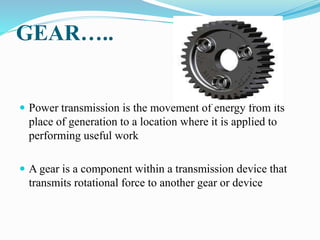
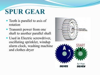
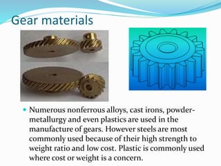
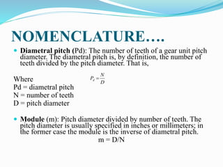
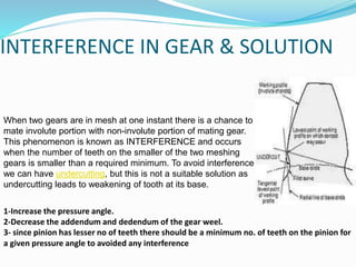
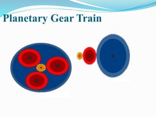
GEAR TOOTH DESIGN AND GEAR
TRAINS
Prepared By:
Jagtam Sharan
ME 3rd year
CONTENTS
•POWER TRANSMISSION
•GEAR
•TYPES OF GEARS
•NOMENCLATURE
•DESIGN OF INVOLUTE GEAR TEETH
•APPLICATIONS OF GEARS
•VELOCITY RATIO
•GEAR TRAINS
•QUESTIONS
GEAR…..
 Power transmission is the movement of energy from its
place of generation to a location where it is applied to
performing useful work
 A gear is a component within a transmission device that
transmits rotational force to another gear or device
MOTION OF GEAR
TYPES OF GEARS
1. According to the position of axes of the shafts.
a. Parallel
1.Spur Gear
2.Helical Gear
3.Rack and Pinion
b. Intersecting
Bevel Gear
c. Non-intersecting and Non-parallel
worm and worm gears
SPUR GEAR
 Teeth is parallel to axis of
rotation
 Transmit power from one
shaft to another parallel shaft
 Used in Electric screwdriver,
oscillating sprinkler, windup
alarm clock, washing machine
and clothes dryer
External and Internal spur Gear…
Spur Gear
Helical Gear
 The teeth on helical gears are cut at an angle to the face of the
gear
 This gradual engagement makes helical gears operate much
more smoothly and quietly than spur gears
 One interesting thing about helical gears is that if the angles of
the gear teeth are correct, they can be mounted on perpendicular
shafts, adjusting the rotation angle by 90 degrees
Helical Gear…
Herringbone gears
 To avoid axial thrust, two
helical gears of opposite
hand can be mounted side by
side, to cancel resulting
thrust forces
 Herringbone gears are
mostly used on heavy
machinery.
Helical Gear
Rack and pinion
 Rack and pinion gears are used to convert rotation (From the
pinion) into linear motion (of the rack)
 A perfect example of this is the steering system on many cars
Harmonic drive gear
Bevel gears
 Bevel gears are useful when the direction of a shaft's
rotation needs to be changed
 They are usually mounted on shafts that are 90
degrees apart, but can be designed to work at other
angles as well
 The teeth on bevel gears can be straight, spiral or
hypoid
 locomotives, marine applications, automobiles,
printing presses, cooling towers, power plants, steel
plants, railway track inspection machines, etc.
Straight and Spiral Bevel Gears
WORM AND WORM GEAR
 Worm gears are used when large gear reductions are
needed. It is common for worm gears to have
reductions of 20:1, and even up to 300:1 or greater
 Many worm gears have an interesting property that
no other gear set has: the worm can easily turn the
gear, but the gear cannot turn the worm
 Worm gears are used widely in material handling and
transportation machinery, machine tools, automobiles
etc
WORM AND WORM GEAR
WORM AND WORM GEAR
Gear materials
 Numerous nonferrous alloys, cast irons, powder-
metallurgy and even plastics are used in the
manufacture of gears. However steels are most
commonly used because of their high strength to
weight ratio and low cost. Plastic is commonly used
where cost or weight is a concern.
NOMENCLATURE OF SPUR
GEARS
NOMENCLATURE….
 Pitch surface: The surface of the imaginary rolling cylinder
(cone, etc.) that the toothed gear may be considered to replace.
 Pitch circle: A right section of the pitch surface.
 Addendum circle: A circle bounding the ends of the teeth, in a
right section of the gear.
 Root (or dedendum) circle: The circle bounding the spaces
between the teeth, in a right section of the gear.
 Addendum: The radial distance between the pitch circle and
the addendum circle.
 Dedendum: The radial distance between the pitch circle and
the root circle.
 Clearance: The difference between the dedendum of one gear
and the addendum of the mating gear.
NOMENCLATURE….
 Face of a tooth: That part of the tooth surface lying outside the
pitch surface.
 Flank of a tooth: The part of the tooth surface lying inside the
pitch surface.
 Circular thickness (also called the tooth thickness): The
thickness of the tooth measured on the pitch circle. It is the
length of an arc and not the length of a straight line.
 Tooth space: pitch diameter The distance between adjacent
teeth measured on the pitch circle.
 Backlash: The difference between the circle thickness of one
gear and the tooth space of the mating gear.
 Circular pitch (Pc) : The width of a tooth and a space,
measured on the pitch circle.
N
D
Pc

NOMENCLATURE….
 Diametral pitch (Pd): The number of teeth of a gear unit pitch
diameter. The diametral pitch is, by definition, the number of
teeth divided by the pitch diameter. That is,
Where
Pd = diametral pitch
N = number of teeth
D = pitch diameter
 Module (m): Pitch diameter divided by number of teeth. The
pitch diameter is usually specified in inches or millimeters; in
the former case the module is the inverse of diametral pitch.
m = D/N
D
N
Pd 
Fundamental Law of Gear-Tooth
Action
 two mating gear teeth, in which
 Tooth profile 1 drives tooth profile 2 by acting at the instantaneous
contact point K.
 N1N2 is the common normal of the two profiles.
 N1 is the foot of the perpendicular from O1 to N1N2
 N2 is the foot of the perpendicular from O2 to N1N2.
1.INVOLUTE PROFILE TEETH
2.CYCLOIDAL PROFILE TEETH
Design 0f Involute profile teeth
Cycloidal profile teeth
VELOCITY RATIO OF GEAR
DRIVE
d = Diameter of the wheel
N =Speed of the wheel
ω = Angular speed
velocity ratio (n) =
2
1
1
2
1
2
d
d
N
N



INTERFERENCE IN GEAR & SOLUTION
When two gears are in mesh at one instant there is a chance to
mate involute portion with non-involute portion of mating gear.
This phenomenon is known as INTERFERENCE and occurs
when the number of teeth on the smaller of the two meshing
gears is smaller than a required minimum. To avoid interference
we can have undercutting, but this is not a suitable solution as
undercutting leads to weakening of tooth at its base.
1-Increase the pressure angle.
2-Decrease the addendum and dedendum of the gear weel.
3- since pinion has lesser no of teeth there should be a minimum no. of teeth on the pinion for
a given pressure angle to avoided any interference
INTERFERENCE IN GEAR &
UNDERCUTTING
GEAR TRAINS
 A gear train is two or more gear working together by
meshing their teeth and turning each other in a system to
generate power and speed
 It reduces speed and increases torque
 Electric motors are used with the gear systems to reduce
the speed and increase the torque
GEAR TRAINS
Types of Gear Trains
 Simple gear train
 Compound gear train
 Planetary gear train
 Reverted gear train
Simple Gear Train
1.The most common of the gear train is the
gear pair connecting parallel shafts. The
teeth of this type can be spur, helical or
herringbone.
2.Only one gear may rotate about a single axis.
Simple Gear Train
Compound Gear Train
 For large velocities,
compound
arrangement is
preferred
 Two or more gears
may rotate about a
single axis
 Use- in I.C. engine
crank shaft-camshaft-
oilpump
Planetary Gear Train
Planetary Gear Train…
 In this train, the blue gear has six times the diameter
of the yellow gear
 The size of the red gear is not important because it is
just there to reverse the direction of rotation
 In this gear system, the yellow gear (the sun) engages
all three red gears (the planets) simultaneously
 All three are attached to a plate (the planet carrier),
and they engage the inside of the blue gear (the ring)
instead of the outside.
Planetary Gear Train…
 Because there are three red gears instead of one, this gear
train is extremely rugged.
 planetary gear sets is that they can produce different gear
ratios depending on which gear you use as the input,
which gear you use as the output, and which one you hold
still.
 Use-Hand watch, Automobile differential gar pulley
block etc.
Planetary Gear Train…
 They have higher gear ratios.
 They are popular for automatic transmissions in
automobiles.
 They are also used in bicycles for controlling power of
pedaling automatically or manually.
 They are also used for power train between internal
combustion engine and an electric motor
Planetary Gear Train
Special Gears: Differential Gear
 The differential gear is used to help cars turn corners. The
differential gear (placed midway between the two wheels)
allows the wheels to turn at different speeds while
providing the same torque to both wheels.
References
 www.wikipedia.com
 McGraw Hill Encyclopedia of Science and Technology,
"Gear"
 http://www.gearsolutions.com/
 www.gear.com
 science.howstuffworks.com/transport/engines-
equipment/gear.html
 www.likecool.com/cate-Gear.html
 Mr. Nitin Johri Asstt. Professor, Dept. of Mechanical
Engineering ,IPEC(GZB).
Thank you

Jagtam sharan

  • 1.
    GEAR TOOTH DESIGNAND GEAR TRAINS Prepared By: Jagtam Sharan ME 3rd year
  • 2.
    CONTENTS •POWER TRANSMISSION •GEAR •TYPES OFGEARS •NOMENCLATURE •DESIGN OF INVOLUTE GEAR TEETH •APPLICATIONS OF GEARS •VELOCITY RATIO •GEAR TRAINS •QUESTIONS
  • 3.
    GEAR…..  Power transmissionis the movement of energy from its place of generation to a location where it is applied to performing useful work  A gear is a component within a transmission device that transmits rotational force to another gear or device
  • 4.
  • 5.
    TYPES OF GEARS 1.According to the position of axes of the shafts. a. Parallel 1.Spur Gear 2.Helical Gear 3.Rack and Pinion b. Intersecting Bevel Gear c. Non-intersecting and Non-parallel worm and worm gears
  • 6.
    SPUR GEAR  Teethis parallel to axis of rotation  Transmit power from one shaft to another parallel shaft  Used in Electric screwdriver, oscillating sprinkler, windup alarm clock, washing machine and clothes dryer
  • 7.
  • 8.
  • 9.
    Helical Gear  Theteeth on helical gears are cut at an angle to the face of the gear  This gradual engagement makes helical gears operate much more smoothly and quietly than spur gears  One interesting thing about helical gears is that if the angles of the gear teeth are correct, they can be mounted on perpendicular shafts, adjusting the rotation angle by 90 degrees
  • 10.
  • 11.
    Herringbone gears  Toavoid axial thrust, two helical gears of opposite hand can be mounted side by side, to cancel resulting thrust forces  Herringbone gears are mostly used on heavy machinery.
  • 12.
  • 13.
    Rack and pinion Rack and pinion gears are used to convert rotation (From the pinion) into linear motion (of the rack)  A perfect example of this is the steering system on many cars Harmonic drive gear
  • 14.
    Bevel gears  Bevelgears are useful when the direction of a shaft's rotation needs to be changed  They are usually mounted on shafts that are 90 degrees apart, but can be designed to work at other angles as well  The teeth on bevel gears can be straight, spiral or hypoid  locomotives, marine applications, automobiles, printing presses, cooling towers, power plants, steel plants, railway track inspection machines, etc.
  • 15.
  • 16.
  • 17.
    WORM AND WORMGEAR  Worm gears are used when large gear reductions are needed. It is common for worm gears to have reductions of 20:1, and even up to 300:1 or greater  Many worm gears have an interesting property that no other gear set has: the worm can easily turn the gear, but the gear cannot turn the worm  Worm gears are used widely in material handling and transportation machinery, machine tools, automobiles etc
  • 18.
  • 19.
  • 20.
    Gear materials  Numerousnonferrous alloys, cast irons, powder- metallurgy and even plastics are used in the manufacture of gears. However steels are most commonly used because of their high strength to weight ratio and low cost. Plastic is commonly used where cost or weight is a concern.
  • 21.
  • 22.
    NOMENCLATURE….  Pitch surface:The surface of the imaginary rolling cylinder (cone, etc.) that the toothed gear may be considered to replace.  Pitch circle: A right section of the pitch surface.  Addendum circle: A circle bounding the ends of the teeth, in a right section of the gear.  Root (or dedendum) circle: The circle bounding the spaces between the teeth, in a right section of the gear.  Addendum: The radial distance between the pitch circle and the addendum circle.  Dedendum: The radial distance between the pitch circle and the root circle.  Clearance: The difference between the dedendum of one gear and the addendum of the mating gear.
  • 23.
    NOMENCLATURE….  Face ofa tooth: That part of the tooth surface lying outside the pitch surface.  Flank of a tooth: The part of the tooth surface lying inside the pitch surface.  Circular thickness (also called the tooth thickness): The thickness of the tooth measured on the pitch circle. It is the length of an arc and not the length of a straight line.  Tooth space: pitch diameter The distance between adjacent teeth measured on the pitch circle.  Backlash: The difference between the circle thickness of one gear and the tooth space of the mating gear.  Circular pitch (Pc) : The width of a tooth and a space, measured on the pitch circle. N D Pc 
  • 24.
    NOMENCLATURE….  Diametral pitch(Pd): The number of teeth of a gear unit pitch diameter. The diametral pitch is, by definition, the number of teeth divided by the pitch diameter. That is, Where Pd = diametral pitch N = number of teeth D = pitch diameter  Module (m): Pitch diameter divided by number of teeth. The pitch diameter is usually specified in inches or millimeters; in the former case the module is the inverse of diametral pitch. m = D/N D N Pd 
  • 25.
    Fundamental Law ofGear-Tooth Action  two mating gear teeth, in which  Tooth profile 1 drives tooth profile 2 by acting at the instantaneous contact point K.  N1N2 is the common normal of the two profiles.  N1 is the foot of the perpendicular from O1 to N1N2  N2 is the foot of the perpendicular from O2 to N1N2.
  • 26.
  • 27.
    Design 0f Involuteprofile teeth
  • 28.
  • 29.
    VELOCITY RATIO OFGEAR DRIVE d = Diameter of the wheel N =Speed of the wheel ω = Angular speed velocity ratio (n) = 2 1 1 2 1 2 d d N N   
  • 30.
    INTERFERENCE IN GEAR& SOLUTION When two gears are in mesh at one instant there is a chance to mate involute portion with non-involute portion of mating gear. This phenomenon is known as INTERFERENCE and occurs when the number of teeth on the smaller of the two meshing gears is smaller than a required minimum. To avoid interference we can have undercutting, but this is not a suitable solution as undercutting leads to weakening of tooth at its base. 1-Increase the pressure angle. 2-Decrease the addendum and dedendum of the gear weel. 3- since pinion has lesser no of teeth there should be a minimum no. of teeth on the pinion for a given pressure angle to avoided any interference
  • 31.
    INTERFERENCE IN GEAR& UNDERCUTTING
  • 32.
    GEAR TRAINS  Agear train is two or more gear working together by meshing their teeth and turning each other in a system to generate power and speed  It reduces speed and increases torque  Electric motors are used with the gear systems to reduce the speed and increase the torque
  • 33.
  • 34.
    Types of GearTrains  Simple gear train  Compound gear train  Planetary gear train  Reverted gear train
  • 35.
    Simple Gear Train 1.Themost common of the gear train is the gear pair connecting parallel shafts. The teeth of this type can be spur, helical or herringbone. 2.Only one gear may rotate about a single axis.
  • 36.
  • 37.
    Compound Gear Train For large velocities, compound arrangement is preferred  Two or more gears may rotate about a single axis  Use- in I.C. engine crank shaft-camshaft- oilpump
  • 38.
  • 39.
    Planetary Gear Train… In this train, the blue gear has six times the diameter of the yellow gear  The size of the red gear is not important because it is just there to reverse the direction of rotation  In this gear system, the yellow gear (the sun) engages all three red gears (the planets) simultaneously  All three are attached to a plate (the planet carrier), and they engage the inside of the blue gear (the ring) instead of the outside.
  • 40.
    Planetary Gear Train… Because there are three red gears instead of one, this gear train is extremely rugged.  planetary gear sets is that they can produce different gear ratios depending on which gear you use as the input, which gear you use as the output, and which one you hold still.  Use-Hand watch, Automobile differential gar pulley block etc.
  • 41.
    Planetary Gear Train… They have higher gear ratios.  They are popular for automatic transmissions in automobiles.  They are also used in bicycles for controlling power of pedaling automatically or manually.  They are also used for power train between internal combustion engine and an electric motor
  • 42.
  • 43.
    Special Gears: DifferentialGear  The differential gear is used to help cars turn corners. The differential gear (placed midway between the two wheels) allows the wheels to turn at different speeds while providing the same torque to both wheels.
  • 44.
    References  www.wikipedia.com  McGrawHill Encyclopedia of Science and Technology, "Gear"  http://www.gearsolutions.com/  www.gear.com  science.howstuffworks.com/transport/engines- equipment/gear.html  www.likecool.com/cate-Gear.html  Mr. Nitin Johri Asstt. Professor, Dept. of Mechanical Engineering ,IPEC(GZB).
  • 45.