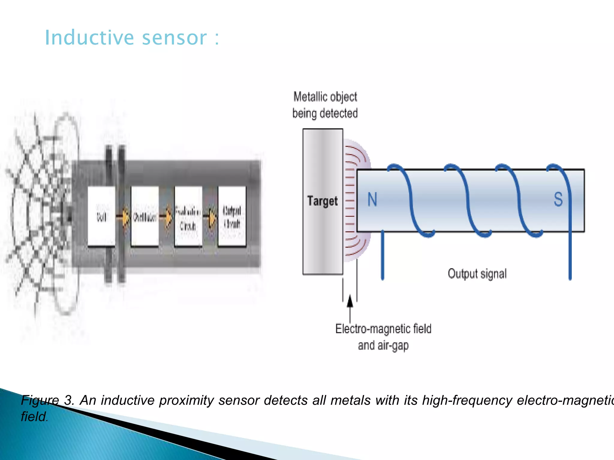
Vehicle Operator Safety
The Advantages of Using
Electronic Sensors in Off-
road Vehicles
 Off-road vehicles are designed to perform
onerous tasks in extreme outdoor conditions. In
industries such as construction, agriculture and
forestry, vehicles must navigate on uneven
surfaces while lifting and moving heavy loads.
For vehicle operators, the chances of tipping or
rolling over are high, and safety is a concern. By
installing preventative measures such as
electronic sensors to detect the vehicle’s
operating condition and alignment, operator
safety is increased. This paper will describe the
advantages of using three distinct sensor types in
off-road vehicles to improve operator safety.
 Summary for 2015/16
 The provisional figure for the number of workers fatally
injured in 2015/16 is 144, and corresponds to a rate of fatal
injury of 0.46 deaths per 100,000 workers.
 The figure of 144 worker deaths in 2015/16 is 7% lower than
the average for the past five years (155). The latest rate of
fatal injury of 0.46 compares to the five-year average rate of
0.52.
 The finalised figure for 2014/15 is 142 worker fatalities, and
corresponds to a rate of 0.46 deaths per 100,000 workers.
 Over the latest 20-year time period there has been a
downward trend in the rate of fatal injury, although in recent
years this shows signs of levelling off.
 There were 67 members of the public fatally injured in
accidents connected to work in 2015/16 (excluding incidents
relating to railways, and those enforced by the Care Quality
Number and rate of fatal injury to workers
1996/97 – 2015/16
How to prevent vehicle operator
injury
To prevent vehicle operator injury, electronic sensors can be used
in off-road vehicles to warn the operator if the vehicle or its load
is in danger. These sensor families include tilt sensors, inductive
position sensors and pressure sensors. The technologies behind
each sensor family will be examined as well as application
examples presented . Environmental exposure is also a safety
factor. As virtual "plants-on-wheels," off-road vehicles are
exposed to extreme shock and vibration, harsh chemicals, dirt
and electrical interference. The sensors used on these vehicles
must be able to withstand these same extreme conditions to
prevent mechanical damage and downtime.
1.Electrolytic Tilt Sensor
2. Micro Electromechanical Sensor (MEMS)
3. Inductive Position Sensors
4. Inductive Proximity Sensors
5. Pressure Sensors
 Tilt Sensors Monitor the Safe Horizontal
Alignment of Vehicles
 Inductive Position Sensors Monitor the
Position of Moving Parts on a Vehicle
 micro electromechanical sensing
 Inductive proximity sensors take advantage
of changes in a resonant circuit c
 Pressure Sensors Monitor a Vehicles Hydraulic
System
The first technology is referred to as electrolytic tilt sensing1.
Sensors filled with electrically conductive liquid are fitted with
two internal measuring cells. By applying an alternating voltage
between the cells’ electrodes, current flows through the liquid
and generates an electrical field. If the sensor tilts, the fluid
surface remains level, so the electrical field changes – as well
as the fluid’s level-dependent resistance. The measuring cells
monitor any change in the liquid’s conductivity and thus detect
angle variations of the X and Y axes with precision. Sensors
using this technology are appropriate for platform leveling
(narrow tilt angle ±15°) or where high precision (0.025°) and a
flexible network connection are advantageous.
Figure 1. Electrolytic tilt sensing technology: measuring cells monitor any change in the liquid’s
conductivity to detect angle variations.
Electrolytic sensor :
The second technology is micro electromechanical sensing (MEMS).
A silicon mass is suspended in the sensor body by two resilient
beams between two stationary capacitor plates. When the body
tilts, the movement is transferred to the beams. The beams deflect
to take the inertial forces of the mass. The deflection changes the
relative position of the mass between two plates. Because each of
the above plates is part of two separate capacitors, the deflection
creates a reciprocal change in capacitance in each of the two. Any
change in capacitance is proportional to the tilt of the sensor,
which then is converted to a change of voltage and transferred as
an analog value to the vehicle controller. Sensors incorporating
this technology are better suited to applications where a single-
axis wide tilt angle (±90°) and lower precision (±1°) are needed.
Figure 2. Micro electromechanical sensing (MEMS) technology: When the vehicle tilts, the movement is
transferred to the beams that deflect to take the inertial forces of the mass. Any change in capacitance is
proportional to the tilt of the sensor.
Inductive position sensors are designed to detect the position of
moving parts on an off-road vehicle. Multiple sensors can be used on
one machine to maximize the operation of the vehicle and to protect
the vehicle’s operator. For example, a position sensor can be used on
an industrial crane’s cable drum to detect the end of its cable,
protecting the crane against machine damage. Position sensors can
also monitor the rotational speed of a gear, detect the position of a
platform, or sense the open- and closed-position of vehicle cab
door. The position sensors provide continual feedback on the
operating condition of the machine’s moving parts and send this
information to the vehicle operator.
 Sensing faces made of UV-resistant plastic that won’t break down from
exposure to sunlight.
 Highly visible LEDs that indicate power and output status that aid in
setup and monitoring, especially in direct sunlight.
 Stainless steel, zero-leak housings encase and protect the electronics
from chemicals and liquid ingress.
 Flexible electronic circuitry that resists the effects of shock and
vibration.
 Long sensing ranges that increase the distance between the target and
sensor and reduce the chance of impact and damage to the sensor.
 Noise-immune technology that enables the sensors to ignore conducted
and radiated electrical noise.
features Position sensors are designed to withstand
outdoor conditions and can include the following:
Position sensor :
Inductive proximity sensors take advantage of changes in a resonant circuit
caused by eddy current losses in conductive materials. An inductive proximity
sensor contains four essential components: a coil of wire wrapped in a ferrite
core, an oscillator circuit, an evaluation circuit, and an output circuit. When
voltage is applied to the sensor, an oscillating current flows through the coil
and radiates an electromagnetic field from the active face of the sensor. This
field is directed and shaped by the ferrite core.
When an electrical conductor or metal target enters the electromagnetic field,
eddy currents are drawn from the oscillator and induced into the target. These
eddy currents draw energy from the electromagnetic field. The losses in
energy caused by the eddy currents are due to the conductivity and
permeability of the target, the distance and position of the target, and the
size and shape of the target.
When the metal target is positioned at a precise distance from the active face
of the sensor, the energy loss caused by the eddy currents becomes so large
that the amplifier cannot output sufficient energy to maintain oscillation and
the magnetic field collapses. The breakdown in oscillation is detected by the
evaluation circuit, which then changes the state of the output circuit.
Figure 3. An inductive proximity sensor detects all metals with its high-frequency electro-magnetic
field.
Inductive sensor :
The hydraulic system of an off-road vehicle is the heart of the
vehicle and is responsible for operating the main controls.
Applications such as loading and unloading, transporting,
lifting, and processing are achieved through the hydraulic
system. Loss in power can result in vehicle downtime and
potential injury to the operator. Pressure sensors can
continuously monitor a vehicle’s hydraulic system and provide
feedback on the system’s operating condition. Pressure sensors
today are stainless steel and compact. The base of the sensor
incorporates a ceramic sensing element that enables over 100
million switching cycles, withstands pressure spikes, and resists
corrosion. The design of the sensing element ensures excellent
repeatability and accuracy across the entire operating range.
Similar to inductive proximity sensors, electronic components
are mounted on flexible film for shock and vibration resistance
up to 1000g.
 IP69K rating for washdown environments
 EMC protection (>100 V/m radiated HF).
 Setpoint, hystersis, delay time and damping
values can be configured to meet specific
application requirements.
Additional design features include :

Presentation on vechile operator safety

  • 1.
    Vehicle Operator Safety TheAdvantages of Using Electronic Sensors in Off- road Vehicles
  • 2.
     Off-road vehiclesare designed to perform onerous tasks in extreme outdoor conditions. In industries such as construction, agriculture and forestry, vehicles must navigate on uneven surfaces while lifting and moving heavy loads. For vehicle operators, the chances of tipping or rolling over are high, and safety is a concern. By installing preventative measures such as electronic sensors to detect the vehicle’s operating condition and alignment, operator safety is increased. This paper will describe the advantages of using three distinct sensor types in off-road vehicles to improve operator safety.
  • 4.
     Summary for2015/16  The provisional figure for the number of workers fatally injured in 2015/16 is 144, and corresponds to a rate of fatal injury of 0.46 deaths per 100,000 workers.  The figure of 144 worker deaths in 2015/16 is 7% lower than the average for the past five years (155). The latest rate of fatal injury of 0.46 compares to the five-year average rate of 0.52.  The finalised figure for 2014/15 is 142 worker fatalities, and corresponds to a rate of 0.46 deaths per 100,000 workers.  Over the latest 20-year time period there has been a downward trend in the rate of fatal injury, although in recent years this shows signs of levelling off.  There were 67 members of the public fatally injured in accidents connected to work in 2015/16 (excluding incidents relating to railways, and those enforced by the Care Quality
  • 5.
    Number and rateof fatal injury to workers 1996/97 – 2015/16
  • 6.
    How to preventvehicle operator injury To prevent vehicle operator injury, electronic sensors can be used in off-road vehicles to warn the operator if the vehicle or its load is in danger. These sensor families include tilt sensors, inductive position sensors and pressure sensors. The technologies behind each sensor family will be examined as well as application examples presented . Environmental exposure is also a safety factor. As virtual "plants-on-wheels," off-road vehicles are exposed to extreme shock and vibration, harsh chemicals, dirt and electrical interference. The sensors used on these vehicles must be able to withstand these same extreme conditions to prevent mechanical damage and downtime.
  • 7.
    1.Electrolytic Tilt Sensor 2.Micro Electromechanical Sensor (MEMS) 3. Inductive Position Sensors 4. Inductive Proximity Sensors 5. Pressure Sensors
  • 8.
     Tilt SensorsMonitor the Safe Horizontal Alignment of Vehicles  Inductive Position Sensors Monitor the Position of Moving Parts on a Vehicle  micro electromechanical sensing  Inductive proximity sensors take advantage of changes in a resonant circuit c  Pressure Sensors Monitor a Vehicles Hydraulic System
  • 9.
    The first technologyis referred to as electrolytic tilt sensing1. Sensors filled with electrically conductive liquid are fitted with two internal measuring cells. By applying an alternating voltage between the cells’ electrodes, current flows through the liquid and generates an electrical field. If the sensor tilts, the fluid surface remains level, so the electrical field changes – as well as the fluid’s level-dependent resistance. The measuring cells monitor any change in the liquid’s conductivity and thus detect angle variations of the X and Y axes with precision. Sensors using this technology are appropriate for platform leveling (narrow tilt angle ±15°) or where high precision (0.025°) and a flexible network connection are advantageous.
  • 10.
    Figure 1. Electrolytictilt sensing technology: measuring cells monitor any change in the liquid’s conductivity to detect angle variations. Electrolytic sensor :
  • 11.
    The second technologyis micro electromechanical sensing (MEMS). A silicon mass is suspended in the sensor body by two resilient beams between two stationary capacitor plates. When the body tilts, the movement is transferred to the beams. The beams deflect to take the inertial forces of the mass. The deflection changes the relative position of the mass between two plates. Because each of the above plates is part of two separate capacitors, the deflection creates a reciprocal change in capacitance in each of the two. Any change in capacitance is proportional to the tilt of the sensor, which then is converted to a change of voltage and transferred as an analog value to the vehicle controller. Sensors incorporating this technology are better suited to applications where a single- axis wide tilt angle (±90°) and lower precision (±1°) are needed.
  • 12.
    Figure 2. Microelectromechanical sensing (MEMS) technology: When the vehicle tilts, the movement is transferred to the beams that deflect to take the inertial forces of the mass. Any change in capacitance is proportional to the tilt of the sensor.
  • 13.
    Inductive position sensorsare designed to detect the position of moving parts on an off-road vehicle. Multiple sensors can be used on one machine to maximize the operation of the vehicle and to protect the vehicle’s operator. For example, a position sensor can be used on an industrial crane’s cable drum to detect the end of its cable, protecting the crane against machine damage. Position sensors can also monitor the rotational speed of a gear, detect the position of a platform, or sense the open- and closed-position of vehicle cab door. The position sensors provide continual feedback on the operating condition of the machine’s moving parts and send this information to the vehicle operator.
  • 14.
     Sensing facesmade of UV-resistant plastic that won’t break down from exposure to sunlight.  Highly visible LEDs that indicate power and output status that aid in setup and monitoring, especially in direct sunlight.  Stainless steel, zero-leak housings encase and protect the electronics from chemicals and liquid ingress.  Flexible electronic circuitry that resists the effects of shock and vibration.  Long sensing ranges that increase the distance between the target and sensor and reduce the chance of impact and damage to the sensor.  Noise-immune technology that enables the sensors to ignore conducted and radiated electrical noise. features Position sensors are designed to withstand outdoor conditions and can include the following:
  • 15.
  • 16.
    Inductive proximity sensorstake advantage of changes in a resonant circuit caused by eddy current losses in conductive materials. An inductive proximity sensor contains four essential components: a coil of wire wrapped in a ferrite core, an oscillator circuit, an evaluation circuit, and an output circuit. When voltage is applied to the sensor, an oscillating current flows through the coil and radiates an electromagnetic field from the active face of the sensor. This field is directed and shaped by the ferrite core. When an electrical conductor or metal target enters the electromagnetic field, eddy currents are drawn from the oscillator and induced into the target. These eddy currents draw energy from the electromagnetic field. The losses in energy caused by the eddy currents are due to the conductivity and permeability of the target, the distance and position of the target, and the size and shape of the target. When the metal target is positioned at a precise distance from the active face of the sensor, the energy loss caused by the eddy currents becomes so large that the amplifier cannot output sufficient energy to maintain oscillation and the magnetic field collapses. The breakdown in oscillation is detected by the evaluation circuit, which then changes the state of the output circuit.
  • 17.
    Figure 3. Aninductive proximity sensor detects all metals with its high-frequency electro-magnetic field. Inductive sensor :
  • 18.
    The hydraulic systemof an off-road vehicle is the heart of the vehicle and is responsible for operating the main controls. Applications such as loading and unloading, transporting, lifting, and processing are achieved through the hydraulic system. Loss in power can result in vehicle downtime and potential injury to the operator. Pressure sensors can continuously monitor a vehicle’s hydraulic system and provide feedback on the system’s operating condition. Pressure sensors today are stainless steel and compact. The base of the sensor incorporates a ceramic sensing element that enables over 100 million switching cycles, withstands pressure spikes, and resists corrosion. The design of the sensing element ensures excellent repeatability and accuracy across the entire operating range. Similar to inductive proximity sensors, electronic components are mounted on flexible film for shock and vibration resistance up to 1000g.
  • 19.
     IP69K ratingfor washdown environments  EMC protection (>100 V/m radiated HF).  Setpoint, hystersis, delay time and damping values can be configured to meet specific application requirements. Additional design features include :

Editor's Notes