Downloaded 999 times
![Fabrication Of Spur
Gear
Supervised by
Md.Golam Kader
Professor,
Md Rasedul Islam
Lecturer,
Department of Mechanical
Engineering, KUET
Course ME 3118
Khulna University Of Engineering & Technology
Department of Mechanical Engineering
Submitted By
Md Rezowan Kabir [1205016]
Md Hasanuzzaman [1205017]
Md Abul Kashem Hemel [1205018]
Md Ashik Mahmud [1205019]
Saikat Biswas [1205020]](https://image.slidesharecdn.com/pre-150726053325-lva1-app6891/85/Presentation-on-Spur-Gear-1-320.jpg)
![Fabrication Of Spur
Gear
Supervised by
Md.Golam Kader
Professor,
Md Rasedul Islam
Lecturer,
Department of Mechanical
Engineering, KUET
Course ME 3118
Khulna University Of Engineering & Technology
Department of Mechanical Engineering
Submitted By
Md Rezowan Kabir [1205016]
Md Hasanuzzaman [1205017]
Md Abul Kashem Hemel [1205018]
Md Ashik Mahmud [1205019]
Saikat Biswas [1205020]](https://image.slidesharecdn.com/pre-150726053325-lva1-app6891/75/Presentation-on-Spur-Gear-1-2048.jpg)
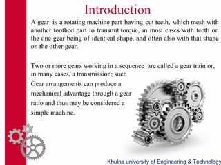
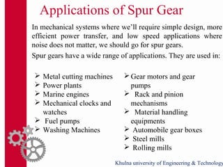
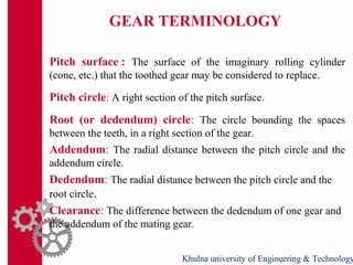
![GEAR TERMINOLOGY(CON’D)
Pressure angle: Pressure angle in relation to gear teeth, also known
as the angle of obliquity, is the angle between the tooth face and the
gear wheel tangent. It is more precisely the angle at a pitch point
between the line of pressure (which is normal to the tooth surface)
and the plane tangent to the pitch surface.
Fig: Pressure angle of spur gear[1]
Khulna university of Engineering & Technology](https://image.slidesharecdn.com/pre-150726053325-lva1-app6891/85/Presentation-on-Spur-Gear-13-320.jpg)
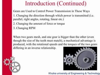
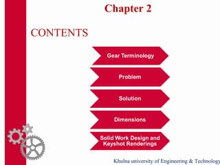
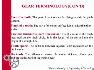
![GEAR TERMINOLOGY
Fig2: Spur gear terminology[2] Fig3: Spur gear terminology[3]](https://image.slidesharecdn.com/pre-150726053325-lva1-app6891/85/Presentation-on-Spur-Gear-14-320.jpg)
![References
[1] FAIRES VIRGIL MORING, “DESIGN OF MACHINE
ELEMENTS”, 4th
edition, The Macmillan Company, New
York/Collier-Macmillan Limited, London
[2] Jain R.K., “ Production Technology”, 16th
edition, 2-B, Nath
Market, Nai Sarak, Delhi-110006
[3]http://www.brighthubengineering.com/manufacturing-
technology/7118-gear-manufacturing-methods
Khulna university of Engineering & TechnologyKhulna university of Engineering & Technology](https://image.slidesharecdn.com/pre-150726053325-lva1-app6891/85/Presentation-on-Spur-Gear-30-320.jpg)


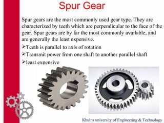
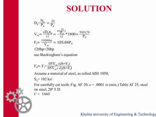
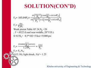
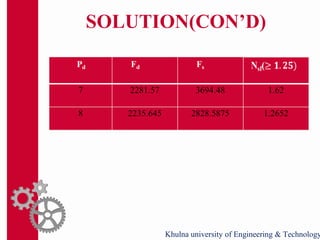
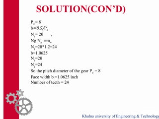
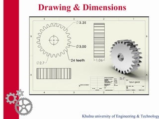
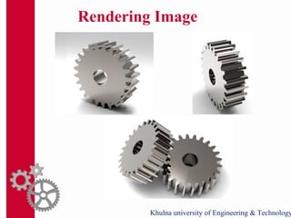
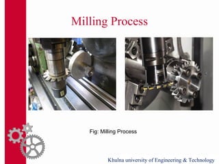
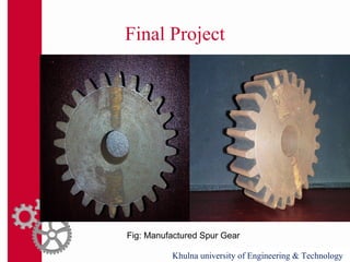
This document discusses the fabrication of a spur gear. It begins with introducing gears and their uses, classifying spur gears and their applications. It then discusses gear terminology and provides examples. The document presents a problem of designing a spur gear to transmit 30hp at 1800rpm. It provides the solution, specifying cast iron material, an 8 pitch diameter, a 1.0625 inch face width, 20 teeth for the pinion and 24 teeth for the gear. Milling is selected as the manufacturing process due to its flexibility, accuracy and cost. Finally, a rendered image of the manufactured spur gear is presented.


