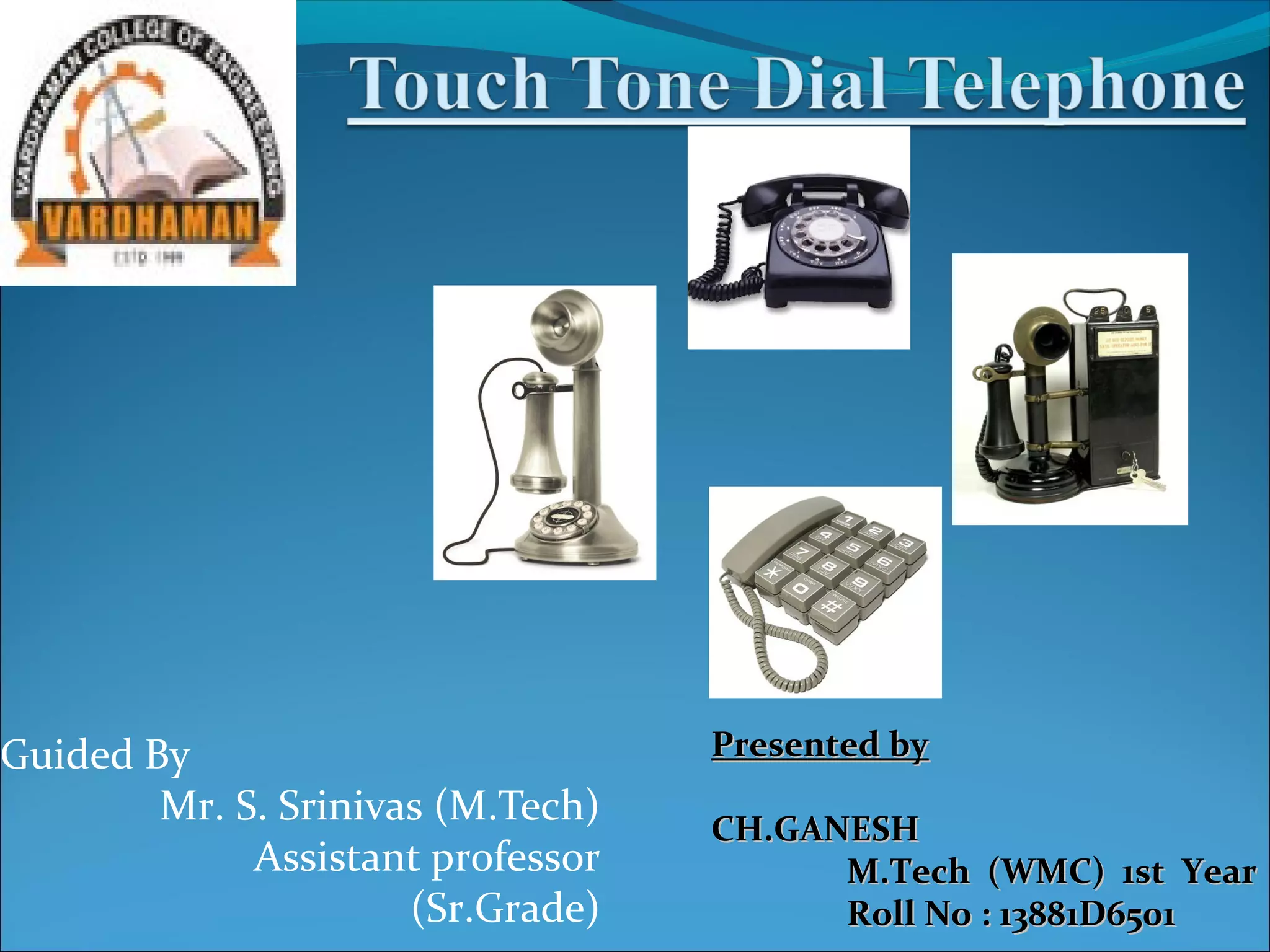
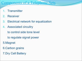
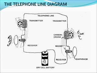
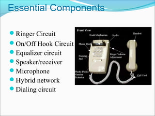
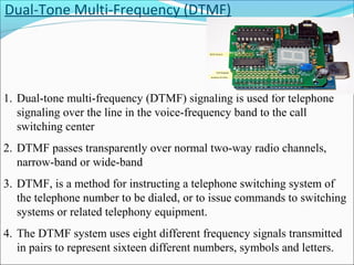
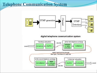
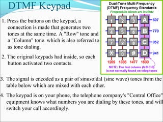
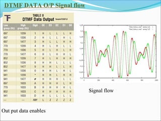
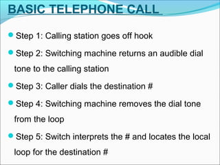
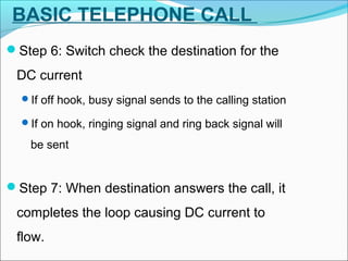
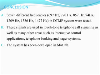
Guided By
Mr. S. Srinivas (M.Tech)
Assistant professor
(Sr.Grade)

Presented by
CH.GANESH
M.Tech (WMC) 1st Year
Roll No : 13881D6501
PRASENTATION OVERVIEW
What is Touch Tone Dial Telephone
Components of Telecommunication set
Essential components
Touch Tone Dial Telephone System
DTMF (Dual-Tone Multi-Frequency )
DTMF Keypad
Basic Telephone call Procedure
Advantages, Applications of Telephone system
Conclusion
References
Components of a Telephone Sets
1. Transmitter
2. Receiver
3. Electrical network for equalization
4. Associated circuitry

to control side tone level
to regulate signal power
5.Magnet
6.Carbon grains
7.Dry Cell Battery
THE TELEPHONE LINE DIAGRAM
Essential Components
Ringer Circuit
On/Off Hook Circuit
Equalizer circuit
Speaker/receiver
Microphone
Hybrid network
Dialing circuit
Touch Tone Dial Telephone
1. The Touch Tone telephone is a communication device that
makes use of a form of telephone.
• The connecting of a call from one phone to another phone that
is known as Dual-Tone Multi-Frequency (DTMF).
• With the rotary dial phones commonly used through the 1970s.
A simple telephone keypad.
• Replaced the rotary dial on the newer touch tone units that
became the industry standard for both cell phones and land
lines.
Dual-Tone Multi-Frequency (DTMF)

1. Dual-tone multi-frequency (DTMF) signaling is used for telephone
signaling over the line in the voice-frequency band to the call
switching center
2. DTMF passes transparently over normal two-way radio channels,
narrow-band or wide-band
3. DTMF, is a method for instructing a telephone switching system of
the telephone number to be dialed, or to issue commands to switching
systems or related telephony equipment.
4. The DTMF system uses eight different frequency signals transmitted
in pairs to represent sixteen different numbers, symbols and letters.
Telephone Communication System
DTMF Keypad
1. Press the buttons on the keypad, a
connection is made that generates two
tones at the same time. A "Row" tone and
a "Column" tone. which is also referred to
as tone dialing.
2. The original keypads had inside, so each
button activated two contacts.
3. The signal is encoded as a pair of sinusoidal (sine wave) tones from the
table below which are mixed with each other.

4. The keypad is on your phone, the telephone company's "Central Office"
equipment knows what numbers you are dialing by these tones, and will
switch your call accordingly.
DTMF DATA O/P Signal flow

Signal flow

Out put data enables
BASIC TELEPHONE CALL
Step 1: Calling station goes off hook
Step 2: Switching machine returns an audible dial

tone to the calling station
Step 3: Caller dials the destination #
Step 4: Switching machine removes the dial tone

from the loop
Step 5: Switch interprets the # and locates the local

loop for the destination #
BASIC TELEPHONE CALL
Step 6: Switch check the destination for the

DC current
If off hook, busy signal sends to the calling station
If on hook, ringing signal and ring back signal will

be sent

Step 7: When destination answers the call, it

completes the loop causing DC current to
flow.
Advantages
1.

Helps to build a healthy relationship.

2.

Being a bridge for people being miles away.

3.

Saves time, money and energy.

4.

Immediate medium to contact one another and
pass urgent messages.

5.

Helps to file complaint against anyone without

identity and save
6.

Gives life for thousands of telemarketers
APPLICATIONS:
Telephone dialing.
 Data entry.
 Credit checking.
 Voice mail system control.
 Electronic mail system.
 Telephone banking system
CONCLUSION:
A. Seven different frequencies (697 Hz, 770 Hz, 852 Hz, 94Hz,

1209 Hz, 1336 Hz, 1477 Hz) in DTMF system were tested.
B. These signals are used in touch-tone telephone call signaling as

well as many other areas such as interactive control
applications, telephone banking and pager systems.
C. The system has been developed in Mat lab.
References
1. J.Bellamy,Digital telephony,2nd edition, John Wiley and sons.
2. Achyut S. God bole, Data communications & Networks, Tata

McGraw hill, India.
3. B.A.Forouzan ,Data Communication & Networking,3rdEdition,

Tata McGraw Hill
Thanking you

Touch Tone Dial Telephone System

  • 1.
    Guided By Mr. S.Srinivas (M.Tech) Assistant professor (Sr.Grade) Presented by CH.GANESH M.Tech (WMC) 1st Year Roll No : 13881D6501
  • 2.
    PRASENTATION OVERVIEW What isTouch Tone Dial Telephone Components of Telecommunication set Essential components Touch Tone Dial Telephone System DTMF (Dual-Tone Multi-Frequency ) DTMF Keypad Basic Telephone call Procedure Advantages, Applications of Telephone system Conclusion References
  • 3.
    Components of aTelephone Sets 1. Transmitter 2. Receiver 3. Electrical network for equalization 4. Associated circuitry to control side tone level to regulate signal power 5.Magnet 6.Carbon grains 7.Dry Cell Battery
  • 4.
  • 5.
    Essential Components Ringer Circuit On/OffHook Circuit Equalizer circuit Speaker/receiver Microphone Hybrid network Dialing circuit
  • 6.
    Touch Tone DialTelephone 1. The Touch Tone telephone is a communication device that makes use of a form of telephone. • The connecting of a call from one phone to another phone that is known as Dual-Tone Multi-Frequency (DTMF). • With the rotary dial phones commonly used through the 1970s. A simple telephone keypad. • Replaced the rotary dial on the newer touch tone units that became the industry standard for both cell phones and land lines.
  • 7.
    Dual-Tone Multi-Frequency (DTMF) 1.Dual-tone multi-frequency (DTMF) signaling is used for telephone signaling over the line in the voice-frequency band to the call switching center 2. DTMF passes transparently over normal two-way radio channels, narrow-band or wide-band 3. DTMF, is a method for instructing a telephone switching system of the telephone number to be dialed, or to issue commands to switching systems or related telephony equipment. 4. The DTMF system uses eight different frequency signals transmitted in pairs to represent sixteen different numbers, symbols and letters.
  • 8.
  • 9.
    DTMF Keypad 1. Pressthe buttons on the keypad, a connection is made that generates two tones at the same time. A "Row" tone and a "Column" tone. which is also referred to as tone dialing. 2. The original keypads had inside, so each button activated two contacts. 3. The signal is encoded as a pair of sinusoidal (sine wave) tones from the table below which are mixed with each other. 4. The keypad is on your phone, the telephone company's "Central Office" equipment knows what numbers you are dialing by these tones, and will switch your call accordingly.
  • 10.
    DTMF DATA O/PSignal flow Signal flow Out put data enables
  • 11.
    BASIC TELEPHONE CALL Step1: Calling station goes off hook Step 2: Switching machine returns an audible dial tone to the calling station Step 3: Caller dials the destination # Step 4: Switching machine removes the dial tone from the loop Step 5: Switch interprets the # and locates the local loop for the destination #
  • 12.
    BASIC TELEPHONE CALL Step6: Switch check the destination for the DC current If off hook, busy signal sends to the calling station If on hook, ringing signal and ring back signal will be sent Step 7: When destination answers the call, it completes the loop causing DC current to flow.
  • 13.
    Advantages 1. Helps to builda healthy relationship. 2. Being a bridge for people being miles away. 3. Saves time, money and energy. 4. Immediate medium to contact one another and pass urgent messages. 5. Helps to file complaint against anyone without identity and save 6. Gives life for thousands of telemarketers
  • 14.
    APPLICATIONS: Telephone dialing.  Dataentry.  Credit checking.  Voice mail system control.  Electronic mail system.  Telephone banking system
  • 15.
    CONCLUSION: A. Seven differentfrequencies (697 Hz, 770 Hz, 852 Hz, 94Hz, 1209 Hz, 1336 Hz, 1477 Hz) in DTMF system were tested. B. These signals are used in touch-tone telephone call signaling as well as many other areas such as interactive control applications, telephone banking and pager systems. C. The system has been developed in Mat lab.
  • 16.
    References 1. J.Bellamy,Digital telephony,2ndedition, John Wiley and sons. 2. Achyut S. God bole, Data communications & Networks, Tata McGraw hill, India. 3. B.A.Forouzan ,Data Communication & Networking,3rdEdition, Tata McGraw Hill
  • 17.