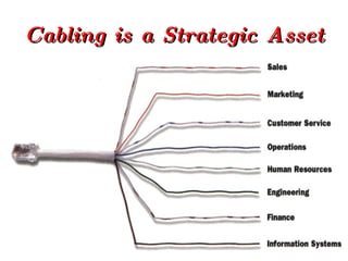
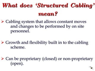
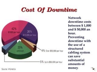
6. Network Investment A cabling system supports and outlives most network components, yet represents only 5% of the total network investment
7. Facilitates Moving Employees Within A Building Moves, adds and changes are inevitable: 40% of employees move within their building every year. These activities can cause serious work-flow disruptions with an unstructured cabling system. A structured cabling system allows moves, adds and changes to occur quickly and cost effectively.
8. Cost Of Downtime Network downtime costs between $ 1,000 and $ 50,000 an hour. Preventing downtime with the use of a structured cabling system can save substantial amounts of money .
25. ISO/IEC/IS-11801 Campus Distributor Building Distributor Floor Distributor Floor Distributor Floor Distributor TO TO Horizontal Cable First Level Backbone Second Level Backbone Transition Point
Two wiring schemes have been adopted. They are nearly identical except that pairs two and three are reversed. T568A is the preferred scheme because it is compatible with 1 or 2 pair USOC systems. Either configuration can be used for Integrated Services Digital Network (ISDN) and high speed data applications. Transmission Categories 3, 4, and 5 are only applicable to this type of pair grouping.
USOC wiring is available in 1, 2, 3 or 4 pair schemes. Pair 1 occupies the centre conductors, pair 2 occupies the next two contacts out, etc. One advantage to this scheme is that a 6 position plug configured with 1, 2 or 3 pairs can be inserted into an 8 position jack and maintain pair continuity. A disadvantage is the poor transmission performance associated with this type of pair sequence. NONE of these pair schemes are cabling standard compliant.
The MMJ is a unique wiring scheme for DEC equipment
A unique wiring scheme for DEC equipment
Asynchronous Transfer Mode (ATM) is an evolving wide and local area network standard for total information transport. ATM is a cell-based packet switching protocol (ISO Layer 2) that is capable of supporting multimedia traffic at very high (gigabit) speeds in the same transmission. ATM runs on fibre-optic or twisted pair media. It offers universal, service independent switching and multiplexing capabilities. 1/. Patch panel 2/. Fibre management system 3/. Optical fibre patch cords 4/. Intelligent hub with ATM Module (customer supplied) 5/. UTP, STP or fibre patch cords 6/. UTP, STP or fibre patching 7/. UTP, STP or fibre cable 8/. Wall plate with modules 9/. UTP, STP or Optical fibre patch cord 10/. Multimedia Workstation
Optical fibre the universal media for high speed / multimedia applications. A variety of protocols are supported namely, FDDI, ATM, Fibre channel and SONET. LOCAL HUB 1/. Fibre management system 2/. Optical fibre patch cord 3/. High speed local LAN hub (customer supplied) 4/. FDDI 62.5 riser rated 6/. Wall outlets 9/. Duplex 62.5 jumper 10/. Workstation (customer supplied) CENTRALISED HUB 1/. Wall mounted splice cabinet 3/. FDDI 62.5 riser rated 4/. Wall outlets 7/. Duplex 62.5 FDDI 8/. Workstation (customer supplied)
Fibre Distributed Data Interface Twisted Pair-Physical Layer Medium Dependant (FDDI-TP-PMD) is a standard developed by ANSI. This protocol, designed to be effective at 155 Mbps over twisted pair, is also known as Copper Distributed Data Interface (CDDI) or Twisted Pair Distributed Data Interface (TPDDI). FMS 1/. Patch Panel 2/. Fibre management system 3/. High speed LAN hub (customer supplied) 4/. UTP, STP CAT 5 patch cord 5/. UTP, STP CAT 5 patch panel 6/. UPT, STP CAT 5 cable 7/. Wall outlets 8/. UTP, STP CAT 5 patch cord 9/. Workstation (customer supplied) Ll-24 1/. Ll-24 Distribution frame 2/. Optical fibre patch cord 3/. High speed LAN hub (customer supplied) 4/. UTP, STP CAT 5 patch cord 5/. UTP, STP CAT 5 patch panel 6/. UPT, STP CAT 5 cable 7/. Wall outlets 8/. UTP, STP CAT 5 patch cord 9/. Workstation (customer supplied)
The IEEE 802.3 100Base-T specification is the standard for Ethernet communications over 100 ohm unshielded twisted pair (UTP) cabling. The IEEE 802.3 10Base-T specification is the standard for Ethernet communications over unshielded twisted pair (UTP) cabling. The EIA 568B wiring sequence is the recommended solution for operation of both 100Base-T and 10Base-T LANs. 100 Base-T / 10 Base-T Modular Interface Hub Cabling 1/. Hub (customer supplied) 2/. UTP, STP CAT 5 patch cord 3/. UTP, STP CAT 5 patch panel 4/. UTP, STP CAT 5 cable 5/. Wall plate 6/. UTP, STP CAT 5 patch cord 7/. Transceiver / Network Interface Card (customer supplied) 8/. Terminal
While category 3 cabling and components will support 10Base-T it is recommended that the use of CAT 5 compliant cable and components will remove the need for future upgrades. 50 Pin Interface Hub Cabling 1/. Hub (customer supplied) 2/. Feeder cable 3/. UTP, STP 10Base-T Patch panel 4/. UTP, STP CAT 5 patch cord 5/. UTP, STP CAT 5 patch panel 6/. UTP, STP CAT 5 cable 7/. Wall outlet 8/. UTP, STP CAT 5 patch cord 9/. Transceiver / Network Interface Card (customer supplied) 10/. Terminal (customer supplied)
The IEEE 802.5 Token Ring is a token passing, base band system where messages are transmitted at a rate of either 4 or 16 Mbps. The data rate of a given ring is determined by the data rates if the workfloor Network Interface Cards (NIC’s). All NIC’s on a given Token Ring MUST operate at the same speed (4 or 16 Mbps). A Multi-floor Access Unit (MAU) or cabling concentrator is used to create a star wired ring topology. EIA 568A Token Ring Cabling 1/. Token Ring MAU 2/. UTP, STP CAT 5 patch cord 3/. UTP, STP CAT 5 patch panel 4/. UTP, STP CAT 5 cable 5/. Wall outlet 6/. UTP, STP CAT 5 patch cord 7/. Token ring media filter (4 or 16 Mbps) 8/. Terminal
This solution converts an IBM twin-axial interface for operation over a single unshielded twisted pair cable using a balun. In addition, the bus wiring architecture of the IBM system is utilised. An IBM representative should be consulted to determine the maximum number of 5291 devices that can be supported by each controller. 1/. AS400 Controller 2/. Twinax balun 3/. UTP, STP CAT 5 patch cord 4/. Passive hub 5/. UTP, STP CAT 5 patch cord 6/. UTP, STP CAT 5 patch panel 7/. UTP, STP CAT 5 cable 8/. Wall plate 9/. UTP, STP CAT 5 patch cord 10/. Twinax balun 11/. Terminal
IBM 3270 type A devices were designed with RG62A/U coaxial cable interfaces communicating at the rate of 2.35 Mbps. A 3270 balun will impedance match the interface and convert the signal for operation over unshielded twisted pair cable, a lower cost and easier to install media. 1/. 3270 Controller 2/. 3270 balun 3/. 16 channel, 2 wire UTP, STP Octopus 4/. UTP, STP feeder cable 5/. UTP, STP patch panel 6/. UTP, STP CAT 5 patch cord 7/. UTP, STP CAT 5 patch panel 8/. UTP, STP CAT 5 cable 9/. Wall outlet 10/. UTP, STP CAT 5 patch cord 11/. 3270 balun 12/. Terminal
The EIA RS232 standard was developed to allow the attachment of data communications equipment (DCE - modem, mux, data switch) to data terminal equipment (DTE - computer, terminal or printer) over a 25 wire cable wired straight through or point to point. The interface connector is a 25 pin D type connector. 1/. Controller 2/. UTP, STP 25 pin adapter 3/. 6 channel, 8 wire UTP, STP Octopus 4/. UTP, STP feeder cable 5/. UTP, STP patch panel 6/. UTP, STP patch lead 7/. UTP, STP CAT 5 patch panel 8/. UTP, STP CAT 5 cable 9/. Wall outlet 10/. UTP, STP patch cord 11/. UTP, STP 25 pin adapter 12/. Terminal
Terminal servers provide a cost effective, flexible way to connect terminals to a host in an 802.3 Ethernet LAN. They provide high density service and significant savings in cabling and installation. Terminal servers handle asynchronous communications at speeds up to 38.4 Kbps. 1/. Terminal Server 2/. UTP, STP 25 pin adapter 3/. 8 channel, 6 wire UTP, STP Octopus 4/. UTP, STP feeder cable 5/. UTP, STP patch panel 6/. UTP, STP patch lead 7/. UTP, STP CAT 5 patch panel 8/. UTP, STP CAT 5 cable 9/. Wall outlet 10/. UTP, STP patch cord 11/. UTP, STP 25 pin adapter 12/. Terminal