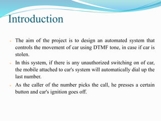
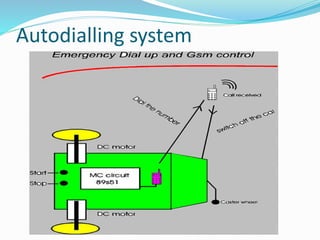
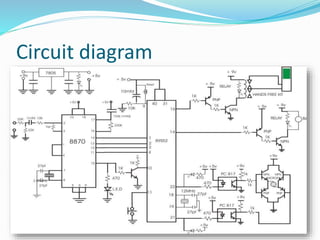
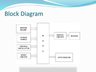
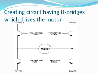
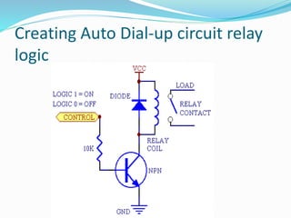
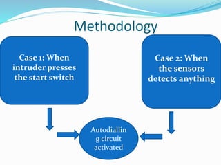
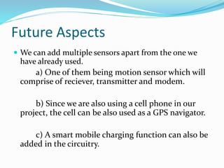
Submitted by-
Devna Sharma (176)
Durgesh Baranwal (179)
Mohit Arora (216)
Nishtha Sharma (229)
Mentor:
Dr. Pradeep Kumar Rana
Introduction
 The aim of the project is to design an automated system that
controls the movement of car using DTMF tone, in case if car is
stolen.
 In this system, if there is any unauthorized switching on of car,
the mobile attached to car's system will automatically dial up the
last number.
 As the caller of the number picks the call, he presses a certain
button and car's ignition goes off.
Autodialling system
Circuit diagram
Block Diagram
Components used
 IC 8870 DTMF Decoder
 IC 89S52 ( 40 PIN controller)
 Relay -9 VOLT
 SAMSUNG Mobilephone Handsfree Kit
 PCB General
 Crystal 3.58 MHz(1)
 Crystal 12 MHz (1)
 Optocoupler PC 817 (2)
 NPN Transistor BC 548(4)
Components used
 PNP Transistor BC 558 (3)
 Capacitor:10 mfd (1) 1000mfd (2)0.1(104) mfd
 Gas Sensor
 Thermal Sensor
 Piezo Sensor (4)
 Push to on switch (2)
 led (1)
 Buzzer(1)
 Resistor:22K OHM (2), 470 OHM (4), 1K (6)
AC supply
 In addition to the full wave rectifier circuit ,we
have added, a voltage regulator to maintain the
output voltage at 5V.
 the capacitor(uf) nullifes the effect of the
voltage regulator.
DTMF decoder
DTMF keypad frequencies (with sound
clips)
1209
Hz
1336 H
z
1477 H
z
1633 H
z
697 H
z
1 2 3 A
770 H
z
4 5 6 B
852 H
z
7 8 9 C
941 H
z
* 0 # D
DTMF Decoder
 Dual-tone multi-frequency signaling (DTMF) is used for
telecommunication signaling over analog telephone lines in
the voice-frequency band
 The DTMF system uses eight different frequency signals
transmitted in pairs to represent sixteen different numbers,
symbols and letters
 The DTMF keypad is laid out in a 4×4 matrix.
 DTMF is basically a signal to the phone company that you
generate when you press an ordinary telephone's touch keys
Creating circuit having H-bridges
which drives the motor.
 To control a movement of the dc motor we require a H
bridge circuit.
 H bridge is a combination of the 4 transistor circuit.
 Two transistor’s are npn and two transistor’s are pnp
transistor.
 With the help of this four transistor circuit we control
the movement of the motor automatically.
Creating circuit having H-bridges
which drives the motor.
Creating Auto Dial-up circuit relay
logic .
 Using this relay logic,handsfree redials the last
number store in the mobile.
 Relay logic is used for the autodialup circuit.
 we connect a one relay coil with the controller with two
transistor circuit.
Creating Auto Dial-up circuit relay
logic
Methodology
Case 1: When
intruder presses
the start switch
Case 2: When
the sensors
detects anything
Autodiallin
g circuit
activated
Proposed Plan
• 1st-2nd weeks – Literature Survey
• 3rd week – Component study
• 4th week – Procuring Component
• 5th-6th week – Study of embedded language
• 7th week – Circuit design
• 8th week – circuit implementation and corrections (if any)
• 9th -10th week – Microcontroller Programming
• 11th-12th week – Hardware implementation
• 13th-14th week – Final project report, model and presentation
submission
Future Aspects
 We can add multiple sensors apart from the one we
have already used.
a) One of them being motion sensor which will
comprise of reciever, transmitter and modem.
b) Since we are also using a cell phone in our
project, the cell can be also used as a GPS navigator.
c) A smart mobile charging function can also be
added in the circuitry.
REFERENCES
 http://www.atmel.com/dyn/resources/prod_documents/doc2487.pdf - for
details of 8951 MC
 http://www.keil.com/dd/docs/datashts/atmel/at_c51ism.pdf - instruction set
of atmel 89s
 http://www.pcbased.in/8051-microcontrollers/89s51-architecture-instruction-
set-tutorials--89S51-microcontrollers.asp - PIN DESCRIPTION OF 89S51
 http://www.siongboon.com/projects/2005-07-18_dtmf_circuits/ - for dtmf ic
8870
 http://www.digchip.com/datasheets/download_datasheet.php?id=541970&par
t-number=M-8870 - for studying 8870
 http://www.freewebs.com/maheshwankhede/dtmfdecoder.html - interfacing
8051 with dtmf decoder
 http://www.societyofrobots.com/robotforum/index.php?topic=4786.0 - forum
on robotics discusing dtmf use
 www.tech-faq.com/dtmf.html - studying dtmf
 http://www.intlsensor.com/fumigation.html - gas sensor
 http://www.doctronics.co.uk/555.htm
Final_Year_Project_Mohit

Final_Year_Project_Mohit

  • 1.
    Submitted by- Devna Sharma(176) Durgesh Baranwal (179) Mohit Arora (216) Nishtha Sharma (229) Mentor: Dr. Pradeep Kumar Rana
  • 2.
    Introduction  The aimof the project is to design an automated system that controls the movement of car using DTMF tone, in case if car is stolen.  In this system, if there is any unauthorized switching on of car, the mobile attached to car's system will automatically dial up the last number.  As the caller of the number picks the call, he presses a certain button and car's ignition goes off.
  • 3.
  • 4.
  • 5.
  • 6.
    Components used  IC8870 DTMF Decoder  IC 89S52 ( 40 PIN controller)  Relay -9 VOLT  SAMSUNG Mobilephone Handsfree Kit  PCB General  Crystal 3.58 MHz(1)  Crystal 12 MHz (1)  Optocoupler PC 817 (2)  NPN Transistor BC 548(4)
  • 7.
    Components used  PNPTransistor BC 558 (3)  Capacitor:10 mfd (1) 1000mfd (2)0.1(104) mfd  Gas Sensor  Thermal Sensor  Piezo Sensor (4)  Push to on switch (2)  led (1)  Buzzer(1)  Resistor:22K OHM (2), 470 OHM (4), 1K (6)
  • 8.
  • 9.
     In additionto the full wave rectifier circuit ,we have added, a voltage regulator to maintain the output voltage at 5V.  the capacitor(uf) nullifes the effect of the voltage regulator.
  • 10.
    DTMF decoder DTMF keypadfrequencies (with sound clips) 1209 Hz 1336 H z 1477 H z 1633 H z 697 H z 1 2 3 A 770 H z 4 5 6 B 852 H z 7 8 9 C 941 H z * 0 # D
  • 11.
    DTMF Decoder  Dual-tonemulti-frequency signaling (DTMF) is used for telecommunication signaling over analog telephone lines in the voice-frequency band  The DTMF system uses eight different frequency signals transmitted in pairs to represent sixteen different numbers, symbols and letters  The DTMF keypad is laid out in a 4×4 matrix.  DTMF is basically a signal to the phone company that you generate when you press an ordinary telephone's touch keys
  • 12.
    Creating circuit havingH-bridges which drives the motor.  To control a movement of the dc motor we require a H bridge circuit.  H bridge is a combination of the 4 transistor circuit.  Two transistor’s are npn and two transistor’s are pnp transistor.  With the help of this four transistor circuit we control the movement of the motor automatically.
  • 13.
    Creating circuit havingH-bridges which drives the motor.
  • 14.
    Creating Auto Dial-upcircuit relay logic .  Using this relay logic,handsfree redials the last number store in the mobile.  Relay logic is used for the autodialup circuit.  we connect a one relay coil with the controller with two transistor circuit.
  • 15.
    Creating Auto Dial-upcircuit relay logic
  • 16.
    Methodology Case 1: When intruderpresses the start switch Case 2: When the sensors detects anything Autodiallin g circuit activated
  • 17.
    Proposed Plan • 1st-2ndweeks – Literature Survey • 3rd week – Component study • 4th week – Procuring Component • 5th-6th week – Study of embedded language • 7th week – Circuit design • 8th week – circuit implementation and corrections (if any) • 9th -10th week – Microcontroller Programming • 11th-12th week – Hardware implementation • 13th-14th week – Final project report, model and presentation submission
  • 18.
    Future Aspects  Wecan add multiple sensors apart from the one we have already used. a) One of them being motion sensor which will comprise of reciever, transmitter and modem. b) Since we are also using a cell phone in our project, the cell can be also used as a GPS navigator. c) A smart mobile charging function can also be added in the circuitry.
  • 19.
    REFERENCES  http://www.atmel.com/dyn/resources/prod_documents/doc2487.pdf -for details of 8951 MC  http://www.keil.com/dd/docs/datashts/atmel/at_c51ism.pdf - instruction set of atmel 89s  http://www.pcbased.in/8051-microcontrollers/89s51-architecture-instruction- set-tutorials--89S51-microcontrollers.asp - PIN DESCRIPTION OF 89S51  http://www.siongboon.com/projects/2005-07-18_dtmf_circuits/ - for dtmf ic 8870  http://www.digchip.com/datasheets/download_datasheet.php?id=541970&par t-number=M-8870 - for studying 8870  http://www.freewebs.com/maheshwankhede/dtmfdecoder.html - interfacing 8051 with dtmf decoder  http://www.societyofrobots.com/robotforum/index.php?topic=4786.0 - forum on robotics discusing dtmf use  www.tech-faq.com/dtmf.html - studying dtmf  http://www.intlsensor.com/fumigation.html - gas sensor  http://www.doctronics.co.uk/555.htm