SlideShare a Scribd company logo
1
Project Report
ON
DTMF Based Mobile Controlled Robot
Submitted In Partial Fulfillment of the Requirements for the
Diploma of Electronics and Telecommunication Engineering By
Mr. Pankaj Rai
Under the guidance of
Ms. Meenal Vatsaraj
DEPARTMENT OF ELECTRONICS AND TELECOMMUNICATION ENGINEERING
(DIPLOMA)
ARMIET
Alamuri Ratnamala Institute of Engineering and Technology
(Run by Koti Vidya Charitable Trust)
A.S. Rao Nagar, Sapgaon, Tal Shahapur, Dist Thane-421601
2
Alamuri Ratnamala Institute of Engineering and Technology
(Run by Koti Vidya Charitable Trust)
A.S. Rao Nagar, Sapgaon, Tal Shahapur, Dist Thane-421601
Project Report Submitted By
Name: Mr. Pankaj Rai.
Title of project: DTMF BASED MOBILECONTROLLED ROBOT
Guide Name: Ms. Meenal Vatsaraj
Ms. Meenal Vatsaraj Mr. C. Nagababu Mr. C. Nagababu
(Project Guide) (H.O.D.) (Principal)
3
CERTIFICATE
This is to certify that Mr. Pankaj Shivchander Rai of PIN
ARMIET/DIP/ET-14 RP 217 has delivered a project report for the
Project Topic “DTMF Based Mobile Controlled Robot” and
submitted report in the “Alamuri Ratnamala Institute of Engineering
and Technology”, Sapgaon, Tal Shahapur, Dist, Thane, in the partial
fulfillment of the diploma of “Electronics and telecommunication
Engineering” from MSBTE for the year 2015-16
Guide H.O.D. Principal
Meenal Vatsaraj Nagababu Chekuri Nagababu Chekuri
4
Acknowledgement
I would like to acknowledge and extend our heartfelt gratitude to all those people who have been
associated with this project and have helped us with it thus making it a worthwhile experience.
Firstly I extend our thanks to various people which include my project Guide Ms. Meenal Vatsaraj, my
H.O.D. Nagababu Chekuri, who have shared their opinions and experiences through which I received
the required information for my report. I am also thankful to all the staff members of EXTC Dept. for
their highly cooperative and encouraging attitudes, which have always boosted me.
I also take this opportunity with great pleasure to thank our Honorable Founder Trustee A.V. Gupta,
Honorable Alternate Chairman Dr. L.S. Bothra and Principal Prof. Nagababu Chekuri whose timely
support and encouragement has helped us succeeds in our venture.
Pankaj Rai
5
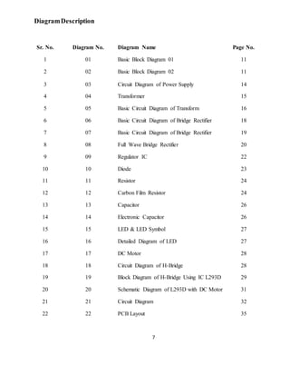
INDEX
Sr. No. Topic Name Page No.
1 Abstract 08
2 Introduction 09
3 Block Diagram 11
4 Explanation Of Block Diagram 12
5 Hardware Description 14
a) Power Supply 14
b) Transformer 15
i. Basic Parts Of Transformer 16
ii. Components Of Transformer 17
c) Bridge Rectifier 18
i. Basic Operation 18
ii. Output Smoothing 20
d) Regulator IC 22
e) Diode 23
f) Resistor 24
g) Capacitor 26
h) LED 27
i) DC Motor 28
6 Circuit Diagram 32
7 Explanation of Circuit Diagram 33
8 PCB Layout 35
9 Component List 36
10 Final Testing 37
11 Application 38
12 Future Scope 40
13 Conclusion 42
14 Reference 43
6
Table Description
Sr. No. Table No. Table Name Page No.
1 01 Truth Table 30
2 02 DTMF Tone Assignment System 34
7
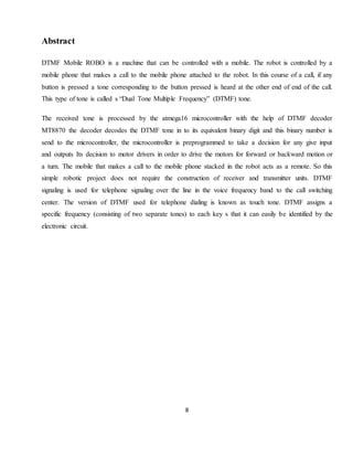
DiagramDescription
Sr. No. Diagram No. Diagram Name Page No.
1 01 Basic Block Diagram 01 11
2 02 Basic Block Diagram 02 11
3 03 Circuit Diagram of Power Supply 14
4 04 Transformer 15
5 05 Basic Circuit Diagram of Transform 16
6 06 Basic Circuit Diagram of Bridge Rectifier 18
7 07 Basic Circuit Diagram of Bridge Rectifier 19
8 08 Full Wave Bridge Rectifier 20
9 09 Regulator IC 22
10 10 Diode 23
11 11 Resistor 24
12 12 Carbon Film Resistor 24
13 13 Capacitor 26
14 14 Electronic Capacitor 26
15 15 LED & LED Symbol 27
16 16 Detailed Diagram of LED 27
17 17 DC Motor 28
18 18 Circuit Diagram of H-Bridge 28
19 19 Block Diagram of H-Bridge Using IC L293D 29
20 20 Schematic Diagram of L293D with DC Motor 31
21 21 Circuit Diagram 32
22 22 PCB Layout 35
8
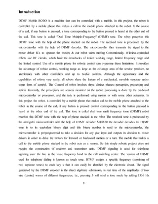
Abstract
DTMF Mobile ROBO is a machine that can be controlled with a mobile. The robot is controlled by a
mobile phone that makes a call to the mobile phone attached to the robot. In this course of a call, if any
button is pressed a tone corresponding to the button pressed is heard at the other end of end of the call.
This type of tone is called s “Dual Tone Multiple Frequency” (DTMF) tone.
The received tone is processed by the atmega16 microcontroller with the help of DTMF decoder
MT8870 the decoder decodes the DTMF tone in to its equivalent binary digit and this binary number is
send to the microcontroller, the microcontroller is preprogrammed to take a decision for any give input
and outputs Its decision to motor drivers in order to drive the motors for forward or backward motion or
a turn. The mobile that makes a call to the mobile phone stacked in the robot acts as a remote. So this
simple robotic project does not require the construction of receiver and transmitter units. DTMF
signaling is used for telephone signaling over the line in the voice frequency band to the call switching
center. The version of DTMF used for telephone dialing is known as touch tone. DTMF assigns a
specific frequency (consisting of two separate tones) to each key s that it can easily be identified by the
electronic circuit.
9
Introduction
DTMF Mobile ROBO is a machine that can be controlled with a mobile. In this project, the robot is
controlled by a mobile phone that makes a call to the mobile phone attached to the robot. In the course
of a call, if any button is pressed, a tone corresponding to the button pressed is heard at the other end of
the call. This tone is called "Dual Tone Multiple-Frequency" (DTMF) tone. The robot perceives this
DTMF tone with the help of the phone stacked on the robot. The received tone is processed by the
microcontroller with the help of DTMF decoder. The microcontroller then transmits the signal to the
motor driver ICs to operate the motors & our robot starts moving Conventionally, Wireless-controlled
robots use RF circuits, which have the drawbacks of limited working range, limited frequency range and
the limited control. Use of a mobile phone for robotic control can overcome these limitations. It provides
the advantage of robust control, working range as large as the coverage area of the service provider, no
interference with other controllers and up to twelve controls. Although the appearance and the
capabilities of robots vary vastly, all robots share the feature of a mechanical, movable structure under
some form of control. The Control of robot involves three distinct phases: perception, processing and
action. Generally, the preceptors are sensors mounted on the robot, processing is done by the on-board
microcontroller or processor, and the task is performed using motors or with some other actuators. In
this project the robot, is controlled by a mobile phone that makes call to the mobile phone attached to the
robot in the course of the call, if any button is pressed control corresponding to the button pressed is
heard at the other end of the call. This tone is called dual tone multi frequency tome (DTMF) robot
receives this DTMF tone with the help of phone stacked in the robot The received tone is processed by
the atmega16 microcontroller with the help of DTMF decoder MT8870 the decoder decodes the DTMF
tone in to its equivalent binary digit and this binary number is send to the microcontroller, the
microcontroller is preprogrammed to take a decision for any give input and outputs its decision to motor
drivers in order to drive the motors for forward or backward motion or a turn. The mobile that makes a
call to the mobile phone stacked in the robot acts as a remote. So this simple robotic project does not
require the construction of receiver and transmitter units. DTMF signaling is used for telephone
signaling over the line in the voice frequency band to the call switching center. The version of DTMF
used for telephone dialing is known as touch tone. DTMF assigns a specific frequency (consisting of
two separate tones) to each key s that it can easily be identified by the electronic circuit. The signal
generated by the DTMF encoder is the direct algebraic submission, in real time of the amplitudes of two
sine (cosine) waves of different frequencies, i.e., pressing 5 will send a tone made by adding 1336 Hz
10
and 770 Hz to the other end of the mobile. The important components of this robot are DTMF decoder,
Microcontroller and motor driver. An MT8870 series DTMF decoder is used here. All types of the
mt8870 series use digital counting techniques to detect and decode all the sixteen DTMF tone pairs in to
a four bit code output. The built -in dial tone rejection circuit eliminated the need for pre- filtering.
When the input signal given at pin2 (IN-) single ended input configuration is recognized to be effective,
the correct four bit decode signal of the DTMF tone is transferred to Q1 (pin11) through Q4(pin14)
outputs
11
Block Diagram
Fig No.01 Basic Block Diagram 01
Fig No.02 Basic Block Diagram 02
L293D
POWER SUPPLY
TELEPHONE
DTMF
DECODER
MOTOR
8051
MICROCONTR
OLLER
MOTOR
12
Explanation of Block Diagram
Cellphone
Cellphone is the basic input device of this project. Cellphone is used to give the input to the
DTMF decoder. It uses RF signal to communicate with DTMF decoder.
DTMF Decoder
Today, most telephone equipment use a DTMF receiver IC. One common DTMF
receiver IC is the Motorola MT8870 that is widely used in electronic communications circuits.
The MT8870 is an 18-pin IC. It is used in telephones and a variety of other applications. When
a proper output is not obtained in projects using this IC, engineers or technicians need to test
this IC separately. A quick testing of this IC could save a lot of time in re-search labs and
manufacturing industries of communication instruments. Here’s a small and handy tester
circuit for the DTMF IC. It can be assembled on a multipurpose PCB with an 18-pin IC base.
One can also test the IC on a simple breadboard.
For optimum working of telephone equipment, the DTMF receiver must be designed to
recognize a valid tone pair greater than 40 ms in duration and to accept successive digit tone-
pairs that are greater than 40 ms apart. However, for other applications like remote controls and
radio communications, the tone duration may differ due to noise considerations. Therefore, by
adding an extra resistor and steering diode the tone duration can be set to different values. The
circuit is configured in balanced-line mode. To reject common-mode noise signals, a balanced
differential amplifier input is used. The circuit also provides an excellent bridging interface
across a properly terminated telephone line. Transient protection may be achieved by splitting
the input resistors and inserting ZENER diodes (ZD1 and ZD2) to achieve voltage clamping.
This allows the transient energy to be dissipated in the resistors and diodes, and limits the
maximum voltage that may appear at the inputs. Whenever you press any key on your local
telephone keypad, the delayed steering (Std) output of the IC goes high on receiving the tone-
pair, causing LED5 (connected to pin 15 of IC via resistor R15) to glow. It will be high for a
duration depending on the values of capacitor and resistors at pins 16 and 17. The optional
circuit shown within dot-ted line is used for guard time adjustment. The LEDs connected via
resistors R11 to R14 at pins 11 through 14, respectively, indicate the output of the IC. The
tone-pair DTMF (dual-tone multi-frequency) generated by pressing the telephone button is
13
converted into bi-nary values internally in the IC. The binary values are indicated by glowing
of LEDs at the output pins of the IC. LED1 represents the lowest significant bit (LSB) and
LED4 represents the most significant bit (MSB). So, when you dial a number, say, 5, LED1
and LED3 will glow, which is equal to 0101. Similarly, for every other number dialed on your
telephone, the corresponding LEDs will glow. Thus, a non-defective IC should indicate proper
bi-nary values corresponding to the decimal number pressed on your telephone key-pad. To
test the DTMF IC 8870/KT3170, proceed as follows:
• Connect local telephone and the circuit in parallel to the same telephone line.
• Switch on S1. (Switch on auxiliary switch S2 only if keys A, B, C, and D are to be
used.)
• Now push key ‘*’ to generate DTMF tone.
• Push any decimal key from the telephone keypad. Observe the equivalent binary as
shown in the table.
• If the binary number implied by glowing of LED1 to LED4 is equivalent to the
pressed key number (decimal/A, B, C, or D), the DTMF IC 8870 is correct.
Keys A, B, C, and D on the telephone keypad are used for special signaling and are not available on
standard pushbutton telephone keypads. Pin 5 of the IC is pulled down to ground through resistor R8.
Switch on auxiliary switch S2. Now the high logic at pin 5 enables the detection of tones representing
characters A, B, C, and D.
Microcontroller
The AT89C2051 is a low-voltage, high-performance CMOS 8-bit microcomputer with 2K
bytes of Flash programmable and erasable read-only memory (PEROM). The device is manufactured
using Atmel’s high-density nonvolatile memory technology and is compatible with the industry-standard
MCS-51 instruction set. By combining a versatile 8-bit CPU with Flash on a monolithic chip, the Atmel
AT89C2051 is a powerful microcomputer which provides a highly-flexible and cost-effective solution to
many embedded control applications.
Motor Driver
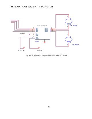
The L293D is a quad, high-current, half-H driver designed to provide bidirectional drive currents of up
to 600 mA at voltages from 4.5V to 36V. It makes it easier to drive the DC motors. The L293D consists
of four drivers. Pins INI through IN4 and OUT1 through OUT4 are input and output pins, respectively,
of driver 1 through driver 4. Drivers 1 and 2, and drivers 3 and 4 are enabled by enable pin 1 (EN1) and
pin 9 (EN2) respectively. When enable input EN1 (pin 1) is high, drivers 1 and 2 are enabled and the
outputs corresponding to their inputs are active. Similarly, enable input EN2 (pin 9) enables drivers 3
and 4.
14
Hardware Description
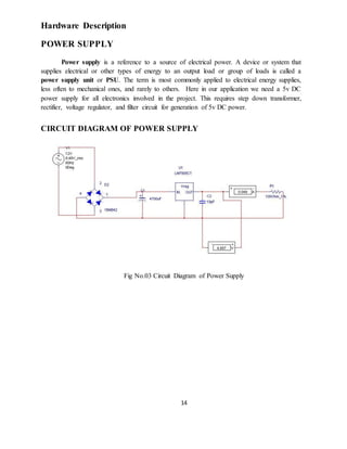
POWER SUPPLY
Power supply is a reference to a source of electrical power. A device or system that
supplies electrical or other types of energy to an output load or group of loads is called a
power supply unit or PSU. The term is most commonly applied to electrical energy supplies,
less often to mechanical ones, and rarely to others. Here in our application we need a 5v DC
power supply for all electronics involved in the project. This requires step down transformer,
rectifier, voltage regulator, and filter circuit for generation of 5v DC power.
CIRCUIT DIAGRAM OF POWER SUPPLY
Fig No.03 Circuit Diagram of Power Supply
15
TRANSFORMER
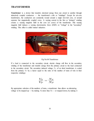
Transformer is a device that transfers electrical energy from one circuit to another through
inductively coupled conductors — the transformer's coils or "windings". Except for air-core
transformers, the conductors are commonly wound around a single iron-rich core, or around
separate but magnetically coupled cores. A varying current in the first or "primary" winding
creates a varying magnetic field in the core (or cores) of the transformer. This varying
magnetic field induces a varying electromotive force (EMF) or "voltage" in the "secondary"
winding. This effect is called mutual induction.
Fig No.04 Transformer
If a load is connected to the secondary circuit, electric charge will flow in the secondary
winding of the transformer and transfer energy from the primary circuit to the load connected
in the secondary circuit. The secondary induced voltage VS, of an ideal transformer, is scaled
from the primary VP by a factor equal to the ratio of the number of turns of wire in their
respective windings:
By appropriate selection of the numbers of turns, a transformer thus allows an alternating
voltage to be stepped up — by making NS more than NP — or stepped down, by making it
16
BASIC PARTS OF A TRANSFORMER
In its most basic form a transformer consists of:
• A primary coil or winding.
• A secondary coil or winding.
• A core that supports the coils or windings.
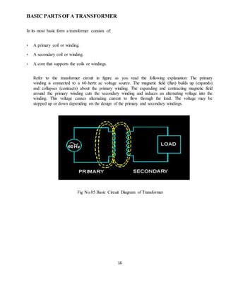
Refer to the transformer circuit in figure as you read the following explanation: The primary
winding is connected to a 60-hertz ac voltage source. The magnetic field (flux) builds up (expands)
and collapses (contracts) about the primary winding. The expanding and contracting magnetic field
around the primary winding cuts the secondary winding and induces an alternating voltage into the
winding. This voltage causes alternating current to flow through the load. The voltage may be
stepped up or down depending on the design of the primary and secondary windings.
Fig No.05 Basic Circuit Diagram of Transformer
17
THE COMPONENTSOF A TRANSFORMER
Two coils of wire (called windings) are wound on some type of core material. In some cases
the coils of wire are wound on a cylindrical or rectangular cardboard form. In effect, the core
material is air and the transformer is called an AIR-CORE TRANSFORMER. Transformers
used at low frequencies, such as 60 hertz and 400 hertz, require a core of low-reluctance
magnetic material, usually iron. This type of transformer is called an IRON-CORE
TRANSFORMER. Most power transformers are of the iron-core type. The principle parts of a
transformer and their functions are:
• The CORE, which provides a path for the magnetic lines of flux.
• The PRIMARY WINDING, which receives energy from the ac source.
• The SECONDARY WINDING, which receives energy from the primary winding and delivers it to
the load.
• The ENCLOSURE, which protects the above components from dirt, moisture, and mechanical
damage.
18
BRIDGE RECTIFIER
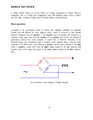
A bridge rectifier makes use of four diodes in a bridge arrangement to achieve full-wave
rectification. This is a widely used configuration, both with individual diodes wired as shown
and with single component bridges where the diode bridge is wired internally.
Basic operation
According to the conventional model of current flow originally established by Benjamin
Franklin and still followed by most engineers today, current is assumed to flow through
electrical conductors from the positive to the negative pole. In actuality, free electrons in a
conductor nearly always flow from the negative to the positive pole. In the vast majority of
applications, however, the actual direction of current flow is irrelevant. Therefore, in the
discussion below the conventional model is retained. In the diagrams below, when the input
connected to the left corner of the diamond is positive, and the input connected to the right
corner is negative, current flows from the upper supply terminal to the right along the red
(positive) path to the output, and returns to the lower supply terminal via the blue (negative)
path.
Fig No.06 Basic Circuit Diagram of Bridge Rectifier
19
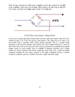
When the input connected to the left corner is negative, and the input connected to the right
corner is positive, current flows from the lower supply terminal to the right along the red path
to the output, and returns to the upper supply terminal via the blue path.
Fig No.07 Basic Circuit Diagram of Bridge Rectifier
In each case, the upper right output remains positive and lower right output negative. Since this is true
whether the input is AC or DC, this circuit not only produces a DC output from an AC input, it can
also provide what is sometimes called "reverse polarity protection". That is, it permits normal
functioning of DC-powered equipment when batteries have been installed backwards, or when the
leads (wires) from a DC power source have been reversed, and protects the equipment from potential
damage caused by reverse polarity. Prior to availability of integrated electronics, such a bridge
rectifier was always constructed from discrete components. Since about 1950, a single four-terminal
component containing the four diodes connected in the bridge configuration became a standard
commercial component and is now available with various voltage and current ratings.
20
OUTPUT SMOOTHING
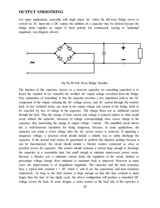
For many applications, especially with single phase AC where the full-wave bridge serves to
convert an AC input into a DC output, the addition of a capacitor may be desired because the
bridge alone supplies an output of fixed polarity but continuously varying or "pulsating"
magnitude (see diagram above).
Fig No.08 Full Wave Bridge Rectifier
The function of this capacitor, known as a reservoir capacitor (or smoothing capacitor) is to
lessen the variation in (or 'smooth') the rectified AC output voltage waveform from the bridge.
One explanation of 'smoothing' is that the capacitor provides a low impedance path to the AC
component of the output, reducing the AC voltage across, and AC current through, the resistive
load. In less technical terms, any drop in the output voltage and current of the bridge tends to
be canceled by loss of charge in the capacitor. This charge flows out as additional current
through the load. Thus the change of load current and voltage is reduced relative to what would
occur without the capacitor. Increases of voltage correspondingly store excess charge in the
capacitor, thus moderating the change in output voltage / current. The simplified circuit shown
has a well-deserved reputation for being dangerous, because, in some applications, the
capacitor can retain a lethal charge after the AC power source is removed. If supplying a
dangerous voltage, a practical circuit should include a reliable way to safely discharge the
capacitor. If the normal load cannot be guaranteed to perform this function, perhaps because it
can be disconnected, the circuit should include a bleeder resistor connected as close as
practical across the capacitor. This resistor should consume a current large enough to discharge
the capacitor in a reasonable time, but small enough to minimize unnecessary power waste.
Because a bleeder sets a minimum current drain, the regulation of the circuit, defined as
percentage voltage change from minimum to maximum load, is improved. However in many
cases the improvement is of insignificant magnitude. The capacitor and the load resistance
have a typical time constant τ = RC where C and R are the capacitance and load resistance
respectively. As long as the load resistor is large enough so that this time constant is much
longer than the time of one ripple cycle, the above configuration will produce a smoothed DC
voltage across the load. In some designs, a series resistor at the load side of the capacitor is
21
added. The smoothing can then be improved by adding additional stages of capacitor–resistor
pairs, often done only for sub-supplies to critical high-gain circuits that tend to be sensitive to
supply voltage noise.
The idealized waveforms shown above are seen for both voltage and current when the load on
the bridge is resistive. When the load includes a smoothing capacitor, both the voltage and the
current waveforms will be greatly changed. While the voltage is smoothed, as described above,
current will flow through the bridge only during the time when the input voltage is greater than
the capacitor voltage. For example, if the load draws an average current of n Amps, and the
diodes conduct for 10% of the time, the average diode current during conduction must be 10n
Amps. This non-sinusoidal current leads to harmonic distortion and a poor power factor in the
AC supply. In a practical circuit, when a capacitor is directly connected to the output of a
bridge, the bridge diodes must be sized to withstand the current surge that occurs when the
power is turned on at the peak of the AC voltage and the capacitor is fully discharged.
Sometimes a small series resistor is included before the capacitor to limit this current, though
in most applications the power supply transformer's resistance is already sufficient.
Output can also be smoothed using a choke and second capacitor. The choke tends to keep the
current (rather than the voltage) more constant. Due to the relatively high cost of an effective
choke compared to a resistor and capacitor this is not employed in modern equipment.
Some early console radios created the speaker's constant field with the current from the high
voltage ("B +") power supply, which was then routed to the consuming circuits, (permanent
magnets were then too weak for good performance) to create the speaker's constant magnetic
field. The speaker field coil thus performed 2 jobs in one: it acted as a choke, filtering the
power supply, and it produced the magnetic field to operate the speaker.
22
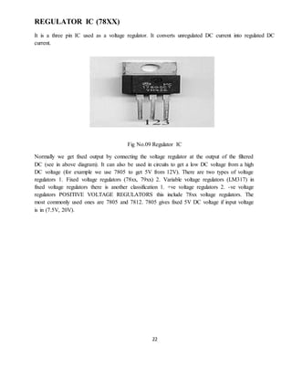
REGULATOR IC (78XX)
It is a three pin IC used as a voltage regulator. It converts unregulated DC current into regulated DC
current.
Fig No.09 Regulator IC
Normally we get fixed output by connecting the voltage regulator at the output of the filtered
DC (see in above diagram). It can also be used in circuits to get a low DC voltage from a high
DC voltage (for example we use 7805 to get 5V from 12V). There are two types of voltage
regulators 1. Fixed voltage regulators (78xx, 79xx) 2. Variable voltage regulators (LM317) in
fixed voltage regulators there is another classification 1. +ve voltage regulators 2. -ve voltage
regulators POSITIVE VOLTAGE REGULATORS this include 78xx voltage regulators. The
most commonly used ones are 7805 and 7812. 7805 gives fixed 5V DC voltage if input voltage
is in (7.5V, 20V).
23
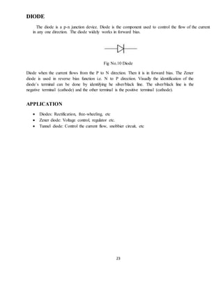
DIODE
The diode is a p-n junction device. Diode is the component used to control the flow of the current
in any one direction. The diode widely works in forward bias.
Fig No.10 Diode
Diode when the current flows from the P to N direction. Then it is in forward bias. The Zener
diode is used in reverse bias function i.e. N to P direction. Visually the identification of the
diode`s terminal can be done by identifying he silver/black line. The silver/black line is the
negative terminal (cathode) and the other terminal is the positive terminal (cathode).
APPLICATION
 Diodes: Rectification, free-wheeling, etc
 Zener diode: Voltage control, regulator etc.
 Tunnel diode: Control the current flow, snobbier circuit, etc
24
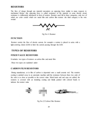
RESISTORS
The flow of charge through any material encounters an opposing force similar in many respects to
mechanical friction .this opposing force is called resistance of the material .in some electric circuit
resistance is deliberately introduced in form of resistor. Resistor used fall in three categories, only two of
which are color coded which are metal film and carbon film resistor .the third category is the wire
wound
Fig No.11 Resistor
FUNCTION
Resistor restrict the flow of electric current, for example a resistor is placed in series with a
light-emitting diode (LED) to limit the current passing through the LED.
TYPES OF RESISTORS
FIXED VALUE RESISTORS
It includes two types of resistors as carbon film and metal film
.These two types are explained under
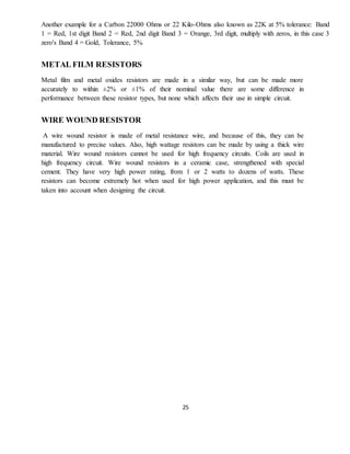
CARBON FILM RESISTORS
During manufacture, at in film of carbon is deposited onto a small ceramic rod. The resistive
coating is spiraled away in an automatic machine until the resistance between there two ends of
the rods is as close as possible to the correct value. Metal leads and end caps are added, the
resistors is covered with an insulating coating and finally painted with colored bands to
indicate the resistor value
Fig No.12 Carbon Film Resistor
25
Another example for a Carbon 22000 Ohms or 22 Kilo-Ohms also known as 22K at 5% tolerance: Band
1 = Red, 1st digit Band 2 = Red, 2nd digit Band 3 = Orange, 3rd digit, multiply with zeros, in this case 3
zero's Band 4 = Gold, Tolerance, 5%
METAL FILM RESISTORS
Metal film and metal oxides resistors are made in a similar way, but can be made more
accurately to within ±2% or ±1% of their nominal value there are some difference in
performance between these resistor types, but none which affects their use in simple circuit.
WIRE WOUND RESISTOR
A wire wound resistor is made of metal resistance wire, and because of this, they can be
manufactured to precise values. Also, high wattage resistors can be made by using a thick wire
material. Wire wound resistors cannot be used for high frequency circuits. Coils are used in
high frequency circuit. Wire wound resistors in a ceramic case, strengthened with special
cement. They have very high power rating, from 1 or 2 watts to dozens of watts. These
resistors can become extremely hot when used for high power application, and this must be
taken into account when designing the circuit.
26
CAPACITORS
In a way, a capacitor is a little like a battery. Although they work in completely different
ways, capacitors and batteries both store electrical energy. If you have read How Batteries
Work , then you know that a battery has two terminals. Inside the battery, chemical reactions
produce electrons on one terminal and absorb electrons at the other terminal.
BASIC
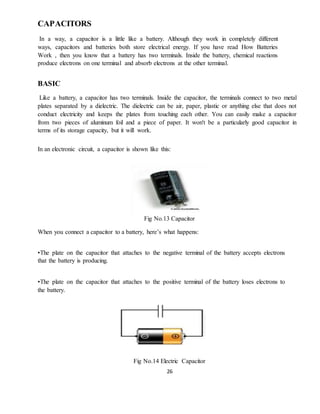
Like a battery, a capacitor has two terminals. Inside the capacitor, the terminals connect to two metal
plates separated by a dielectric. The dielectric can be air, paper, plastic or anything else that does not
conduct electricity and keeps the plates from touching each other. You can easily make a capacitor
from two pieces of aluminum foil and a piece of paper. It won't be a particularly good capacitor in
terms of its storage capacity, but it will work.
In an electronic circuit, a capacitor is shown like this:
Fig No.13 Capacitor
When you connect a capacitor to a battery, here’s what happens:
•The plate on the capacitor that attaches to the negative terminal of the battery accepts electrons
that the battery is producing.
•The plate on the capacitor that attaches to the positive terminal of the battery loses electrons to
the battery.
Fig No.14 Electric Capacitor
27
LED
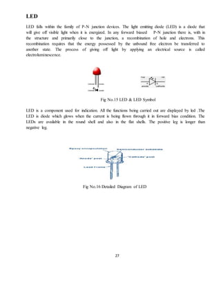
LED falls within the family of P-N junction devices. The light emitting diode (LED) is a diode that
will give off visible light when it is energized. In any forward biased P-N junction there is, with in
the structure and primarily close to the junction, a recombination of hole and electrons. This
recombination requires that the energy possessed by the unbound free electron be transferred to
another state. The process of giving off light by applying an electrical source is called
electroluminescence.
Fig No.15 LED & LED Symbol
LED is a component used for indication. All the functions being carried out are displayed by led .The
LED is diode which glows when the current is being flown through it in forward bias condition. The
LEDs are available in the round shell and also in the flat shells. The positive leg is longer than
negative leg.
Fig No.16 Detailed Diagram of LED
28
DC MOTOR
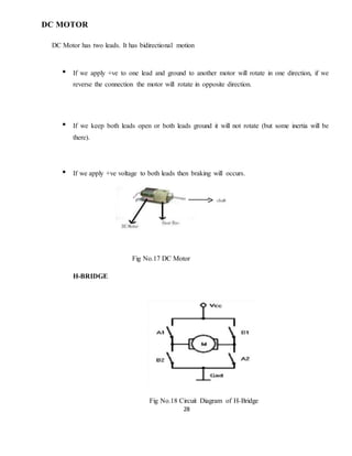
DC Motor has two leads. It has bidirectional motion
• If we apply +ve to one lead and ground to another motor will rotate in one direction, if we
reverse the connection the motor will rotate in opposite direction.
• If we keep both leads open or both leads ground it will not rotate (but some inertia will be
there).
• If we apply +ve voltage to both leads then braking will occurs.
Fig No.17 DC Motor
H-BRIDGE
Fig No.18 Circuit Diagram of H-Bridge
29
This circuit is known as H-Bridge because it looks like ” H” Working principle of H-Bridge.
• If switch (A1 and A2 )are on and switch (B1 and B2) are off then motor rotates in
clockwise direction
• If switch (B1 and B2 )are on and switch (A1 and A2) are off then motor rotates in Anti
clockwise direction
• we can use Transistor, mosfets as a switch ( Study the transistor as a a switch)
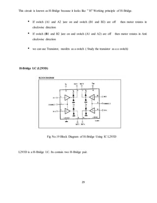
H-Bridge I.C (L293D)
Fig No.19 Block Diagram of H-Bridge Using IC L293D
L293D is a H-Bridge I.C. Its contain two H-Bridge pair.
30
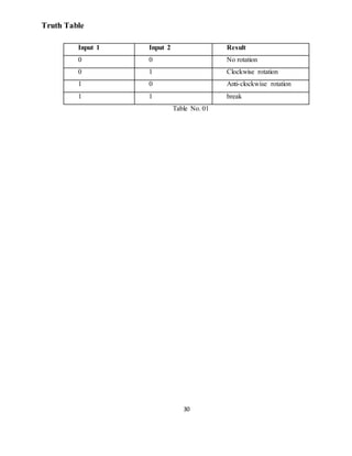
Truth Table
Input 1 Input 2 Result
0 0 No rotation
0 1 Clockwise rotation
1 0 Anti-clockwise rotation
1 1 break
Table No. 01
31
SCHEMATIC OF L293D WITH DC MOTOR
Fig No.20 Schematic Diagram of L293D with DC Motor
15 V DC+
L293D
2
7
10
15
1
9
3
6
11
14
16
8
IN1
IN2
IN3
IN4
EN1
EN2
OUT1
OUT2
OUT3
OUT4
VSS
VS
V DC+5
DUAL H-BRIDGE
5 V DC+
DC MOTOR
1
2
DC MOTOR
1
2
32
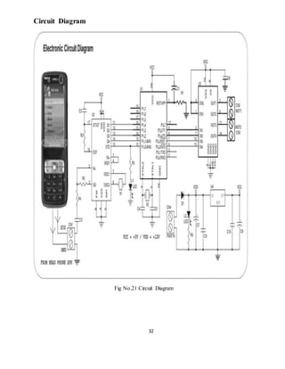
Circuit Diagram
Fig No.21 Circuit Diagram
33
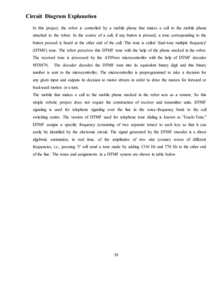
Circuit Diagram Explanation
In this project, the robot is controlled by a mobile phone that makes a call to the mobile phone
attached to the robot. In the course of a call, if any button is pressed, a tone corresponding to the
button pressed is heard at the other end of the call. This tone is called 'dual-tone multiple frequency'
(DTMF) tone. The robot perceives this DTMF tone with the help of the phone stacked in the robot.
The received tone is processed by the AT89xxx microcontroller with the help of DTMF decoder
MT8870. The decoder decodes the DTMF tone into its equivalent binary digit and this binary
number is sent to the microcontroller. The microcontroller is preprogrammed to take a decision for
any given input and outputs its decision to motor drivers in order to drive the motors for forward or
backward motion or a turn.
The mobile that makes a call to the mobile phone stacked in the robot acts as a remote. So this
simple robotic project does not require the construction of receiver and transmitter units. DTMF
signaling is used for telephone signaling over the line in the voice-frequency band to the call
switching centre. The version of DTMF used for telephone tone dialing is known as 'Touch-Tone.”
DTMF assigns a specific frequency (consisting of two separate tones) to each key so that it can
easily be identified by the electronic circuit. The signal generated by the DTMF encoder is a direct
algebraic summation, in real time, of the amplitudes of two sine (cosine) waves of different
frequencies, i.e., pressing '5' will send a tone made by adding 1336 Hz and 770 Hz to the other end
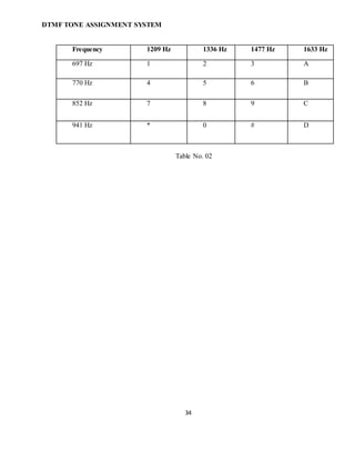
of the line. The tones and assignments in a DTMF system are shown in table below
34
DTMF TONE ASSIGNMENT SYSTEM
Frequency 1209 Hz 1336 Hz 1477 Hz 1633 Hz
697 Hz 1 2 3 A
770 Hz 4 5 6 B
852 Hz 7 8 9 C
941 Hz * 0 # D
Table No. 02
35
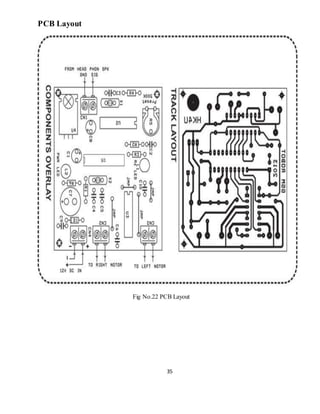
PCB Layout
Fig No.22 PCB Layout
36
Component List
R1 - 10K [BROWN, BLACK, ORANGE]
R2 - 270K [RED, VIIOLET, YELLOW]
R3 - 220E [RED, RED, BROWN]
R4 - 22K [RED, RED, ORANGE]
R6 - 1K [BROWN, BLACK, RED]
R5 - 500K PRESET
C1 - 10UF / 25V Electrolytic
C2, 6, 9, 10 - 100KPF DISC (0.1UF / 104) (4 NOS)
C3 - 100KPF POLY (0.1UF / 104)
C4, 5 - 33PF Ceramic Disc (2 NOS)
C7 - 1000UF / 16V Electrolytic
C8 - 47UF / 25V Electrolytic
X1 - 3.579545 MHZ Crystal
X2 - 11.0592 MHZ Crystal
D1 - 1N4007 Diode
L1 - 3 mm OR 5 mm RED LED
L2 - 3 mm OR 5 mm GREEN LED
U1 - AT89C2051 - MICROCONTROLLER (Pre Programmed MCU)
U2 - MT8870 - DTMF DECODER
U3 - L293 MOTOR DRIVER
U4 - LM7805 - +5V Voltage Regulator
CN1 ~ 4 - 2 PIN SCREW TERMINALS BLOCK (4 NOS)
1 nos - 20 PIN IC SOCKET FOR U1
1 nos - 18 PIN IC SOCKET FOR U2
1 nos - 16 PIN IC SOCKET FOR U3
1 nos - standard NOKIA Head phone Pin
37
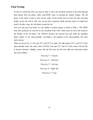
Final Testing
In order to control the robot, you need to make a call to the cell phone attached to the robot (through
head phone) from am phone, which send-DTMF tunes on pressing the numeric buttons. The cell
phone in the robot is kept in 'auto answer' mode. (If the mobile does not have the auto answering
facility, receive the call by 'OK' key on the robot connected mobile and then made it in hands-free
mode.) So after a ring, the cell phone accepts the call.
Now you ma)' press any button on your mobile to perform actions as listed in Table 2. The DTMF
tones thus produced are received by the cell phone in the robot. These tones are fed to the circuit by
the headset of the cell phone. The MT8870 decodes the received tone and sends the equivalent
binary number to the microcontroller. According to the program in the microcontroller, the robot
starts moving.
When you press key '2', Port pins P3.2 and P3.4 are high. The high output at P3.2 and P3.4 of the
microcontroller drives the motor driver (L293D). Port pins P3.3 and P3.4 drive motors Ml and M2
in forward direction. Similarly, motors Ml and M2 move for left turn, right turn, backward motion
and stop condition.
Press key '1' = forward
Press key '2' = backward
Press key '3' = Left turn
Press key '4' = Right turn
Press key '5' = Stop
38
Application
1) Scientific
Remote control vehicles have various scientific uses including hazardous environments,
working in the Deep Ocean, and space exploration. The majority of the probes to the other planets in
our solar system have been remote control vehicles, although some of the more recent ones were
partially autonomous. The sophistication of these devices has fueled greater debate on the need for
manned spaceflight and exploration.
2) Military and Law Enforcement
Military usage of remotely controlled military vehicles dates back to the first half of 20th
century. Soviet Red Army used remotely controlled Tele tanks during 1930s in the Winter War and
early stage of World War II.
3) Search and Rescue
UAVs will likely play an increased role in search and rescue in the United States. This was
demonstrated by the successful use of UAVs during the 2008 hurricanes that struck Louisiana and
Texas.
39
4) Recreation and Hobby
See Radio-controlled model. Small scale remote control vehicles have long been popular
among hobbyists. These remote controlled vehicles span a wide range in terms of price and
sophistication. There are many types of radio controlled vehicles. These include on-road cars, off-
road trucks, boats, airplanes, and even helicopters. The "robots" now popular in television shows
such as Robot Wars, are a recent extension of this hobby (these vehicles do not meet the classical
definition of a robot; they are remotely controlled by a human).
40
Future scope
1. IR Sensors
IR sensors can be used to automatically detect & avoid obstacles if the robot goes beyond line
of sight. This avoids damage to the vehicle if we are maneuvering it from a distant place.
2. Adding a Camera:
If the current project is interfaced with a camera (e.g. a Webcam) robot can be driven beyond
line-of-sight & range becomes practically unlimited as GSM networks have a very large range.
3. PasswordProtection
Project can be modified in order to password protect the robot so that it can be operated only if
correct password is entered. Either cell phone should be password protected or necessary
modification should be made in the assembly language code. This introduces conditioned access &
increases security to a great extent.
41
4. Alarm Phone Dialer
By replacing DTMF Decoder IC CM8870 by a 'DTMF Transceiver IC’ CM8880, DTMF tones can
be generated from the robot. So, a project called 'Alarm Phone Dialer' can be built which will
generate necessary alarms for something that is desired to be monitored (usually by triggering a
relay). For example, a high water alarm, low temperature alarm, opening of back window, garage
door, etc. When the system is activated it will call a number of programmed numbers to let the user
know the alarm has been activated. This would be great to get alerts of alarm conditions from home
when user is at work
42
Conclusion
By developing this robotic vehicle with its multi-tasking feature, I have overcome the drawbacks of
RF communication which have a limited range whereas this car can be controlled from anywhere
just using this DTMF technology. The main advantage of this robot is that it is password protected
so that any other person cannot communicate with the robot. It has various sensors and a LCD
screen in which the Humidity and Temperature of the place will be shown. S Considering all the
situations, the robot integrated with different sub modules can be used for redemption and security
purpose. DTMF Based Robot is the device which works on the specified network through a specific
phone.
43
References
By Books
Linear Integrated circuits : Ramakant Gaikwad
Electronic Devices and Circuits : Salivahan
Electronic Devices and Circuits : Millman and Halkias
Electronic Devices and Circuits : Boylestad
8051 and embedded system : Mazidi and Mazidi
By Websites
http:// www.datasheetcatalog.com
http:// www.atmel.com
http://www.electroschematics.com
http:// www.triindia.co.in
http://www.electronicsforu.com
http://8085projects.info
http://www.engineersgarage.com
http://www.ancastertouchatruck.com
http://www.instructables.com

More Related Content

What's hot

Bluetooth Controlled Robot
Bluetooth Controlled RobotBluetooth Controlled Robot
Bluetooth Controlled Robot
Pankaj Rai
 
Arduino dtmf controlled robot
Arduino dtmf controlled robotArduino dtmf controlled robot
Arduino dtmf controlled robot
UVSofts Technologies
 
Cell operated land rover robot
Cell operated land rover robotCell operated land rover robot
Cell operated land rover robot
Chetan Kataria
 
Cell Phone Controlled Robotic Vehicle
Cell Phone Controlled Robotic VehicleCell Phone Controlled Robotic Vehicle
Cell Phone Controlled Robotic Vehicle
Edgefxkits & Solutions
 
Cell Phone Operated Robot
Cell Phone Operated RobotCell Phone Operated Robot
Cell Phone Operated Robot
Aniket Bhor
 
DTMF Mobile Operated Robot using Atmega16
DTMF Mobile Operated Robot using Atmega16DTMF Mobile Operated Robot using Atmega16
DTMF Mobile Operated Robot using Atmega16
Prashant Saini
 
Ppt land rover
Ppt land roverPpt land rover
Ppt land roverAshu0711
 
project presentation on cell phone operated land rover
project presentation on cell phone operated land roverproject presentation on cell phone operated land rover
project presentation on cell phone operated land rover
sunanda kothari
 
Dtmf robot
Dtmf robotDtmf robot
Dtmf robot
ARCHANA S
 
Cell phone operated robot
Cell phone operated robotCell phone operated robot
Cell phone operated robot
Abhishek Rawat
 
Cell Phone Operated Land Rover
Cell Phone Operated Land RoverCell Phone Operated Land Rover
Cell Phone Operated Land RoverSayanton Vhaduri
 
DTMF CONTROLLED ROBOT
DTMF CONTROLLED ROBOTDTMF CONTROLLED ROBOT
DTMF CONTROLLED ROBOT
narendra019
 
Cellphone land rover using micro controller
Cellphone land rover using micro controllerCellphone land rover using micro controller
Cellphone land rover using micro controllerharideepu
 
Cell Phone Operated Robot for Search and Research of an Object
Cell Phone Operated Robot for Search and Research of an ObjectCell Phone Operated Robot for Search and Research of an Object
Cell Phone Operated Robot for Search and Research of an Object
Nikita Kaushal
 
Project on gsm based mobile controlling robot
Project on gsm based mobile controlling robotProject on gsm based mobile controlling robot
Project on gsm based mobile controlling robot
Anwarul Islam Mithu
 
Mobile operated spy robot
Mobile operated spy robotMobile operated spy robot
Mobile operated spy robot
Kevin Nesamani
 
Bluetooth Controlled Robot/Car
Bluetooth Controlled Robot/CarBluetooth Controlled Robot/Car
Bluetooth Controlled Robot/Car
Varun A M
 
Wireless robo Report
Wireless robo  ReportWireless robo  Report
Wireless robo Report
Sumit Saini
 
Presentation1
Presentation1Presentation1
Presentation1
ARCHANA S
 

What's hot (20)

Bluetooth Controlled Robot
Bluetooth Controlled RobotBluetooth Controlled Robot
Bluetooth Controlled Robot
 
Arduino dtmf controlled robot
Arduino dtmf controlled robotArduino dtmf controlled robot
Arduino dtmf controlled robot
 
Cell operated land rover robot
Cell operated land rover robotCell operated land rover robot
Cell operated land rover robot
 
Cell Phone Controlled Robotic Vehicle
Cell Phone Controlled Robotic VehicleCell Phone Controlled Robotic Vehicle
Cell Phone Controlled Robotic Vehicle
 
Cell Phone Operated Robot
Cell Phone Operated RobotCell Phone Operated Robot
Cell Phone Operated Robot
 
DTMF Mobile Operated Robot using Atmega16
DTMF Mobile Operated Robot using Atmega16DTMF Mobile Operated Robot using Atmega16
DTMF Mobile Operated Robot using Atmega16
 
Ppt land rover
Ppt land roverPpt land rover
Ppt land rover
 
project presentation on cell phone operated land rover
project presentation on cell phone operated land roverproject presentation on cell phone operated land rover
project presentation on cell phone operated land rover
 
Dtmf robot
Dtmf robotDtmf robot
Dtmf robot
 
Cell phone operated robot
Cell phone operated robotCell phone operated robot
Cell phone operated robot
 
Cell Phone Operated Land Rover
Cell Phone Operated Land RoverCell Phone Operated Land Rover
Cell Phone Operated Land Rover
 
DTMF CONTROLLED ROBOT
DTMF CONTROLLED ROBOTDTMF CONTROLLED ROBOT
DTMF CONTROLLED ROBOT
 
Cellphone land rover using micro controller
Cellphone land rover using micro controllerCellphone land rover using micro controller
Cellphone land rover using micro controller
 
Major
MajorMajor
Major
 
Cell Phone Operated Robot for Search and Research of an Object
Cell Phone Operated Robot for Search and Research of an ObjectCell Phone Operated Robot for Search and Research of an Object
Cell Phone Operated Robot for Search and Research of an Object
 
Project on gsm based mobile controlling robot
Project on gsm based mobile controlling robotProject on gsm based mobile controlling robot
Project on gsm based mobile controlling robot
 
Mobile operated spy robot
Mobile operated spy robotMobile operated spy robot
Mobile operated spy robot
 
Bluetooth Controlled Robot/Car
Bluetooth Controlled Robot/CarBluetooth Controlled Robot/Car
Bluetooth Controlled Robot/Car
 
Wireless robo Report
Wireless robo  ReportWireless robo  Report
Wireless robo Report
 
Presentation1
Presentation1Presentation1
Presentation1
 

Viewers also liked

Mobile controll robot
Mobile controll robotMobile controll robot
Mobile controll robot
UVSofts Technologies
 
Dtmf controlled bomb detecting robot
Dtmf controlled bomb detecting robotDtmf controlled bomb detecting robot
Dtmf controlled bomb detecting robot
Logic Mind Technologies
 
Android Operated Wireless Robot Using 8051 MCU
Android Operated Wireless Robot Using 8051 MCUAndroid Operated Wireless Robot Using 8051 MCU
Android Operated Wireless Robot Using 8051 MCUKamal Pradhan
 
GSM Based Wireless Robot Vehicle with POF features using DTMF
GSM Based Wireless Robot Vehicle with POF features using DTMFGSM Based Wireless Robot Vehicle with POF features using DTMF
GSM Based Wireless Robot Vehicle with POF features using DTMF
irjes
 
Mni projects sc
Mni projects scMni projects sc
Mni projects scindiaesys
 
GSM Based Versatile Robotic Vehicle Using PIC Microcontroller Report.
GSM Based Versatile Robotic Vehicle Using PIC Microcontroller Report.GSM Based Versatile Robotic Vehicle Using PIC Microcontroller Report.
GSM Based Versatile Robotic Vehicle Using PIC Microcontroller Report.
Abee Sharma
 
Arduino bluetooth controlled robot
Arduino bluetooth controlled robotArduino bluetooth controlled robot
Arduino bluetooth controlled robot
UVSofts Technologies
 
BLUETOOTH CONTROL ROBOT WITH ANDROID APPLICATION
BLUETOOTH CONTROL ROBOT WITH ANDROID APPLICATIONBLUETOOTH CONTROL ROBOT WITH ANDROID APPLICATION
BLUETOOTH CONTROL ROBOT WITH ANDROID APPLICATION
Varun Divekar
 
android controlled robot
android controlled robotandroid controlled robot
android controlled robot
sunny080593
 
Android controlled robot
Android controlled robotAndroid controlled robot
Android controlled robotBen Johnke
 
Wireless robot ppt
Wireless robot pptWireless robot ppt
Wireless robot pptVarun B P
 
Mobile Operated Landrover Using Dtmf Decoder
Mobile Operated Landrover Using Dtmf DecoderMobile Operated Landrover Using Dtmf Decoder
Mobile Operated Landrover Using Dtmf Decoder
IJMER
 
Wireless Pick and Place Surveillance Robot
Wireless Pick and Place Surveillance RobotWireless Pick and Place Surveillance Robot
Wireless Pick and Place Surveillance Robot
Zeenat Saba Khan
 
Wireless Gesture Controlled Robot (FYP Report)
Wireless Gesture Controlled Robot (FYP Report)Wireless Gesture Controlled Robot (FYP Report)
Wireless Gesture Controlled Robot (FYP Report)Muhammad Ahkam Khan
 
WIRELESS ROBOT PPT
WIRELESS ROBOT PPTWIRELESS ROBOT PPT
WIRELESS ROBOT PPT
AIRTEL
 

Viewers also liked (15)

Mobile controll robot
Mobile controll robotMobile controll robot
Mobile controll robot
 
Dtmf controlled bomb detecting robot
Dtmf controlled bomb detecting robotDtmf controlled bomb detecting robot
Dtmf controlled bomb detecting robot
 
Android Operated Wireless Robot Using 8051 MCU
Android Operated Wireless Robot Using 8051 MCUAndroid Operated Wireless Robot Using 8051 MCU
Android Operated Wireless Robot Using 8051 MCU
 
GSM Based Wireless Robot Vehicle with POF features using DTMF
GSM Based Wireless Robot Vehicle with POF features using DTMFGSM Based Wireless Robot Vehicle with POF features using DTMF
GSM Based Wireless Robot Vehicle with POF features using DTMF
 
Mni projects sc
Mni projects scMni projects sc
Mni projects sc
 
GSM Based Versatile Robotic Vehicle Using PIC Microcontroller Report.
GSM Based Versatile Robotic Vehicle Using PIC Microcontroller Report.GSM Based Versatile Robotic Vehicle Using PIC Microcontroller Report.
GSM Based Versatile Robotic Vehicle Using PIC Microcontroller Report.
 
Arduino bluetooth controlled robot
Arduino bluetooth controlled robotArduino bluetooth controlled robot
Arduino bluetooth controlled robot
 
BLUETOOTH CONTROL ROBOT WITH ANDROID APPLICATION
BLUETOOTH CONTROL ROBOT WITH ANDROID APPLICATIONBLUETOOTH CONTROL ROBOT WITH ANDROID APPLICATION
BLUETOOTH CONTROL ROBOT WITH ANDROID APPLICATION
 
android controlled robot
android controlled robotandroid controlled robot
android controlled robot
 
Android controlled robot
Android controlled robotAndroid controlled robot
Android controlled robot
 
Wireless robot ppt
Wireless robot pptWireless robot ppt
Wireless robot ppt
 
Mobile Operated Landrover Using Dtmf Decoder
Mobile Operated Landrover Using Dtmf DecoderMobile Operated Landrover Using Dtmf Decoder
Mobile Operated Landrover Using Dtmf Decoder
 
Wireless Pick and Place Surveillance Robot
Wireless Pick and Place Surveillance RobotWireless Pick and Place Surveillance Robot
Wireless Pick and Place Surveillance Robot
 
Wireless Gesture Controlled Robot (FYP Report)
Wireless Gesture Controlled Robot (FYP Report)Wireless Gesture Controlled Robot (FYP Report)
Wireless Gesture Controlled Robot (FYP Report)
 
WIRELESS ROBOT PPT
WIRELESS ROBOT PPTWIRELESS ROBOT PPT
WIRELESS ROBOT PPT
 

Similar to Pankaj project report

Cell Phone Operated Land Rover
Cell Phone Operated Land RoverCell Phone Operated Land Rover
Cell Phone Operated Land Rover
Sanjay Talukdar
 
Iaetsd design and implementation of mobile operated
Iaetsd design and implementation of mobile operatedIaetsd design and implementation of mobile operated
Iaetsd design and implementation of mobile operated
Iaetsd Iaetsd
 
Dual tone multiple frequency
Dual tone multiple frequencyDual tone multiple frequency
Dual tone multiple frequency
Srilekha K
 
Mobile Controlled Car
Mobile Controlled CarMobile Controlled Car
Mobile Controlled CarMalik Zaid
 
IRJET- DTMF based Control Robot using Arduino
IRJET- DTMF based Control Robot using ArduinoIRJET- DTMF based Control Robot using Arduino
IRJET- DTMF based Control Robot using Arduino
IRJET Journal
 
DTM Decoder
DTM DecoderDTM Decoder
DTM Decoder
Mohsin Ali
 
Home automation using dtmf
Home automation using dtmfHome automation using dtmf
Home automation using dtmf
Pratik Gupta
 
Mobile operated landrover using dtmf decoder
Mobile operated landrover using dtmf decoderMobile operated landrover using dtmf decoder
Mobile operated landrover using dtmf decoder
Logic Mind Technologies
 
final ppt2.pptx
final ppt2.pptxfinal ppt2.pptx
final ppt2.pptx
AnshuAgarwal48
 
Arm Robot Surveillance Using Dual Tone Multiple Frequency Technology
Arm Robot Surveillance Using Dual Tone Multiple Frequency TechnologyArm Robot Surveillance Using Dual Tone Multiple Frequency Technology
Arm Robot Surveillance Using Dual Tone Multiple Frequency Technology
IJERA Editor
 
Mobile controlled robot
Mobile controlled robotMobile controlled robot
Mobile controlled robot
UVSofts Technologies
 
Microcontroller remote controlling project
Microcontroller  remote controlling projectMicrocontroller  remote controlling project
Microcontroller remote controlling project
Bipro Roy
 
Mine detecting robot
Mine detecting robot Mine detecting robot
Mine detecting robot Rahul Singh
 
Dtmf robot
Dtmf robot Dtmf robot
Dtmf robot
Jeevan M
 
DTMF based home automation with ADRUINO
DTMF based home automation with ADRUINODTMF based home automation with ADRUINO
DTMF based home automation with ADRUINO
Fucck
 
Mobile Phone Operated Dual-tone-multiple-frequency controlled Microcontroller...
Mobile Phone Operated Dual-tone-multiple-frequency controlled Microcontroller...Mobile Phone Operated Dual-tone-multiple-frequency controlled Microcontroller...
Mobile Phone Operated Dual-tone-multiple-frequency controlled Microcontroller...
IOSRJEEE
 
BE Project Fortnight Reports on IVRS
BE Project Fortnight Reports on IVRSBE Project Fortnight Reports on IVRS
BE Project Fortnight Reports on IVRSAbhishek Nadkarni
 
IRJET- DTMF Controlled Robotic Car
IRJET-  	  DTMF Controlled Robotic CarIRJET-  	  DTMF Controlled Robotic Car
IRJET- DTMF Controlled Robotic Car
IRJET Journal
 
Dtmf technology
Dtmf technologyDtmf technology
Dtmf technology
tchikou10
 

Similar to Pankaj project report (20)

Cell Phone Operated Land Rover
Cell Phone Operated Land RoverCell Phone Operated Land Rover
Cell Phone Operated Land Rover
 
Iaetsd design and implementation of mobile operated
Iaetsd design and implementation of mobile operatedIaetsd design and implementation of mobile operated
Iaetsd design and implementation of mobile operated
 
Dual tone multiple frequency
Dual tone multiple frequencyDual tone multiple frequency
Dual tone multiple frequency
 
Mobile Controlled Car
Mobile Controlled CarMobile Controlled Car
Mobile Controlled Car
 
IRJET- DTMF based Control Robot using Arduino
IRJET- DTMF based Control Robot using ArduinoIRJET- DTMF based Control Robot using Arduino
IRJET- DTMF based Control Robot using Arduino
 
DTM Decoder
DTM DecoderDTM Decoder
DTM Decoder
 
Home automation using dtmf
Home automation using dtmfHome automation using dtmf
Home automation using dtmf
 
Mobile operated landrover using dtmf decoder
Mobile operated landrover using dtmf decoderMobile operated landrover using dtmf decoder
Mobile operated landrover using dtmf decoder
 
final ppt2.pptx
final ppt2.pptxfinal ppt2.pptx
final ppt2.pptx
 
Arm Robot Surveillance Using Dual Tone Multiple Frequency Technology
Arm Robot Surveillance Using Dual Tone Multiple Frequency TechnologyArm Robot Surveillance Using Dual Tone Multiple Frequency Technology
Arm Robot Surveillance Using Dual Tone Multiple Frequency Technology
 
Mobile controlled robot
Mobile controlled robotMobile controlled robot
Mobile controlled robot
 
Microcontroller remote controlling project
Microcontroller  remote controlling projectMicrocontroller  remote controlling project
Microcontroller remote controlling project
 
Mine detecting robot
Mine detecting robot Mine detecting robot
Mine detecting robot
 
Dtmf robot
Dtmf robot Dtmf robot
Dtmf robot
 
DTMF based home automation with ADRUINO
DTMF based home automation with ADRUINODTMF based home automation with ADRUINO
DTMF based home automation with ADRUINO
 
Mobile Phone Operated Dual-tone-multiple-frequency controlled Microcontroller...
Mobile Phone Operated Dual-tone-multiple-frequency controlled Microcontroller...Mobile Phone Operated Dual-tone-multiple-frequency controlled Microcontroller...
Mobile Phone Operated Dual-tone-multiple-frequency controlled Microcontroller...
 
BE Project Fortnight Reports on IVRS
BE Project Fortnight Reports on IVRSBE Project Fortnight Reports on IVRS
BE Project Fortnight Reports on IVRS
 
IRJET- DTMF Controlled Robotic Car
IRJET-  	  DTMF Controlled Robotic CarIRJET-  	  DTMF Controlled Robotic Car
IRJET- DTMF Controlled Robotic Car
 
SURVEILLANCE ROBOT
SURVEILLANCE ROBOTSURVEILLANCE ROBOT
SURVEILLANCE ROBOT
 
Dtmf technology
Dtmf technologyDtmf technology
Dtmf technology
 

Recently uploaded

H.Seo, ICLR 2024, MLILAB, KAIST AI.pdf
H.Seo,  ICLR 2024, MLILAB,  KAIST AI.pdfH.Seo,  ICLR 2024, MLILAB,  KAIST AI.pdf
H.Seo, ICLR 2024, MLILAB, KAIST AI.pdf
MLILAB
 
一比一原版(SFU毕业证)西蒙菲莎大学毕业证成绩单如何办理
一比一原版(SFU毕业证)西蒙菲莎大学毕业证成绩单如何办理一比一原版(SFU毕业证)西蒙菲莎大学毕业证成绩单如何办理
一比一原版(SFU毕业证)西蒙菲莎大学毕业证成绩单如何办理
bakpo1
 
Governing Equations for Fundamental Aerodynamics_Anderson2010.pdf
Governing Equations for Fundamental Aerodynamics_Anderson2010.pdfGoverning Equations for Fundamental Aerodynamics_Anderson2010.pdf
Governing Equations for Fundamental Aerodynamics_Anderson2010.pdf
WENKENLI1
 
Planning Of Procurement o different goods and services
Planning Of Procurement o different goods and servicesPlanning Of Procurement o different goods and services
Planning Of Procurement o different goods and services
JoytuBarua2
 
Design and Analysis of Algorithms-DP,Backtracking,Graphs,B&B
Design and Analysis of Algorithms-DP,Backtracking,Graphs,B&BDesign and Analysis of Algorithms-DP,Backtracking,Graphs,B&B
Design and Analysis of Algorithms-DP,Backtracking,Graphs,B&B
Sreedhar Chowdam
 
AKS UNIVERSITY Satna Final Year Project By OM Hardaha.pdf
AKS UNIVERSITY Satna Final Year Project By OM Hardaha.pdfAKS UNIVERSITY Satna Final Year Project By OM Hardaha.pdf
AKS UNIVERSITY Satna Final Year Project By OM Hardaha.pdf
SamSarthak3
 
CFD Simulation of By-pass Flow in a HRSG module by R&R Consult.pptx
CFD Simulation of By-pass Flow in a HRSG module by R&R Consult.pptxCFD Simulation of By-pass Flow in a HRSG module by R&R Consult.pptx
CFD Simulation of By-pass Flow in a HRSG module by R&R Consult.pptx
R&R Consult
 
weather web application report.pdf
weather web application report.pdfweather web application report.pdf
weather web application report.pdf
Pratik Pawar
 
space technology lecture notes on satellite
space technology lecture notes on satellitespace technology lecture notes on satellite
space technology lecture notes on satellite
ongomchris
 
MCQ Soil mechanics questions (Soil shear strength).pdf
MCQ Soil mechanics questions (Soil shear strength).pdfMCQ Soil mechanics questions (Soil shear strength).pdf
MCQ Soil mechanics questions (Soil shear strength).pdf
Osamah Alsalih
 
Water Industry Process Automation and Control Monthly - May 2024.pdf
Water Industry Process Automation and Control Monthly - May 2024.pdfWater Industry Process Automation and Control Monthly - May 2024.pdf
Water Industry Process Automation and Control Monthly - May 2024.pdf
Water Industry Process Automation & Control
 
Fundamentals of Electric Drives and its applications.pptx
Fundamentals of Electric Drives and its applications.pptxFundamentals of Electric Drives and its applications.pptx
Fundamentals of Electric Drives and its applications.pptx
manasideore6
 
NO1 Uk best vashikaran specialist in delhi vashikaran baba near me online vas...
NO1 Uk best vashikaran specialist in delhi vashikaran baba near me online vas...NO1 Uk best vashikaran specialist in delhi vashikaran baba near me online vas...
NO1 Uk best vashikaran specialist in delhi vashikaran baba near me online vas...
Amil Baba Dawood bangali
 
Immunizing Image Classifiers Against Localized Adversary Attacks
Immunizing Image Classifiers Against Localized Adversary AttacksImmunizing Image Classifiers Against Localized Adversary Attacks
Immunizing Image Classifiers Against Localized Adversary Attacks
gerogepatton
 
CME397 Surface Engineering- Professional Elective
CME397 Surface Engineering- Professional ElectiveCME397 Surface Engineering- Professional Elective
CME397 Surface Engineering- Professional Elective
karthi keyan
 
English lab ppt no titlespecENG PPTt.pdf
English lab ppt no titlespecENG PPTt.pdfEnglish lab ppt no titlespecENG PPTt.pdf
English lab ppt no titlespecENG PPTt.pdf
BrazilAccount1
 
Nuclear Power Economics and Structuring 2024
Nuclear Power Economics and Structuring 2024Nuclear Power Economics and Structuring 2024
Nuclear Power Economics and Structuring 2024
Massimo Talia
 
HYDROPOWER - Hydroelectric power generation
HYDROPOWER - Hydroelectric power generationHYDROPOWER - Hydroelectric power generation
HYDROPOWER - Hydroelectric power generation
Robbie Edward Sayers
 
Sachpazis:Terzaghi Bearing Capacity Estimation in simple terms with Calculati...
Sachpazis:Terzaghi Bearing Capacity Estimation in simple terms with Calculati...Sachpazis:Terzaghi Bearing Capacity Estimation in simple terms with Calculati...
Sachpazis:Terzaghi Bearing Capacity Estimation in simple terms with Calculati...
Dr.Costas Sachpazis
 
一比一原版(IIT毕业证)伊利诺伊理工大学毕业证成绩单专业办理
一比一原版(IIT毕业证)伊利诺伊理工大学毕业证成绩单专业办理一比一原版(IIT毕业证)伊利诺伊理工大学毕业证成绩单专业办理
一比一原版(IIT毕业证)伊利诺伊理工大学毕业证成绩单专业办理
zwunae
 

Recently uploaded (20)

H.Seo, ICLR 2024, MLILAB, KAIST AI.pdf
H.Seo,  ICLR 2024, MLILAB,  KAIST AI.pdfH.Seo,  ICLR 2024, MLILAB,  KAIST AI.pdf
H.Seo, ICLR 2024, MLILAB, KAIST AI.pdf
 
一比一原版(SFU毕业证)西蒙菲莎大学毕业证成绩单如何办理
一比一原版(SFU毕业证)西蒙菲莎大学毕业证成绩单如何办理一比一原版(SFU毕业证)西蒙菲莎大学毕业证成绩单如何办理
一比一原版(SFU毕业证)西蒙菲莎大学毕业证成绩单如何办理
 
Governing Equations for Fundamental Aerodynamics_Anderson2010.pdf
Governing Equations for Fundamental Aerodynamics_Anderson2010.pdfGoverning Equations for Fundamental Aerodynamics_Anderson2010.pdf
Governing Equations for Fundamental Aerodynamics_Anderson2010.pdf
 
Planning Of Procurement o different goods and services
Planning Of Procurement o different goods and servicesPlanning Of Procurement o different goods and services
Planning Of Procurement o different goods and services
 
Design and Analysis of Algorithms-DP,Backtracking,Graphs,B&B
Design and Analysis of Algorithms-DP,Backtracking,Graphs,B&BDesign and Analysis of Algorithms-DP,Backtracking,Graphs,B&B
Design and Analysis of Algorithms-DP,Backtracking,Graphs,B&B
 
AKS UNIVERSITY Satna Final Year Project By OM Hardaha.pdf
AKS UNIVERSITY Satna Final Year Project By OM Hardaha.pdfAKS UNIVERSITY Satna Final Year Project By OM Hardaha.pdf
AKS UNIVERSITY Satna Final Year Project By OM Hardaha.pdf
 
CFD Simulation of By-pass Flow in a HRSG module by R&R Consult.pptx
CFD Simulation of By-pass Flow in a HRSG module by R&R Consult.pptxCFD Simulation of By-pass Flow in a HRSG module by R&R Consult.pptx
CFD Simulation of By-pass Flow in a HRSG module by R&R Consult.pptx
 
weather web application report.pdf
weather web application report.pdfweather web application report.pdf
weather web application report.pdf
 
space technology lecture notes on satellite
space technology lecture notes on satellitespace technology lecture notes on satellite
space technology lecture notes on satellite
 
MCQ Soil mechanics questions (Soil shear strength).pdf
MCQ Soil mechanics questions (Soil shear strength).pdfMCQ Soil mechanics questions (Soil shear strength).pdf
MCQ Soil mechanics questions (Soil shear strength).pdf
 
Water Industry Process Automation and Control Monthly - May 2024.pdf
Water Industry Process Automation and Control Monthly - May 2024.pdfWater Industry Process Automation and Control Monthly - May 2024.pdf
Water Industry Process Automation and Control Monthly - May 2024.pdf
 
Fundamentals of Electric Drives and its applications.pptx
Fundamentals of Electric Drives and its applications.pptxFundamentals of Electric Drives and its applications.pptx
Fundamentals of Electric Drives and its applications.pptx
 
NO1 Uk best vashikaran specialist in delhi vashikaran baba near me online vas...
NO1 Uk best vashikaran specialist in delhi vashikaran baba near me online vas...NO1 Uk best vashikaran specialist in delhi vashikaran baba near me online vas...
NO1 Uk best vashikaran specialist in delhi vashikaran baba near me online vas...
 
Immunizing Image Classifiers Against Localized Adversary Attacks
Immunizing Image Classifiers Against Localized Adversary AttacksImmunizing Image Classifiers Against Localized Adversary Attacks
Immunizing Image Classifiers Against Localized Adversary Attacks
 
CME397 Surface Engineering- Professional Elective
CME397 Surface Engineering- Professional ElectiveCME397 Surface Engineering- Professional Elective
CME397 Surface Engineering- Professional Elective
 
English lab ppt no titlespecENG PPTt.pdf
English lab ppt no titlespecENG PPTt.pdfEnglish lab ppt no titlespecENG PPTt.pdf
English lab ppt no titlespecENG PPTt.pdf
 
Nuclear Power Economics and Structuring 2024
Nuclear Power Economics and Structuring 2024Nuclear Power Economics and Structuring 2024
Nuclear Power Economics and Structuring 2024
 
HYDROPOWER - Hydroelectric power generation
HYDROPOWER - Hydroelectric power generationHYDROPOWER - Hydroelectric power generation
HYDROPOWER - Hydroelectric power generation
 
Sachpazis:Terzaghi Bearing Capacity Estimation in simple terms with Calculati...
Sachpazis:Terzaghi Bearing Capacity Estimation in simple terms with Calculati...Sachpazis:Terzaghi Bearing Capacity Estimation in simple terms with Calculati...
Sachpazis:Terzaghi Bearing Capacity Estimation in simple terms with Calculati...
 
一比一原版(IIT毕业证)伊利诺伊理工大学毕业证成绩单专业办理
一比一原版(IIT毕业证)伊利诺伊理工大学毕业证成绩单专业办理一比一原版(IIT毕业证)伊利诺伊理工大学毕业证成绩单专业办理
一比一原版(IIT毕业证)伊利诺伊理工大学毕业证成绩单专业办理
 

Pankaj project report

  • 1. 1 Project Report ON DTMF Based Mobile Controlled Robot Submitted In Partial Fulfillment of the Requirements for the Diploma of Electronics and Telecommunication Engineering By Mr. Pankaj Rai Under the guidance of Ms. Meenal Vatsaraj DEPARTMENT OF ELECTRONICS AND TELECOMMUNICATION ENGINEERING (DIPLOMA) ARMIET Alamuri Ratnamala Institute of Engineering and Technology (Run by Koti Vidya Charitable Trust) A.S. Rao Nagar, Sapgaon, Tal Shahapur, Dist Thane-421601
  • 2. 2 Alamuri Ratnamala Institute of Engineering and Technology (Run by Koti Vidya Charitable Trust) A.S. Rao Nagar, Sapgaon, Tal Shahapur, Dist Thane-421601 Project Report Submitted By Name: Mr. Pankaj Rai. Title of project: DTMF BASED MOBILECONTROLLED ROBOT Guide Name: Ms. Meenal Vatsaraj Ms. Meenal Vatsaraj Mr. C. Nagababu Mr. C. Nagababu (Project Guide) (H.O.D.) (Principal)
  • 3. 3 CERTIFICATE This is to certify that Mr. Pankaj Shivchander Rai of PIN ARMIET/DIP/ET-14 RP 217 has delivered a project report for the Project Topic “DTMF Based Mobile Controlled Robot” and submitted report in the “Alamuri Ratnamala Institute of Engineering and Technology”, Sapgaon, Tal Shahapur, Dist, Thane, in the partial fulfillment of the diploma of “Electronics and telecommunication Engineering” from MSBTE for the year 2015-16 Guide H.O.D. Principal Meenal Vatsaraj Nagababu Chekuri Nagababu Chekuri
  • 4. 4 Acknowledgement I would like to acknowledge and extend our heartfelt gratitude to all those people who have been associated with this project and have helped us with it thus making it a worthwhile experience. Firstly I extend our thanks to various people which include my project Guide Ms. Meenal Vatsaraj, my H.O.D. Nagababu Chekuri, who have shared their opinions and experiences through which I received the required information for my report. I am also thankful to all the staff members of EXTC Dept. for their highly cooperative and encouraging attitudes, which have always boosted me. I also take this opportunity with great pleasure to thank our Honorable Founder Trustee A.V. Gupta, Honorable Alternate Chairman Dr. L.S. Bothra and Principal Prof. Nagababu Chekuri whose timely support and encouragement has helped us succeeds in our venture. Pankaj Rai
  • 5. 5 INDEX Sr. No. Topic Name Page No. 1 Abstract 08 2 Introduction 09 3 Block Diagram 11 4 Explanation Of Block Diagram 12 5 Hardware Description 14 a) Power Supply 14 b) Transformer 15 i. Basic Parts Of Transformer 16 ii. Components Of Transformer 17 c) Bridge Rectifier 18 i. Basic Operation 18 ii. Output Smoothing 20 d) Regulator IC 22 e) Diode 23 f) Resistor 24 g) Capacitor 26 h) LED 27 i) DC Motor 28 6 Circuit Diagram 32 7 Explanation of Circuit Diagram 33 8 PCB Layout 35 9 Component List 36 10 Final Testing 37 11 Application 38 12 Future Scope 40 13 Conclusion 42 14 Reference 43
  • 6. 6 Table Description Sr. No. Table No. Table Name Page No. 1 01 Truth Table 30 2 02 DTMF Tone Assignment System 34
  • 7. 7 DiagramDescription Sr. No. Diagram No. Diagram Name Page No. 1 01 Basic Block Diagram 01 11 2 02 Basic Block Diagram 02 11 3 03 Circuit Diagram of Power Supply 14 4 04 Transformer 15 5 05 Basic Circuit Diagram of Transform 16 6 06 Basic Circuit Diagram of Bridge Rectifier 18 7 07 Basic Circuit Diagram of Bridge Rectifier 19 8 08 Full Wave Bridge Rectifier 20 9 09 Regulator IC 22 10 10 Diode 23 11 11 Resistor 24 12 12 Carbon Film Resistor 24 13 13 Capacitor 26 14 14 Electronic Capacitor 26 15 15 LED & LED Symbol 27 16 16 Detailed Diagram of LED 27 17 17 DC Motor 28 18 18 Circuit Diagram of H-Bridge 28 19 19 Block Diagram of H-Bridge Using IC L293D 29 20 20 Schematic Diagram of L293D with DC Motor 31 21 21 Circuit Diagram 32 22 22 PCB Layout 35
  • 8. 8 Abstract DTMF Mobile ROBO is a machine that can be controlled with a mobile. The robot is controlled by a mobile phone that makes a call to the mobile phone attached to the robot. In this course of a call, if any button is pressed a tone corresponding to the button pressed is heard at the other end of end of the call. This type of tone is called s “Dual Tone Multiple Frequency” (DTMF) tone. The received tone is processed by the atmega16 microcontroller with the help of DTMF decoder MT8870 the decoder decodes the DTMF tone in to its equivalent binary digit and this binary number is send to the microcontroller, the microcontroller is preprogrammed to take a decision for any give input and outputs Its decision to motor drivers in order to drive the motors for forward or backward motion or a turn. The mobile that makes a call to the mobile phone stacked in the robot acts as a remote. So this simple robotic project does not require the construction of receiver and transmitter units. DTMF signaling is used for telephone signaling over the line in the voice frequency band to the call switching center. The version of DTMF used for telephone dialing is known as touch tone. DTMF assigns a specific frequency (consisting of two separate tones) to each key s that it can easily be identified by the electronic circuit.
  • 9. 9 Introduction DTMF Mobile ROBO is a machine that can be controlled with a mobile. In this project, the robot is controlled by a mobile phone that makes a call to the mobile phone attached to the robot. In the course of a call, if any button is pressed, a tone corresponding to the button pressed is heard at the other end of the call. This tone is called "Dual Tone Multiple-Frequency" (DTMF) tone. The robot perceives this DTMF tone with the help of the phone stacked on the robot. The received tone is processed by the microcontroller with the help of DTMF decoder. The microcontroller then transmits the signal to the motor driver ICs to operate the motors & our robot starts moving Conventionally, Wireless-controlled robots use RF circuits, which have the drawbacks of limited working range, limited frequency range and the limited control. Use of a mobile phone for robotic control can overcome these limitations. It provides the advantage of robust control, working range as large as the coverage area of the service provider, no interference with other controllers and up to twelve controls. Although the appearance and the capabilities of robots vary vastly, all robots share the feature of a mechanical, movable structure under some form of control. The Control of robot involves three distinct phases: perception, processing and action. Generally, the preceptors are sensors mounted on the robot, processing is done by the on-board microcontroller or processor, and the task is performed using motors or with some other actuators. In this project the robot, is controlled by a mobile phone that makes call to the mobile phone attached to the robot in the course of the call, if any button is pressed control corresponding to the button pressed is heard at the other end of the call. This tone is called dual tone multi frequency tome (DTMF) robot receives this DTMF tone with the help of phone stacked in the robot The received tone is processed by the atmega16 microcontroller with the help of DTMF decoder MT8870 the decoder decodes the DTMF tone in to its equivalent binary digit and this binary number is send to the microcontroller, the microcontroller is preprogrammed to take a decision for any give input and outputs its decision to motor drivers in order to drive the motors for forward or backward motion or a turn. The mobile that makes a call to the mobile phone stacked in the robot acts as a remote. So this simple robotic project does not require the construction of receiver and transmitter units. DTMF signaling is used for telephone signaling over the line in the voice frequency band to the call switching center. The version of DTMF used for telephone dialing is known as touch tone. DTMF assigns a specific frequency (consisting of two separate tones) to each key s that it can easily be identified by the electronic circuit. The signal generated by the DTMF encoder is the direct algebraic submission, in real time of the amplitudes of two sine (cosine) waves of different frequencies, i.e., pressing 5 will send a tone made by adding 1336 Hz
  • 10. 10 and 770 Hz to the other end of the mobile. The important components of this robot are DTMF decoder, Microcontroller and motor driver. An MT8870 series DTMF decoder is used here. All types of the mt8870 series use digital counting techniques to detect and decode all the sixteen DTMF tone pairs in to a four bit code output. The built -in dial tone rejection circuit eliminated the need for pre- filtering. When the input signal given at pin2 (IN-) single ended input configuration is recognized to be effective, the correct four bit decode signal of the DTMF tone is transferred to Q1 (pin11) through Q4(pin14) outputs
  • 11. 11 Block Diagram Fig No.01 Basic Block Diagram 01 Fig No.02 Basic Block Diagram 02 L293D POWER SUPPLY TELEPHONE DTMF DECODER MOTOR 8051 MICROCONTR OLLER MOTOR
  • 12. 12 Explanation of Block Diagram Cellphone Cellphone is the basic input device of this project. Cellphone is used to give the input to the DTMF decoder. It uses RF signal to communicate with DTMF decoder. DTMF Decoder Today, most telephone equipment use a DTMF receiver IC. One common DTMF receiver IC is the Motorola MT8870 that is widely used in electronic communications circuits. The MT8870 is an 18-pin IC. It is used in telephones and a variety of other applications. When a proper output is not obtained in projects using this IC, engineers or technicians need to test this IC separately. A quick testing of this IC could save a lot of time in re-search labs and manufacturing industries of communication instruments. Here’s a small and handy tester circuit for the DTMF IC. It can be assembled on a multipurpose PCB with an 18-pin IC base. One can also test the IC on a simple breadboard. For optimum working of telephone equipment, the DTMF receiver must be designed to recognize a valid tone pair greater than 40 ms in duration and to accept successive digit tone- pairs that are greater than 40 ms apart. However, for other applications like remote controls and radio communications, the tone duration may differ due to noise considerations. Therefore, by adding an extra resistor and steering diode the tone duration can be set to different values. The circuit is configured in balanced-line mode. To reject common-mode noise signals, a balanced differential amplifier input is used. The circuit also provides an excellent bridging interface across a properly terminated telephone line. Transient protection may be achieved by splitting the input resistors and inserting ZENER diodes (ZD1 and ZD2) to achieve voltage clamping. This allows the transient energy to be dissipated in the resistors and diodes, and limits the maximum voltage that may appear at the inputs. Whenever you press any key on your local telephone keypad, the delayed steering (Std) output of the IC goes high on receiving the tone- pair, causing LED5 (connected to pin 15 of IC via resistor R15) to glow. It will be high for a duration depending on the values of capacitor and resistors at pins 16 and 17. The optional circuit shown within dot-ted line is used for guard time adjustment. The LEDs connected via resistors R11 to R14 at pins 11 through 14, respectively, indicate the output of the IC. The tone-pair DTMF (dual-tone multi-frequency) generated by pressing the telephone button is
  • 13. 13 converted into bi-nary values internally in the IC. The binary values are indicated by glowing of LEDs at the output pins of the IC. LED1 represents the lowest significant bit (LSB) and LED4 represents the most significant bit (MSB). So, when you dial a number, say, 5, LED1 and LED3 will glow, which is equal to 0101. Similarly, for every other number dialed on your telephone, the corresponding LEDs will glow. Thus, a non-defective IC should indicate proper bi-nary values corresponding to the decimal number pressed on your telephone key-pad. To test the DTMF IC 8870/KT3170, proceed as follows: • Connect local telephone and the circuit in parallel to the same telephone line. • Switch on S1. (Switch on auxiliary switch S2 only if keys A, B, C, and D are to be used.) • Now push key ‘*’ to generate DTMF tone. • Push any decimal key from the telephone keypad. Observe the equivalent binary as shown in the table. • If the binary number implied by glowing of LED1 to LED4 is equivalent to the pressed key number (decimal/A, B, C, or D), the DTMF IC 8870 is correct. Keys A, B, C, and D on the telephone keypad are used for special signaling and are not available on standard pushbutton telephone keypads. Pin 5 of the IC is pulled down to ground through resistor R8. Switch on auxiliary switch S2. Now the high logic at pin 5 enables the detection of tones representing characters A, B, C, and D. Microcontroller The AT89C2051 is a low-voltage, high-performance CMOS 8-bit microcomputer with 2K bytes of Flash programmable and erasable read-only memory (PEROM). The device is manufactured using Atmel’s high-density nonvolatile memory technology and is compatible with the industry-standard MCS-51 instruction set. By combining a versatile 8-bit CPU with Flash on a monolithic chip, the Atmel AT89C2051 is a powerful microcomputer which provides a highly-flexible and cost-effective solution to many embedded control applications. Motor Driver The L293D is a quad, high-current, half-H driver designed to provide bidirectional drive currents of up to 600 mA at voltages from 4.5V to 36V. It makes it easier to drive the DC motors. The L293D consists of four drivers. Pins INI through IN4 and OUT1 through OUT4 are input and output pins, respectively, of driver 1 through driver 4. Drivers 1 and 2, and drivers 3 and 4 are enabled by enable pin 1 (EN1) and pin 9 (EN2) respectively. When enable input EN1 (pin 1) is high, drivers 1 and 2 are enabled and the outputs corresponding to their inputs are active. Similarly, enable input EN2 (pin 9) enables drivers 3 and 4.
  • 14. 14 Hardware Description POWER SUPPLY Power supply is a reference to a source of electrical power. A device or system that supplies electrical or other types of energy to an output load or group of loads is called a power supply unit or PSU. The term is most commonly applied to electrical energy supplies, less often to mechanical ones, and rarely to others. Here in our application we need a 5v DC power supply for all electronics involved in the project. This requires step down transformer, rectifier, voltage regulator, and filter circuit for generation of 5v DC power. CIRCUIT DIAGRAM OF POWER SUPPLY Fig No.03 Circuit Diagram of Power Supply
  • 15. 15 TRANSFORMER Transformer is a device that transfers electrical energy from one circuit to another through inductively coupled conductors — the transformer's coils or "windings". Except for air-core transformers, the conductors are commonly wound around a single iron-rich core, or around separate but magnetically coupled cores. A varying current in the first or "primary" winding creates a varying magnetic field in the core (or cores) of the transformer. This varying magnetic field induces a varying electromotive force (EMF) or "voltage" in the "secondary" winding. This effect is called mutual induction. Fig No.04 Transformer If a load is connected to the secondary circuit, electric charge will flow in the secondary winding of the transformer and transfer energy from the primary circuit to the load connected in the secondary circuit. The secondary induced voltage VS, of an ideal transformer, is scaled from the primary VP by a factor equal to the ratio of the number of turns of wire in their respective windings: By appropriate selection of the numbers of turns, a transformer thus allows an alternating voltage to be stepped up — by making NS more than NP — or stepped down, by making it
  • 16. 16 BASIC PARTS OF A TRANSFORMER In its most basic form a transformer consists of: • A primary coil or winding. • A secondary coil or winding. • A core that supports the coils or windings. Refer to the transformer circuit in figure as you read the following explanation: The primary winding is connected to a 60-hertz ac voltage source. The magnetic field (flux) builds up (expands) and collapses (contracts) about the primary winding. The expanding and contracting magnetic field around the primary winding cuts the secondary winding and induces an alternating voltage into the winding. This voltage causes alternating current to flow through the load. The voltage may be stepped up or down depending on the design of the primary and secondary windings. Fig No.05 Basic Circuit Diagram of Transformer
  • 17. 17 THE COMPONENTSOF A TRANSFORMER Two coils of wire (called windings) are wound on some type of core material. In some cases the coils of wire are wound on a cylindrical or rectangular cardboard form. In effect, the core material is air and the transformer is called an AIR-CORE TRANSFORMER. Transformers used at low frequencies, such as 60 hertz and 400 hertz, require a core of low-reluctance magnetic material, usually iron. This type of transformer is called an IRON-CORE TRANSFORMER. Most power transformers are of the iron-core type. The principle parts of a transformer and their functions are: • The CORE, which provides a path for the magnetic lines of flux. • The PRIMARY WINDING, which receives energy from the ac source. • The SECONDARY WINDING, which receives energy from the primary winding and delivers it to the load. • The ENCLOSURE, which protects the above components from dirt, moisture, and mechanical damage.
  • 18. 18 BRIDGE RECTIFIER A bridge rectifier makes use of four diodes in a bridge arrangement to achieve full-wave rectification. This is a widely used configuration, both with individual diodes wired as shown and with single component bridges where the diode bridge is wired internally. Basic operation According to the conventional model of current flow originally established by Benjamin Franklin and still followed by most engineers today, current is assumed to flow through electrical conductors from the positive to the negative pole. In actuality, free electrons in a conductor nearly always flow from the negative to the positive pole. In the vast majority of applications, however, the actual direction of current flow is irrelevant. Therefore, in the discussion below the conventional model is retained. In the diagrams below, when the input connected to the left corner of the diamond is positive, and the input connected to the right corner is negative, current flows from the upper supply terminal to the right along the red (positive) path to the output, and returns to the lower supply terminal via the blue (negative) path. Fig No.06 Basic Circuit Diagram of Bridge Rectifier
  • 19. 19 When the input connected to the left corner is negative, and the input connected to the right corner is positive, current flows from the lower supply terminal to the right along the red path to the output, and returns to the upper supply terminal via the blue path. Fig No.07 Basic Circuit Diagram of Bridge Rectifier In each case, the upper right output remains positive and lower right output negative. Since this is true whether the input is AC or DC, this circuit not only produces a DC output from an AC input, it can also provide what is sometimes called "reverse polarity protection". That is, it permits normal functioning of DC-powered equipment when batteries have been installed backwards, or when the leads (wires) from a DC power source have been reversed, and protects the equipment from potential damage caused by reverse polarity. Prior to availability of integrated electronics, such a bridge rectifier was always constructed from discrete components. Since about 1950, a single four-terminal component containing the four diodes connected in the bridge configuration became a standard commercial component and is now available with various voltage and current ratings.
  • 20. 20 OUTPUT SMOOTHING For many applications, especially with single phase AC where the full-wave bridge serves to convert an AC input into a DC output, the addition of a capacitor may be desired because the bridge alone supplies an output of fixed polarity but continuously varying or "pulsating" magnitude (see diagram above). Fig No.08 Full Wave Bridge Rectifier The function of this capacitor, known as a reservoir capacitor (or smoothing capacitor) is to lessen the variation in (or 'smooth') the rectified AC output voltage waveform from the bridge. One explanation of 'smoothing' is that the capacitor provides a low impedance path to the AC component of the output, reducing the AC voltage across, and AC current through, the resistive load. In less technical terms, any drop in the output voltage and current of the bridge tends to be canceled by loss of charge in the capacitor. This charge flows out as additional current through the load. Thus the change of load current and voltage is reduced relative to what would occur without the capacitor. Increases of voltage correspondingly store excess charge in the capacitor, thus moderating the change in output voltage / current. The simplified circuit shown has a well-deserved reputation for being dangerous, because, in some applications, the capacitor can retain a lethal charge after the AC power source is removed. If supplying a dangerous voltage, a practical circuit should include a reliable way to safely discharge the capacitor. If the normal load cannot be guaranteed to perform this function, perhaps because it can be disconnected, the circuit should include a bleeder resistor connected as close as practical across the capacitor. This resistor should consume a current large enough to discharge the capacitor in a reasonable time, but small enough to minimize unnecessary power waste. Because a bleeder sets a minimum current drain, the regulation of the circuit, defined as percentage voltage change from minimum to maximum load, is improved. However in many cases the improvement is of insignificant magnitude. The capacitor and the load resistance have a typical time constant τ = RC where C and R are the capacitance and load resistance respectively. As long as the load resistor is large enough so that this time constant is much longer than the time of one ripple cycle, the above configuration will produce a smoothed DC voltage across the load. In some designs, a series resistor at the load side of the capacitor is
  • 21. 21 added. The smoothing can then be improved by adding additional stages of capacitor–resistor pairs, often done only for sub-supplies to critical high-gain circuits that tend to be sensitive to supply voltage noise. The idealized waveforms shown above are seen for both voltage and current when the load on the bridge is resistive. When the load includes a smoothing capacitor, both the voltage and the current waveforms will be greatly changed. While the voltage is smoothed, as described above, current will flow through the bridge only during the time when the input voltage is greater than the capacitor voltage. For example, if the load draws an average current of n Amps, and the diodes conduct for 10% of the time, the average diode current during conduction must be 10n Amps. This non-sinusoidal current leads to harmonic distortion and a poor power factor in the AC supply. In a practical circuit, when a capacitor is directly connected to the output of a bridge, the bridge diodes must be sized to withstand the current surge that occurs when the power is turned on at the peak of the AC voltage and the capacitor is fully discharged. Sometimes a small series resistor is included before the capacitor to limit this current, though in most applications the power supply transformer's resistance is already sufficient. Output can also be smoothed using a choke and second capacitor. The choke tends to keep the current (rather than the voltage) more constant. Due to the relatively high cost of an effective choke compared to a resistor and capacitor this is not employed in modern equipment. Some early console radios created the speaker's constant field with the current from the high voltage ("B +") power supply, which was then routed to the consuming circuits, (permanent magnets were then too weak for good performance) to create the speaker's constant magnetic field. The speaker field coil thus performed 2 jobs in one: it acted as a choke, filtering the power supply, and it produced the magnetic field to operate the speaker.
  • 22. 22 REGULATOR IC (78XX) It is a three pin IC used as a voltage regulator. It converts unregulated DC current into regulated DC current. Fig No.09 Regulator IC Normally we get fixed output by connecting the voltage regulator at the output of the filtered DC (see in above diagram). It can also be used in circuits to get a low DC voltage from a high DC voltage (for example we use 7805 to get 5V from 12V). There are two types of voltage regulators 1. Fixed voltage regulators (78xx, 79xx) 2. Variable voltage regulators (LM317) in fixed voltage regulators there is another classification 1. +ve voltage regulators 2. -ve voltage regulators POSITIVE VOLTAGE REGULATORS this include 78xx voltage regulators. The most commonly used ones are 7805 and 7812. 7805 gives fixed 5V DC voltage if input voltage is in (7.5V, 20V).
  • 23. 23 DIODE The diode is a p-n junction device. Diode is the component used to control the flow of the current in any one direction. The diode widely works in forward bias. Fig No.10 Diode Diode when the current flows from the P to N direction. Then it is in forward bias. The Zener diode is used in reverse bias function i.e. N to P direction. Visually the identification of the diode`s terminal can be done by identifying he silver/black line. The silver/black line is the negative terminal (cathode) and the other terminal is the positive terminal (cathode). APPLICATION  Diodes: Rectification, free-wheeling, etc  Zener diode: Voltage control, regulator etc.  Tunnel diode: Control the current flow, snobbier circuit, etc
  • 24. 24 RESISTORS The flow of charge through any material encounters an opposing force similar in many respects to mechanical friction .this opposing force is called resistance of the material .in some electric circuit resistance is deliberately introduced in form of resistor. Resistor used fall in three categories, only two of which are color coded which are metal film and carbon film resistor .the third category is the wire wound Fig No.11 Resistor FUNCTION Resistor restrict the flow of electric current, for example a resistor is placed in series with a light-emitting diode (LED) to limit the current passing through the LED. TYPES OF RESISTORS FIXED VALUE RESISTORS It includes two types of resistors as carbon film and metal film .These two types are explained under CARBON FILM RESISTORS During manufacture, at in film of carbon is deposited onto a small ceramic rod. The resistive coating is spiraled away in an automatic machine until the resistance between there two ends of the rods is as close as possible to the correct value. Metal leads and end caps are added, the resistors is covered with an insulating coating and finally painted with colored bands to indicate the resistor value Fig No.12 Carbon Film Resistor
  • 25. 25 Another example for a Carbon 22000 Ohms or 22 Kilo-Ohms also known as 22K at 5% tolerance: Band 1 = Red, 1st digit Band 2 = Red, 2nd digit Band 3 = Orange, 3rd digit, multiply with zeros, in this case 3 zero's Band 4 = Gold, Tolerance, 5% METAL FILM RESISTORS Metal film and metal oxides resistors are made in a similar way, but can be made more accurately to within ±2% or ±1% of their nominal value there are some difference in performance between these resistor types, but none which affects their use in simple circuit. WIRE WOUND RESISTOR A wire wound resistor is made of metal resistance wire, and because of this, they can be manufactured to precise values. Also, high wattage resistors can be made by using a thick wire material. Wire wound resistors cannot be used for high frequency circuits. Coils are used in high frequency circuit. Wire wound resistors in a ceramic case, strengthened with special cement. They have very high power rating, from 1 or 2 watts to dozens of watts. These resistors can become extremely hot when used for high power application, and this must be taken into account when designing the circuit.
  • 26. 26 CAPACITORS In a way, a capacitor is a little like a battery. Although they work in completely different ways, capacitors and batteries both store electrical energy. If you have read How Batteries Work , then you know that a battery has two terminals. Inside the battery, chemical reactions produce electrons on one terminal and absorb electrons at the other terminal. BASIC Like a battery, a capacitor has two terminals. Inside the capacitor, the terminals connect to two metal plates separated by a dielectric. The dielectric can be air, paper, plastic or anything else that does not conduct electricity and keeps the plates from touching each other. You can easily make a capacitor from two pieces of aluminum foil and a piece of paper. It won't be a particularly good capacitor in terms of its storage capacity, but it will work. In an electronic circuit, a capacitor is shown like this: Fig No.13 Capacitor When you connect a capacitor to a battery, here’s what happens: •The plate on the capacitor that attaches to the negative terminal of the battery accepts electrons that the battery is producing. •The plate on the capacitor that attaches to the positive terminal of the battery loses electrons to the battery. Fig No.14 Electric Capacitor
  • 27. 27 LED LED falls within the family of P-N junction devices. The light emitting diode (LED) is a diode that will give off visible light when it is energized. In any forward biased P-N junction there is, with in the structure and primarily close to the junction, a recombination of hole and electrons. This recombination requires that the energy possessed by the unbound free electron be transferred to another state. The process of giving off light by applying an electrical source is called electroluminescence. Fig No.15 LED & LED Symbol LED is a component used for indication. All the functions being carried out are displayed by led .The LED is diode which glows when the current is being flown through it in forward bias condition. The LEDs are available in the round shell and also in the flat shells. The positive leg is longer than negative leg. Fig No.16 Detailed Diagram of LED
  • 28. 28 DC MOTOR DC Motor has two leads. It has bidirectional motion • If we apply +ve to one lead and ground to another motor will rotate in one direction, if we reverse the connection the motor will rotate in opposite direction. • If we keep both leads open or both leads ground it will not rotate (but some inertia will be there). • If we apply +ve voltage to both leads then braking will occurs. Fig No.17 DC Motor H-BRIDGE Fig No.18 Circuit Diagram of H-Bridge
  • 29. 29 This circuit is known as H-Bridge because it looks like ” H” Working principle of H-Bridge. • If switch (A1 and A2 )are on and switch (B1 and B2) are off then motor rotates in clockwise direction • If switch (B1 and B2 )are on and switch (A1 and A2) are off then motor rotates in Anti clockwise direction • we can use Transistor, mosfets as a switch ( Study the transistor as a a switch) H-Bridge I.C (L293D) Fig No.19 Block Diagram of H-Bridge Using IC L293D L293D is a H-Bridge I.C. Its contain two H-Bridge pair.
  • 30. 30 Truth Table Input 1 Input 2 Result 0 0 No rotation 0 1 Clockwise rotation 1 0 Anti-clockwise rotation 1 1 break Table No. 01
  • 31. 31 SCHEMATIC OF L293D WITH DC MOTOR Fig No.20 Schematic Diagram of L293D with DC Motor 15 V DC+ L293D 2 7 10 15 1 9 3 6 11 14 16 8 IN1 IN2 IN3 IN4 EN1 EN2 OUT1 OUT2 OUT3 OUT4 VSS VS V DC+5 DUAL H-BRIDGE 5 V DC+ DC MOTOR 1 2 DC MOTOR 1 2
  • 32. 32 Circuit Diagram Fig No.21 Circuit Diagram
  • 33. 33 Circuit Diagram Explanation In this project, the robot is controlled by a mobile phone that makes a call to the mobile phone attached to the robot. In the course of a call, if any button is pressed, a tone corresponding to the button pressed is heard at the other end of the call. This tone is called 'dual-tone multiple frequency' (DTMF) tone. The robot perceives this DTMF tone with the help of the phone stacked in the robot. The received tone is processed by the AT89xxx microcontroller with the help of DTMF decoder MT8870. The decoder decodes the DTMF tone into its equivalent binary digit and this binary number is sent to the microcontroller. The microcontroller is preprogrammed to take a decision for any given input and outputs its decision to motor drivers in order to drive the motors for forward or backward motion or a turn. The mobile that makes a call to the mobile phone stacked in the robot acts as a remote. So this simple robotic project does not require the construction of receiver and transmitter units. DTMF signaling is used for telephone signaling over the line in the voice-frequency band to the call switching centre. The version of DTMF used for telephone tone dialing is known as 'Touch-Tone.” DTMF assigns a specific frequency (consisting of two separate tones) to each key so that it can easily be identified by the electronic circuit. The signal generated by the DTMF encoder is a direct algebraic summation, in real time, of the amplitudes of two sine (cosine) waves of different frequencies, i.e., pressing '5' will send a tone made by adding 1336 Hz and 770 Hz to the other end of the line. The tones and assignments in a DTMF system are shown in table below
  • 34. 34 DTMF TONE ASSIGNMENT SYSTEM Frequency 1209 Hz 1336 Hz 1477 Hz 1633 Hz 697 Hz 1 2 3 A 770 Hz 4 5 6 B 852 Hz 7 8 9 C 941 Hz * 0 # D Table No. 02
  • 36. 36 Component List R1 - 10K [BROWN, BLACK, ORANGE] R2 - 270K [RED, VIIOLET, YELLOW] R3 - 220E [RED, RED, BROWN] R4 - 22K [RED, RED, ORANGE] R6 - 1K [BROWN, BLACK, RED] R5 - 500K PRESET C1 - 10UF / 25V Electrolytic C2, 6, 9, 10 - 100KPF DISC (0.1UF / 104) (4 NOS) C3 - 100KPF POLY (0.1UF / 104) C4, 5 - 33PF Ceramic Disc (2 NOS) C7 - 1000UF / 16V Electrolytic C8 - 47UF / 25V Electrolytic X1 - 3.579545 MHZ Crystal X2 - 11.0592 MHZ Crystal D1 - 1N4007 Diode L1 - 3 mm OR 5 mm RED LED L2 - 3 mm OR 5 mm GREEN LED U1 - AT89C2051 - MICROCONTROLLER (Pre Programmed MCU) U2 - MT8870 - DTMF DECODER U3 - L293 MOTOR DRIVER U4 - LM7805 - +5V Voltage Regulator CN1 ~ 4 - 2 PIN SCREW TERMINALS BLOCK (4 NOS) 1 nos - 20 PIN IC SOCKET FOR U1 1 nos - 18 PIN IC SOCKET FOR U2 1 nos - 16 PIN IC SOCKET FOR U3 1 nos - standard NOKIA Head phone Pin
  • 37. 37 Final Testing In order to control the robot, you need to make a call to the cell phone attached to the robot (through head phone) from am phone, which send-DTMF tunes on pressing the numeric buttons. The cell phone in the robot is kept in 'auto answer' mode. (If the mobile does not have the auto answering facility, receive the call by 'OK' key on the robot connected mobile and then made it in hands-free mode.) So after a ring, the cell phone accepts the call. Now you ma)' press any button on your mobile to perform actions as listed in Table 2. The DTMF tones thus produced are received by the cell phone in the robot. These tones are fed to the circuit by the headset of the cell phone. The MT8870 decodes the received tone and sends the equivalent binary number to the microcontroller. According to the program in the microcontroller, the robot starts moving. When you press key '2', Port pins P3.2 and P3.4 are high. The high output at P3.2 and P3.4 of the microcontroller drives the motor driver (L293D). Port pins P3.3 and P3.4 drive motors Ml and M2 in forward direction. Similarly, motors Ml and M2 move for left turn, right turn, backward motion and stop condition. Press key '1' = forward Press key '2' = backward Press key '3' = Left turn Press key '4' = Right turn Press key '5' = Stop
  • 38. 38 Application 1) Scientific Remote control vehicles have various scientific uses including hazardous environments, working in the Deep Ocean, and space exploration. The majority of the probes to the other planets in our solar system have been remote control vehicles, although some of the more recent ones were partially autonomous. The sophistication of these devices has fueled greater debate on the need for manned spaceflight and exploration. 2) Military and Law Enforcement Military usage of remotely controlled military vehicles dates back to the first half of 20th century. Soviet Red Army used remotely controlled Tele tanks during 1930s in the Winter War and early stage of World War II. 3) Search and Rescue UAVs will likely play an increased role in search and rescue in the United States. This was demonstrated by the successful use of UAVs during the 2008 hurricanes that struck Louisiana and Texas.
  • 39. 39 4) Recreation and Hobby See Radio-controlled model. Small scale remote control vehicles have long been popular among hobbyists. These remote controlled vehicles span a wide range in terms of price and sophistication. There are many types of radio controlled vehicles. These include on-road cars, off- road trucks, boats, airplanes, and even helicopters. The "robots" now popular in television shows such as Robot Wars, are a recent extension of this hobby (these vehicles do not meet the classical definition of a robot; they are remotely controlled by a human).
  • 40. 40 Future scope 1. IR Sensors IR sensors can be used to automatically detect & avoid obstacles if the robot goes beyond line of sight. This avoids damage to the vehicle if we are maneuvering it from a distant place. 2. Adding a Camera: If the current project is interfaced with a camera (e.g. a Webcam) robot can be driven beyond line-of-sight & range becomes practically unlimited as GSM networks have a very large range. 3. PasswordProtection Project can be modified in order to password protect the robot so that it can be operated only if correct password is entered. Either cell phone should be password protected or necessary modification should be made in the assembly language code. This introduces conditioned access & increases security to a great extent.
  • 41. 41 4. Alarm Phone Dialer By replacing DTMF Decoder IC CM8870 by a 'DTMF Transceiver IC’ CM8880, DTMF tones can be generated from the robot. So, a project called 'Alarm Phone Dialer' can be built which will generate necessary alarms for something that is desired to be monitored (usually by triggering a relay). For example, a high water alarm, low temperature alarm, opening of back window, garage door, etc. When the system is activated it will call a number of programmed numbers to let the user know the alarm has been activated. This would be great to get alerts of alarm conditions from home when user is at work
  • 42. 42 Conclusion By developing this robotic vehicle with its multi-tasking feature, I have overcome the drawbacks of RF communication which have a limited range whereas this car can be controlled from anywhere just using this DTMF technology. The main advantage of this robot is that it is password protected so that any other person cannot communicate with the robot. It has various sensors and a LCD screen in which the Humidity and Temperature of the place will be shown. S Considering all the situations, the robot integrated with different sub modules can be used for redemption and security purpose. DTMF Based Robot is the device which works on the specified network through a specific phone.
  • 43. 43 References By Books Linear Integrated circuits : Ramakant Gaikwad Electronic Devices and Circuits : Salivahan Electronic Devices and Circuits : Millman and Halkias Electronic Devices and Circuits : Boylestad 8051 and embedded system : Mazidi and Mazidi By Websites http:// www.datasheetcatalog.com http:// www.atmel.com http://www.electroschematics.com http:// www.triindia.co.in http://www.electronicsforu.com http://8085projects.info http://www.engineersgarage.com http://www.ancastertouchatruck.com http://www.instructables.com