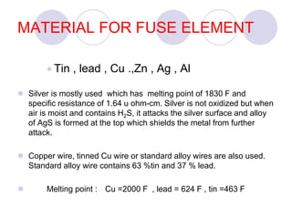
1. A fuse element melts when current exceeds its rating, opening the circuit.
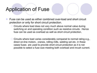
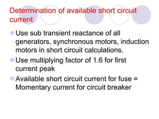
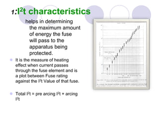
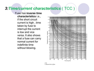
2. Fuses are rated based on their current and time-current characteristics to provide coordinated protection across a system.
3. Proper fuse selection and coordination is necessary to clear faults while preventing unnecessary operations and minimizing stress on system components.