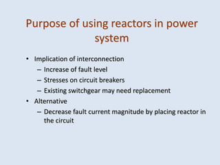
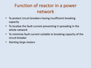
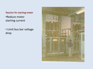
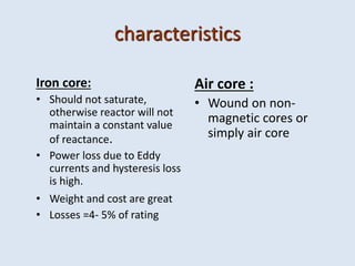
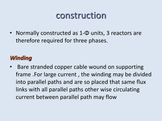
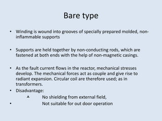
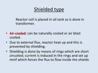
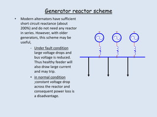
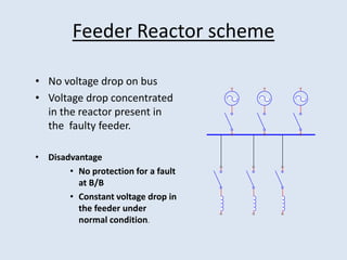
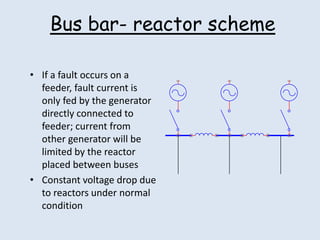
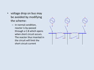
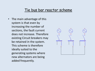
2. Purpose of using reactors in power
system
• Implication of interconnection
– Increase of fault level
– Stresses on circuit breakers
– Existing switchgear may need replacement
• Alternative
– Decrease fault current magnitude by placing reactor in
the circuit
3. Function of reactor in a power
network
• To protect circuit breakers having insufficient breaking
capacity
• To localize the fault current preventing it spreading in the
whole network
• To minimize fault current suitable to breaking capacity of the
circuit breaker
• Starting large motors
4. Reactor for starting motor
•Reduce motor
starting current
• Limit bus bar voltage
drop
5. characteristics
Iron core:
• Should not saturate,
otherwise reactor will not
maintain a constant value
of reactance.
• Power loss due to Eddy
currents and hysteresis loss
is high.
• Weight and cost are great
• Losses =4- 5% of rating
Air core :
• Wound on non-
magnetic cores or
simply air core
6. construction
• Normally constructed as 1-Φ units, 3 reactors are
therefore required for three phases.
Winding
• Bare stranded copper cable wound on supporting
frame .For large current , the winding may be divided
into parallel paths and are so placed that same flux
links with all parallel paths other wise circulating
current between parallel path may flow
7. Bare type
• Winding is wound into grooves of specially prepared molded, non-
inflammable supports
• Supports are held together by non-conducting rods, which are
fastened at both ends with the help of non-magnetic casings.
• As the fault current flows in the reactor, mechanical stresses
develop. The mechanical forces act as couple and give rise to
radiant expansion. Circular coil are therefore used; as in
transformers.
• Disadvantage:
No shielding from external field,
• Not suitable for out door operation
8. Shielded type
Reactor coil is placed in oil tank as is done in
transformer.
• Air-cooled: can be naturally cooled or air blast
cooled.
• Due to external flux, reactor heat up and this is
prevented by shielding.
• Shielding is done by means of rings which are short
circuited; current is induced in the rings and set up
mmf which forces the flux to flow inside the shields
9. Location of Reactor
Generator reactor scheme
Feeder reactor scheme
Bus bar reactor scheme
Tie- bus bar reactor scheme
10. Generator reactor scheme
• Modern alternators have sufficient
short circuit reactance (about
200%) and do not need any reactor
in series. However, with older
generators, this scheme may be
useful,
- Under fault condition
large voltage drops and
bus voltage is reduced.
Thus healthy feeder will
also draw large current
and may trip.
• in normal condition
;constant voltage drop
across the reactor and
consequent power loss is
a disadvantage.
11. Feeder Reactor scheme
• No voltage drop on bus
• Voltage drop concentrated
in the reactor present in
the faulty feeder.
• Disadvantage
• No protection for a fault
at B/B
• Constant voltage drop in
the feeder under
normal condition.
12. Bus bar- reactor scheme
• If a fault occurs on a
feeder, fault current is
only fed by the generator
directly connected to
feeder; current from
other generator will be
limited by the reactor
placed between buses
• Constant voltage drop due
to reactors under normal
condition
13. • voltage drop on bus may
be avoided by modifying
the scheme:
– In normal condition,
reactor is by-passed
through a C.B which opens
when short circuit occurs.
The reactor thus inserted in
the circuit will limit the
short circuit current
14. Tie bus bar reactor scheme
• The main advantage of this
system is that even by
increasing the number of
sections, the fault current
does not increase. Therefore
existing Circuit breakers may
be retained in the system.
This scheme is therefore
ideally suited to the
generating systems where
new alternators are being
added frequently.
16. Short circuit capacity of a bus
• Suppose a short circuit occurs at bus , voltage will reduce to
zero at that bus bar.
• The voltages of healthy buses will also drop and the
amount of reduction in voltage on a healthy Bus will
indicate bus strength
• By the strength of a bus, we mean the ability of a bus to
maintain its voltage when a fault takes place at some
other bus in the network.
• Short circuit capacity of a bus is defined as “the product of
the magnitude of pre fault voltage and post fault current”.
The higher the s.c capacity ,the greater is the strength of a
bus bar and lower will be the impedance seen between a
faulty bus and zero potential of the system.
• Therefore, Infinite bus Is one that is infinitely strong
having infinite short circuit capacity and zero equivalent
impedance
17. Short circuit capacity of breakers
• The breaker has to interrupt high short circuit
currents and when their contacts open, the
voltage across them is the recovery voltage
which is usually 1.0 p.u. Therefore breakers
are rated for short circuit capacity rather than
short circuit current.