Downloaded 269 times


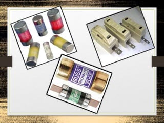


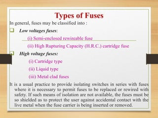

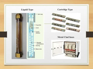
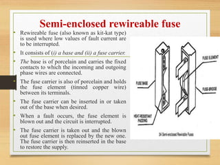
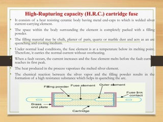
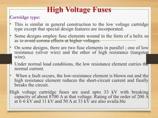
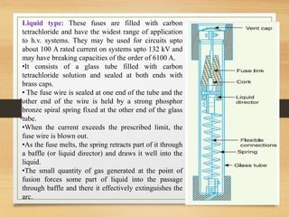


Fuses are the simplest and cheapest form of protection used to interrupt electrical circuits during short circuits or overloads. They work by melting a fuse element made of materials with low melting points like silver or copper. Different types of fuses are used for low and high voltages. Low voltage fuses include semi-enclosed rewireable fuses and high rupturing capacity cartridge fuses. High voltage fuses include cartridge types, which may have two parallel elements, liquid types immersed in carbon tetrachloride, and metal clad oil-immersed fuses used as substitutes for oil circuit breakers in very high voltage applications.


