This document provides an overview of fuse characteristics including:
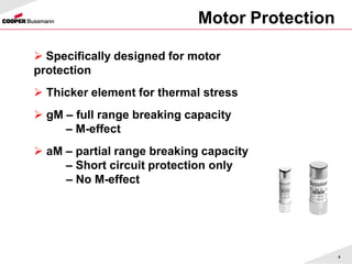
- Different protection classes like general purpose, motor protection, and high speed fuses.
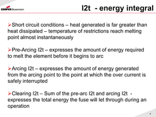
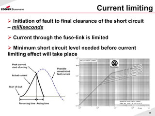
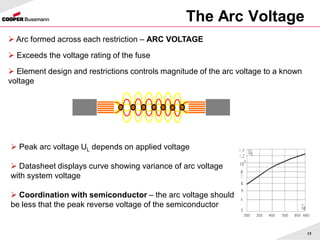
- Time current curves and I2t values that define a fuse's current limiting capability.
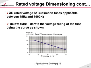
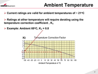
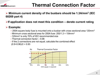
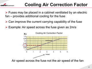
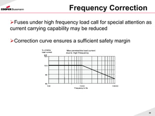
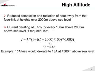
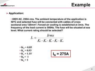
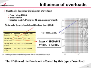
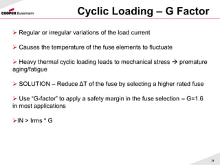
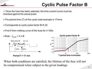
- Factors that influence fuse dimensioning like rated voltage, current derating due to ambient temperature, and overload conditions.
- Guidelines for selecting an appropriately rated fuse for an application taking into account installation details, load characteristics, and environmental conditions.