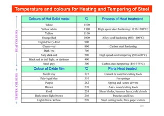
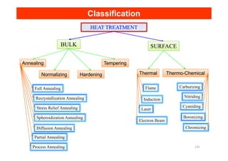
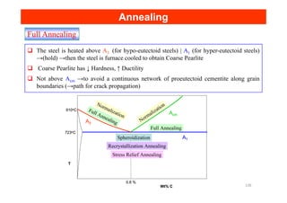
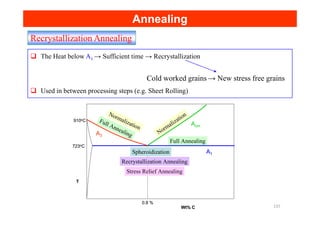
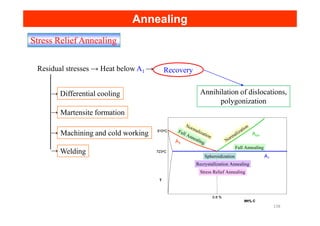
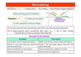
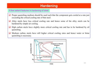
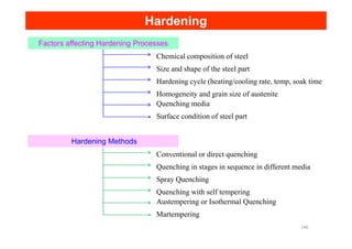
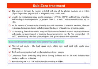
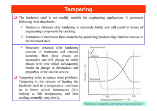
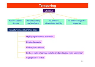
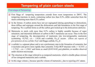
This document discusses various heat treatment processes for steel including annealing, normalizing, hardening, and tempering. It provides details on the purposes, methods, and effects of each process. Full annealing involves heating above A3 and furnace cooling to obtain coarse pearlite and reduce hardness and increase ductility. Normalizing is done above A1 and involves air cooling, resulting in a finer pearlite structure than annealing. Hardening involves heating above A1, quenching to form martensite, and tempering to achieve the desired hardness. Retained austenite that remains after heat treatment can impact properties. Sub-zero treatment below 0°C can help eliminate retained austenite and further increase hardness.
Thanx to see our report again, this time we talked every single information about steel just like properties and manufacturing, advantages and disadvantages, properties with classification of steel. So if you have any questions or you notice mistakes you can send a message to me to this email
Alirizgar234@gmail.com
Dear All, Best Greetings! This presentation is very useful to all of you to understand the steel basics, background, history, steel making process video, characteristics, metallurgical properties, iron carbon diagram, different phases in steel, effects of alloying elements, high carbon steel introduction, and application of low, medium and high carbon steel.
One of the amazing things about steel is all of the forms and qualities it can take on. Of these, stainless steel is incredibly popular due to its corrosion resistance combined with its strength and formability. At Pacesetter, stainless steel is one of the major products we process and distribute. As such, it’s a product we know a lot about, and seek to educate our partners on as well.
So, what is stainless steel?
Duplex stainless steel is a type of stainless steel that is composed of grains of two types of stainless steel material, austenitic and ferritic. The word "duplex" refers to the two-phase micro structure of ferritic and austenitic steel grains.
Replacement of lead Free Cutting Steel - 2018 research paperMukesh Karnik
this project is to study about free cutting steels and machinability property and to focus on newly developed Lead Free- Free Cutting Steel.
Points are given below about project:-
And also explained about Built up edge - Chip Formation to increase the machinability.
effect of alloying elements on free cutting steel.
manufacturing process of free cutting steel.
BASED ON CHROMIUM AND CARBON ADDITION.
To avoid Lead Hazardous problem and environmental friendly.
Stainless steels are alloy steels with a nominal chromium (Cr) content of at least 11 weight percent (wt %), with or without other alloy additions. The oxidation and corrosion resistance of these alloy steels are attributed to the presence of a passive chromium-rich oxide film on the surface. The chromium-rich oxide can be damaged, but will quickly reform if oxygen is available. When exposed to conditions that damage the passive oxide film, stainless steels are subject to corrosive attack.
The rate at which a stainless steel develops a passive film in the atmosphere depends on its chromium content. Polished stainless steels remain bright and tarnish-free under most atmospheric conditions. Exposure to elevated temperatures increases the thickness of the oxide film.
Heat treatment 1 By
P.SENTHAMARAI KANNAN,
ASSISTANT PROFESSOR ,
DEPARTMENT OF MECHANICAL ENGINEERING,
KAMARAJ COLLEGE OF ENGINEERING AND TECHNOLOGY,
VIRUDHUNAGAR, TAMILNADU.
INDIA.
this ppt is useful for understanding the concept of heat treatment process in steel.
it gives the idea about the various stages of heat treatment process in details
Vaccine management system project report documentation..pdfKamal Acharya
The Division of Vaccine and Immunization is facing increasing difficulty monitoring vaccines and other commodities distribution once they have been distributed from the national stores. With the introduction of new vaccines, more challenges have been anticipated with this additions posing serious threat to the already over strained vaccine supply chain system in Kenya.
COLLEGE BUS MANAGEMENT SYSTEM PROJECT REPORT.pdfKamal Acharya
The College Bus Management system is completely developed by Visual Basic .NET Version. The application is connect with most secured database language MS SQL Server. The application is develop by using best combination of front-end and back-end languages. The application is totally design like flat user interface. This flat user interface is more attractive user interface in 2017. The application is gives more important to the system functionality. The application is to manage the student’s details, driver’s details, bus details, bus route details, bus fees details and more. The application has only one unit for admin. The admin can manage the entire application. The admin can login into the application by using username and password of the admin. The application is develop for big and small colleges. It is more user friendly for non-computer person. Even they can easily learn how to manage the application within hours. The application is more secure by the admin. The system will give an effective output for the VB.Net and SQL Server given as input to the system. The compiled java program given as input to the system, after scanning the program will generate different reports. The application generates the report for users. The admin can view and download the report of the data. The application deliver the excel format reports. Because, excel formatted reports is very easy to understand the income and expense of the college bus. This application is mainly develop for windows operating system users. In 2017, 73% of people enterprises are using windows operating system. So the application will easily install for all the windows operating system users. The application-developed size is very low. The application consumes very low space in disk. Therefore, the user can allocate very minimum local disk space for this application.
Student information management system project report ii.pdfKamal Acharya
Our project explains about the student management. This project mainly explains the various actions related to student details. This project shows some ease in adding, editing and deleting the student details. It also provides a less time consuming process for viewing, adding, editing and deleting the marks of the students.
Cosmetic shop management system project report.pdfKamal Acharya
Buying new cosmetic products is difficult. It can even be scary for those who have sensitive skin and are prone to skin trouble. The information needed to alleviate this problem is on the back of each product, but it's thought to interpret those ingredient lists unless you have a background in chemistry.
Instead of buying and hoping for the best, we can use data science to help us predict which products may be good fits for us. It includes various function programs to do the above mentioned tasks.
Data file handling has been effectively used in the program.
The automated cosmetic shop management system should deal with the automation of general workflow and administration process of the shop. The main processes of the system focus on customer's request where the system is able to search the most appropriate products and deliver it to the customers. It should help the employees to quickly identify the list of cosmetic product that have reached the minimum quantity and also keep a track of expired date for each cosmetic product. It should help the employees to find the rack number in which the product is placed.It is also Faster and more efficient way.
About
Indigenized remote control interface card suitable for MAFI system CCR equipment. Compatible for IDM8000 CCR. Backplane mounted serial and TCP/Ethernet communication module for CCR remote access. IDM 8000 CCR remote control on serial and TCP protocol.
• Remote control: Parallel or serial interface.
• Compatible with MAFI CCR system.
• Compatible with IDM8000 CCR.
• Compatible with Backplane mount serial communication.
• Compatible with commercial and Defence aviation CCR system.
• Remote control system for accessing CCR and allied system over serial or TCP.
• Indigenized local Support/presence in India.
• Easy in configuration using DIP switches.
Technical Specifications
Indigenized remote control interface card suitable for MAFI system CCR equipment. Compatible for IDM8000 CCR. Backplane mounted serial and TCP/Ethernet communication module for CCR remote access. IDM 8000 CCR remote control on serial and TCP protocol.
Key Features
Indigenized remote control interface card suitable for MAFI system CCR equipment. Compatible for IDM8000 CCR. Backplane mounted serial and TCP/Ethernet communication module for CCR remote access. IDM 8000 CCR remote control on serial and TCP protocol.
• Remote control: Parallel or serial interface
• Compatible with MAFI CCR system
• Copatiable with IDM8000 CCR
• Compatible with Backplane mount serial communication.
• Compatible with commercial and Defence aviation CCR system.
• Remote control system for accessing CCR and allied system over serial or TCP.
• Indigenized local Support/presence in India.
Application
• Remote control: Parallel or serial interface.
• Compatible with MAFI CCR system.
• Compatible with IDM8000 CCR.
• Compatible with Backplane mount serial communication.
• Compatible with commercial and Defence aviation CCR system.
• Remote control system for accessing CCR and allied system over serial or TCP.
• Indigenized local Support/presence in India.
• Easy in configuration using DIP switches.
Final project report on grocery store management system..pdfKamal Acharya
In today’s fast-changing business environment, it’s extremely important to be able to respond to client needs in the most effective and timely manner. If your customers wish to see your business online and have instant access to your products or services.
Online Grocery Store is an e-commerce website, which retails various grocery products. This project allows viewing various products available enables registered users to purchase desired products instantly using Paytm, UPI payment processor (Instant Pay) and also can place order by using Cash on Delivery (Pay Later) option. This project provides an easy access to Administrators and Managers to view orders placed using Pay Later and Instant Pay options.
In order to develop an e-commerce website, a number of Technologies must be studied and understood. These include multi-tiered architecture, server and client-side scripting techniques, implementation technologies, programming language (such as PHP, HTML, CSS, JavaScript) and MySQL relational databases. This is a project with the objective to develop a basic website where a consumer is provided with a shopping cart website and also to know about the technologies used to develop such a website.
This document will discuss each of the underlying technologies to create and implement an e- commerce website.
Automobile Management System Project Report.pdfKamal Acharya
The proposed project is developed to manage the automobile in the automobile dealer company. The main module in this project is login, automobile management, customer management, sales, complaints and reports. The first module is the login. The automobile showroom owner should login to the project for usage. The username and password are verified and if it is correct, next form opens. If the username and password are not correct, it shows the error message.
When a customer search for a automobile, if the automobile is available, they will be taken to a page that shows the details of the automobile including automobile name, automobile ID, quantity, price etc. “Automobile Management System” is useful for maintaining automobiles, customers effectively and hence helps for establishing good relation between customer and automobile organization. It contains various customized modules for effectively maintaining automobiles and stock information accurately and safely.
When the automobile is sold to the customer, stock will be reduced automatically. When a new purchase is made, stock will be increased automatically. While selecting automobiles for sale, the proposed software will automatically check for total number of available stock of that particular item, if the total stock of that particular item is less than 5, software will notify the user to purchase the particular item.
Also when the user tries to sale items which are not in stock, the system will prompt the user that the stock is not enough. Customers of this system can search for a automobile; can purchase a automobile easily by selecting fast. On the other hand the stock of automobiles can be maintained perfectly by the automobile shop manager overcoming the drawbacks of existing system.
Democratizing Fuzzing at Scale by Abhishek Aryaabh.arya
Presented at NUS: Fuzzing and Software Security Summer School 2024
This keynote talks about the democratization of fuzzing at scale, highlighting the collaboration between open source communities, academia, and industry to advance the field of fuzzing. It delves into the history of fuzzing, the development of scalable fuzzing platforms, and the empowerment of community-driven research. The talk will further discuss recent advancements leveraging AI/ML and offer insights into the future evolution of the fuzzing landscape.
3. The steel is heated above A3 (for hypo-eutectoid steels) | A1 (for hyper-eutectoid steels)
→(hold) →then the steel is furnace cooled to obtain Coarse Pearlite
Coarse Pearlite has ↓ Hardness, ↑ Ductility
Not above Acm →to avoid a continuous network of proeutectoid cementite along grain
boundaries (→path for crack propagation)
Full Annealing
N
N
Annealing
Annealing
A1
A3
Acm
T
Wt% C
0.8 %
723oC
910oC
Spheroidization
Recrystallization Annealing
Stress Relief Annealing
Full Annealing
Full Annealing Normalization
Normalization
A1
A3
Acm
T
Wt% C
0.8 %
723oC
910oC
Spheroidization
Recrystallization Annealing
Stress Relief Annealing
Full Annealing
Full Annealing Normalization
Normalization
136
4. Recrystallization Annealing
The Heat below A1 → Sufficient time → Recrystallization
Used in between processing steps (e.g. Sheet Rolling)
Cold worked grains → New stress free grains
No
No
Annealing
Annealing
A1
A3
Acm
T
Wt% C
0.8 %
723oC
910oC
Spheroidization
Recrystallization Annealing
Stress Relief Annealing
Full Annealing
Full Annealing Normalization
Normalization
A1
A3
Acm
T
Wt% C
0.8 %
723oC
910oC
Spheroidization
Recrystallization Annealing
Stress Relief Annealing
Full Annealing
Full Annealing Normalization
Normalization
137
5. Stress Relief Annealing
Annihilation of dislocations,
polygonization
Differential cooling
Martensite formation
Residual stresses → Heat below A1 → Recovery
→
→
Annealing
Annealing
Welding
Machining and cold working
Martensite formation
→
→
→
A1
A3
Acm
T
Wt% C
0.8 %
723oC
910oC
Spheroidization
Recrystallization Annealing
Stress Relief Annealing
Full Annealing
Full Annealing Normalization
Normalization
A1
A3
Acm
T
Wt% C
0.8 %
723oC
910oC
Spheroidization
Recrystallization Annealing
Stress Relief Annealing
Full Annealing
Full Annealing Normalization
Normalization
138
6. Spheroidization Annealing
Heat below/above A1 (Prolonged holding*)
Cementite plates → Cementite spheroids → ↑ Ductility
Used in high carbon steel requiring extensive machining prior to final hardening and
tempering
Driving force is the reduction in interfacial energy
Annealing
Annealing
The spheroidized structure is desirable when minimum hardness, maximum ductility, or(in
high-carbon steels) maximum machinability is important.
Low-carbon steels are seldom spheroidized for machining, because in the spheroidized
condition they are excessively soft and “gummy”.
Medium-carbon steels are sometimes spheroidization annealed to obtain maximum
ductility.
*If the steel is kept too long at the spheroidized-annealing temperature, the cementite
particles will coalesce and become elongated thus reducing machinability 139
7. Diffusion Annealing
Annealing
Annealing
This process also known as homogenizing annealing, is employed to remove any structural
non-uniformity.
Dendrites, columnar grains and chemical inhomogeneities are generally observed in the
case of ingots, heavy plain carbon steel casting, and high alloy steel castings. These defects
promote brittleness and reduce ductility and toughness of steel.
In diffusion annealing treatment, steel is heated sufficiently above the upper critical
temperature (say, 1000-1200°C), and is held at this temperature for prolonged periods,
usually 10-20 hours, followed by slow cooling.
Segregated zones are eliminated and a chemically homogeneous coarse grain steel is
obtained by this treatment as a result of diffusion.
The coarse grained structure can be refined either by plastic working for ingots or by
employing a second heat treatment for castings.
Hypoeutectoid and eutectoid steel castings are given full annealing treatment, whereas
hypereutectoid steel castings are either normalized or partially annealed for this purpose.
140
9. Partial Annealing
Annealing
Annealing
Partial annealing is also referred to as intercritical annealing or incomplete annealing. In this
process, steel is heated between the A1 and the A3 or Acm. It is followed by slow cooling.
Generally, hypereutectoid steels are subjected to this treatment. Resultant microstructure
consists of fine pearlite and cementite. The reason for this is that grain refinement takes
place at a temperature of about 10 to 30°C above Ac1 for hypereutectoid steels.
As low temperature are involved in this process, so it is cost effective than full annealing
Process Annealing
Process Annealing
In this treatment steel is heated to a temperature below the lower critical temperature, and is
held at this temperature for sufficient time and then cooled. Since it is a subcritical
annealing, cooling rate is of little importance
The purpose of this treatment is to reduce hardness and to increase ductility of cold-worked
steel so that further working may be carried out easily. It is an Intermediate operation and is
sometimes referred to as in process annealing. The process is less expensive than
Recrystallization annealing.
142
10. Heat above
Heat above A
A3
3 |
| A
Acm
cm → Austenization → Air cooling → Fine Pearlite (
→ Austenization → Air cooling → Fine Pearlite (Higher hardness)
Higher hardness)
To reduce segregation in casting or forgings
Refine grain structure prior to hardening
To harden the steel slightly
Purposes A1
A3
Acm
T
Wt% C
0.8 %
723oC
910oC
Spheroidization
Recrystallization Annealing
Stress Relief Annealing
Full Annealing
Full Annealing Normalization
Normalization
A1
A3
Acm
T
Wt% C
0.8 %
723oC
910oC
Spheroidization
Recrystallization Annealing
Stress Relief Annealing
Full Annealing
Full Annealing Normalization
Normalization
In hypo-eutectoid steels normalizing is done 50oC above the annealing temperature
Normalizing
Normalizing
In hypo-eutectoid steels normalizing is done 50 C above the annealing temperature
In hyper-eutectoid steels normalizing done above Acm → due to faster cooling
cementite does not form a continuous film along GB
Annealed Normalized
Less hardness, tensile strength and toughness Slightly more hardness, tensile strength and toughness
Pearlite is coarse and usually gets resolved by
the optical microscope
Pearlite is fine and usually appears unresolved with
optical microscope
Grain size distribution is more uniform Grain size distribution is slightly less uniform
Internal stresses are least Internal stresses are slightly more
Annealed Vs Normalized
143
11. Heat above A3 | Acm → Austenization → Quench (higher than critical cooling rate)
Certain applications demand high tensile strength and hardness values so that the
components may be successfully used for heavy duty purposes. High tensile strength and
hardness values can be obtained by a processes known as Hardening.
hardening process consists of four steps. The first step involves heating the steel to above
A3 temperature for hypoeutectoid steels and above A1 temperature for hypereutectoid steels
by 500C.
The second step involves holding the steel components for sufficient socking time for
homogeneous austenization.
Hardening
Hardening
homogeneous austenization.
The third step involves cooling of hot steel components at a rate just exceeding the critical
cooling rate of the steel to room temperature or below room temperature.
The final step involves the tempering of the martensite to achieve the desired hardness.
Detailed explanation about tempering is given in the subsequent sections. In this hardening
process, the austenite transforms to martensite. This martensite structure improves the
hardness.
In the hardening process, which involves quenching and tempering. During quenching outer
surface is cooled quicker than the center. In other words the transformation of the austenite
is proceeding at different rates. Hence there is a limit to the overall size of the part in this
hardening process. 144
12. A few salient features in hardening of steel
Hardening
Hardening
Proper quenching medium should be used such that the component gets cooled at a rate just
exceeding the critical cooling rate of that steel.
Alloy steels have less critical cooling rate and hence some of the alloy steels can be
hardened by simple air cooling.
High carbon steels have slightly more critical cooling rate and has to be hardened by oil
quenching.
Medium carbon steels have still higher critical cooling rates and hence water or brine
quenching is necessary.
145
13. Hardening
Hardening
Factors affecting Hardening Processes
Chemical composition of steel
Size and shape of the steel part
Hardening cycle (heating/cooling rate, temp, soak time
Homogeneity and grain size of austenite
Quenching media
Surface condition of steel part
Hardening Methods
Conventional or direct quenching
Quenching in stages in sequence in different media
Spray Quenching
Quenching with self tempering
Austempering or Isothermal Quenching
Martempering
146
14. Retained Austenite
Retained Austenite
Austenite that is present in in the ferrous alloys even after the completion of the heat
treatment process is referred to as retained austenite. In simple words, retained austenite is
the untransformed austenite.
Austenite transforms to martensite between Ms and Mf temperatures as it is essentially an
athermal transformation. However, this transformation never goes to completion, i.e., 100%
martensite (Mf temperature line is illustrated as dotted line in TTT diagrams).
This is because at Mf , a small amount of (~1%) of austenite is present in highly stressed
state along with ~99% martensite, and can not transform to martensite because unfavourable
stress conditions.
Both Ms and Mf temperatures decrease with increase in carbon content. Therefore amount of
retained austenite in hardened steels increase with increase in carbon content.
All alloying elements, except Al and Co, lower the Ms temperature and hence enhance the
amount of retained austenite. Therefore, both high carbon steels and high alloy steels are
more prone to the presence of retained austenite.
The substructure of retained austenite differs from that of the original austenite as it has as a
higher density of imperfections like dislocations, stacking faults, etc. which are created by
local plastic deformation of the austenite by martensite crystals.
Tool steels may have retained- austenite in the range of 5-35%. At the surface of a quenched
steel, that restrains are minimum. R.A is less at surface than center of the part. 147
15. Retained Austenite
Retained Austenite
Advantages
Ductility of austenite can help to relieve some internal stresses developed due to hardening,
to reduce danger of distortion and cracks. 10% retained austenite along with martensite is
desirable.
The presence of 30-40% retained austenite makes straightening operation of the
components possible after hardening. Straightening increases the hardness slightly.
Non-distorting steels owe their existence to retained austenite. Here enough austenite is
retained to balance the transformational contracting during heating, on the formation of
austenite from ferrite carbide aggregate on the one hand, and the expansion corresponding
disadvantages
austenite from ferrite carbide aggregate on the one hand, and the expansion corresponding
to the formation of martensite during cooling, on the other, Here, the basis of dimensional
stability of non-distorting steels is the presence of retained austenite.
The soft austenite if present, in large amounts, decreases the hardness of hardened steels.
As retained austenite may transform to lower bainite, or to martensite, there takes place
increase in dimensions of the part. Not only it creates problems in precision gauges, or dies,
the neighboring parts may be put under stress by it. In the component itself, stresses may be
created to cause distortion or cracking.
Retained austenite decreases the magnetic properties of the steel. 148
16. Sub
Sub-
-Zero treatment
Zero treatment
The retained austenite is generally undesirable, sub-zero treatment is one of the method to
eliminate retained austenite.
As the room temperature lies between Ms and Mf temperatures of steel, quenching to room
temperature results in retained austenite.
Subzero treatment consists in cooling the hardened steel to a temperature below 0°C. The
temperature of the sub zero treatment depends on the position of Mf temperature of the
steel.
A steel can be cooled much below the Mf temperature, but it, evidently achieves nothing,
because it cannot bring about any additional increase of hardness, or any additional increase
of martensite, because the Martensitic transformation ends at Mf temperature.
Sub-zero treatment is more effective, if it is carried out immediately after quenching
operation. Any lapse of time between hardening and the cold treatment causes the
stabilization of austenite, makes the retained austenite resistant to further transformation.
Most steels can be cooled by subzero treatment in a low cooling unit with one of the
mediums as given in table (next page) .
The low-cooling unit consists of two vessels, the interior one of copper, where the parts or
tools to be deep frozen, are placed and the exterior one of steel provided with a good heat
insulation.
149
17. Sub
Sub-
-Zero treatment
Zero treatment
Coolant
Minimum
temperature °
°
°
°C
Dry ice (solid Co2)
+ Acetone
-78
Ice + Salt (NaCl) -23
Ice + Salt (CaCl2) -55
Liquid air -183
Liquid Nitrogen -196
Table : Subzero Coolants with
Temperature of Application
Liquid Nitrogen -196
Liquid Pentane -129
Freon -111
Figure : Liquid cooled (liquid N2 ) system.
Components are immersed in a bath of
alcohol, or trichloro ethylene, which is cooled
by a submerged liquid nitrogen spray (-150°C
), cooling rates can be controlled.
150
18. The space in between the vessels is filled with one of the chosen medium, or a system
(figure in previous page) which is inexpensive and can be used.
Usually the temperature range used is in range of -30°C to -150°C, and total time of cooling
and holding at that temperature (Mf) varies from ½ - 1 hour. The hardness increased by 2-4
HRc.
As the amount of martensite increases by sub-zero treatment, it increases hardness, abrasion
resistance, fatigue resistance and eliminates the danger of developing grinding cracks.
As the newly formed martensite may add further to unfavorable stresses to cause distortion
and cracks, the complicated, or intricate shaped components may be first tempered at 150-
Sub
Sub-
-Zero treatment
Zero treatment
and cracks, the complicated, or intricate shaped components may be first tempered at 150-
160°C immediately after first quenching and then given the sub-zero treatment.
Alloyed tool steels – like high speed steel, which now shall need only single stage
tempering.
Tools and components which need exact dimensions – gauges
Carburized steels, especially alloy steels (having elements like Ni in it) to increase their
hardness and wear resistance
Steels having 0.8 to 1.1%C as hardness increases by 1-3 HRc
Sub-zero treatment has been most extensively used for…!
151
19. Tempering
Tempering
The hardened steel is not readily suitable for engineering applications. It possesses
following three drawbacks.
Martensite obtained after hardening is extremely brittle and will result in failure of
engineering components by cracking.
Formation of martensite from austenite by quenching produces high internal stresses in
the hardened steel.
Structures obtained after hardening
consists of martensite and retained
austenite. Both these phases are
metastable and will change to stable
phases with time which subsequently
results in change in dimensions and
properties of the steel in service.
Tempering helps in reduce these problems.
Tempering is the process of heating the
hardened steel to a temperature maximum
up to lower critical temperature (A1),
soaking at this temperature, and then
cooling, normally very slowly.
Variation in properties with tempering temperature
152
20. Tempering
Tempering
Objective
Relieve Internal
stresses
Restore ductility
and toughness
To improve
dimensional stability
To improve magnetic
properties
Structure in as Quenched state
Highly supersaturated martensite
Retained austenite
Undissolved carbides
Rods, or plates of carbide particles produced during ‘auto-tempering’
Segregation of carbon
153
21. Tempering of plain carbon steels
Tempering of plain carbon steels
First Stage of tempering temperature extends from room temperature to 200°C. The
tempering reactions in steels, containing carbon less than 0.2%, differ somewhat from the
steels containing more than 0.2% carbon.
In the former, if carbon atoms have not yet segregated (during quenching) to dislocations,
these diffuse and segregate around the dislocations and lath boundaries in the first stage of
tempering. No ε-carbide forms as all the carbon gets locked up to the dislocations (defects).
Martensite in steels with more than 0.2% carbon is highly unstable because of super
saturation, and interstitial diffusion of carbon in BCT martensite can occur. Thus in the first
First stage of Tempering
saturation, and interstitial diffusion of carbon in BCT martensite can occur. Thus in the first
stage of tempering, the decomposition of martensite into low-tetragonality martensite
(containing ~0.2%C, c/a ~ 1.014) and ε-carbide, Fe2.4C occurs. (There are reports of
precipitation of eta-carbide, Fe2C and Haggs carbide, Fe2.2C.
ε-carbide is a separate phase and is not a preliminary step in the formation of cementite, but
it nucleates and grows more rapidly than cementite. It has HCP structure with c = 4.33A°, a
= 2.73A°, c/a = 1.58A° and forms as small (0.015-0.02 μm) platelets, or needles observed
under electron microscope.
The structure at this stage referred to as tempered martensite, which is double phase mixture
of low tetragonal martensite and ε-carbide.
In this stage volume ↓ because specific volume of martensite ↓ due to rejecting of C atoms.
154
22. Tempering of plain carbon steels
Tempering of plain carbon steels
Second stage of Tempering
Second Stage of tempering temperature lies between 200-300°C. The amount of retained
austenite in the as-quenched steel depends mainly on the composition of the steel, and the
temperature to which steel is quenched.
In the second stage of tempering retained austenite transforms to lower bainite (the carbide
in bainite is ε-carbide). The matrix in lower bainite is cubic ferrite (c/a = 1), where as in
tempered martensite, the low tetragonal martensite has c/a ~ 1.014
When retained austenite changes to lower bainite, their takes place increase in volume.
Third stage of Tempering
Third Stage of tempering temperature lies between 200-350°C. In this stage of tempering,
ε-carbide dissolves in matrix, and low tetragonal martensite losses its completely its carbon
and thus, the tetragonality to become ferrite .
Cementite forms as rods at interfaces of ε-carbide and matrix, twin boundaries, interlath
boundaries, or original austenite grain boundaries.
During this stage, volume decreases just as in stage one, due to complete loss of
tetragonality. In a 1% carbon steel , the total decrease in length in the first and third stages
in around 0.25%
155
23. Tempering of plain carbon steels
Tempering of plain carbon steels
Fourth stage of Tempering
Fourth Stage of tempering temperature lies between 350-700°C.
Growth and spheroidisation of cementite, as well as recovery and Recrystallization of ferrite
occur. Though the growth of cementite starts above 300°C, its spheroidisation starts above
400°C to 700°C.
Spheroidisation takes place due to reduction in interfacial energy of ferrite-cementite
interfaces. As quenched martensite has high concentration of lattice defects. Though their
annealing out starts in the third stage of tempering, but the cementite precipitates retard the
recovery processes.
recovery processes.
Substantial recovery processes starts occurring only above 400°C. original lathe boundaries
are stable up to 600°C, but above this, these are replaced by equiaxed-ferrite grain
boundaries – the process, which is best described as ‘Recrystallization’.
In the end, the optical microstructure consists of equiaxed ferrite grains with coarse
Spheroidal particles of cementite, and then the structure is called globular pearlite, or
spheroidized cementite.
The structure perhaps is the most stable of all ferrite- cementite aggregates, and is the
softest with highest ductility with best machinability.
156
24. Effect of carbon on Tempering
Effect of carbon on Tempering
Effect of tempering temperature( 1 hour at each temperature) on hardness and reactions
157
25. Tempering of alloy steels
Tempering of alloy steels
The presence of alloying elements, steels can change their nature and properties effectively.
Most common elements (except cobalt) shift the CCT curve to longer times, which
essentially result in the increase of hardenability of the steels, so that pearlitic
transformation can be avoided easily to obtain Martensitic structure, even at a slower trate
of cooling and in thicker parts.
Alloying elements also lower Ms and Mf temperatures, increasing further the amount of
retained austenite. The decomposition of retained austenite on tempering, plays quite a
significant role on the properties of tempered steels, specially having high carbon and high
alloying elements.
Some elements, that are not found in carbides, but are present as solid solution in ferrite, are
Al, Cu, Si, P, Ni, and Zr. Some elements arranged in order of increasing tendency to form
carbides are Mn, Cr, W, Mo, V and Ti. These carbide forming elements retard most
effectively the rate of softening during tempering of the steel.
The first stage of tempering does not appear to be effected by the presence of the alloying
elements. However, most of the alloying elements in steels tends to increase the hardness
after tempering than a plain carbon steel with the same carbon content.
At smaller concentration, they merely retard the tempering processes hence the softening,
particularly at higher temperature (> 500°C), where these elements have good diffusivity to
take part in tempering reactions.
158
26. Tempering of alloy steels
Tempering of alloy steels
When alloy carbides are formed, the drop in hardness during tempering is not only retarded
but is significantly increased. The steel is then said to secondary hardening.
Thus, 0.5% chromium , or less than 0.5% Mo resists softening but secondary hardening is
produced by either 12% chromium, or 2 % Mo.. Stronger the carbide, the more potent is the
secondary hardening.
Effect of increasing chromium in 0.35%C steel on tempering
Effect of increasing Mo on tempering of as
quenched 0.1%C steel 159
27. Tempering of alloy steels
Tempering of alloy steels
Element, such as, silicon dissolves in ε-carbide to stabilize it. Steels with 1-2% silicon have
ε-carbide present even after tempering at 400°C, which means that the formation of
cementite is delayed considerably, and thus, resisting the softening. Otherwise, the effect of
silicon is essentially due to solid solution strengthening.
Nickel has a small, but constant effect on tempered hardness at all temperatures due to solid
solution strengthening as it is not a carbide former.
Manganese has little effect on softening at low tempering temperatures, but at high
temperatures, has a strong effect on due to its faster diffusion then, and thus, it resists
cementite coarsening as it is present in cementite as (Fe, Mn)3C.
Martensite in plain carbon steels losses its tetragonality by 300°C, but the tetragonality is
seen at 450°C, or even at 500°C if the steels have elements like Cr, W, Mo, Ti, V and Si.
The basic cause of steep softening in carbon steels on tempering above 400°C, is the
coagulation of the cementite particles. Alloying elements notably Si, Cr, Mo, V, when
present in steels, retard the coalescence and the coarsening of cementite particles., resulting
in enhanced hardening over and above the solid solution hardening effect.
Elements like Cr, Si, Mo, or W delay coarsening to temperature range of 500-550°C. up to
tempering temperature 500°C, the carbides formed are of iron with proportional alloying
elements in it, but above 500°C, alloying elements can form their own carbides and thus,
coarse cementite particles are replaced by fine dispersion of more stable alloy carbides.
160
28. Tempering of alloy steels
Tempering of alloy steels
An Fe-10 Ni alloy shows constant
hardness on tempering up to 450°C and
then, there takes place some decrease in
strength (curve I).
Addition of 0.12% carbon increases the
as quenched strength to almost double,
and slow decrease of hardness occurs on
tempering to fall to 0.7 GPa at 500°C.
A 8% cobalt addition, which doesn’t
enter the carbide, delays the softening to
have strength of 0.8 GPa at 500°C .
Addition of 2% Cr almost continuously
but slowly ↑ hardness to start falling at
above ~450°C to become 1.1 GPa at
500°C by fine dispersion of Cr carbide.
Addition of Mo causes secondary
hardening, as it is very strong carbide
forming element, to attain a hardness of
1.3 Gpa at 500°C
Effect of C, Co, Cr, and Mo on tempering of
Fe-10Ni steels
161
29. Tempering of alloy steels :
Tempering of alloy steels : Secondary Hardening
In alloy steels, having larger amounts of strong carbide forming elements like Mo, Ti, V,
Nb, W, Cr etc., and carbon , a peculiar phenomena occurs, the hardness of the as-quenched
martensite (called primary hardness) on tempering, decreases initially, as the tempering
temperatures is raised, but starts increasing again to often become higher than the as
quenched hardness, with much improved toughness, when tempered in the range of 500 to
600°C. This increase in hardness is called secondary hardness (also called red hardness).
This is great importance in high speed steels, as these are able to continue machining, at
high speeds (as these are able to resist fall in hardness and thus, the cutting property ) even
when they become red hot.
Secondary hardening is a process, similar to age hardening, in which coarse cementite
particles are replace by a new and much finer alloy carbide dispersion of V4C3, Mo2C, W2C
(which normally form on dislocations). As in aging a critical dispersion causes a peak in the
hardness and strength of the alloy, and as over aging takes place, i.e., carbide dispersion
slowly coarsens, the hardness decreases.
Secondary hardening is best shown in steels containing Mo, V, W, Ti and also in Cr steels at
high chromium concentrations.
The amount of secondary hardening in an alloy steel is directly proportional to the volume
fraction of the alloy carbides, and thus is directly proportional to the concentration of strong
carbide forming elements present in steels. The alloy carbides must precipitate as fine
dispersion in ferrite matrix rather than massive carbide particles. 162
30. Time and Temperature relationship in Tempering
Time and Temperature relationship in Tempering
For a given steel, a heat treater might like to choose some convenient tempering time, say
over night, otherwise different than 1 hour, and thus, wants to calculate the exact
temperature required to achieve the constant hardness.
Hollomon and Jaffe’s “tempering parameter” may be used for this purpose as it relates the
hardness, tempering temperature and tempering time. For a thermally activated process, the
usual rate equation is :
Where, t is the time of tempering to develop a given hardness, and Q is the ‘empirical
activation energy’ . ‘Q’ is not constant in the complex tempering processes but varies with
RT
Q
Ae
t
Rate /
1 −
=
=
activation energy’ . ‘Q’ is not constant in the complex tempering processes but varies with
hardness. Thus, hardness was assumed to be a function of time and temperature:
Interestingly, is a constant, and let it be t0. Equating activation energies of eq (1)
and (2) gives,
As t0 constant then
Where, C is a constant, whose value depends on the composition of austenite. The single
parameter which expresses two variables time and the temperature i.e., T (C + ln t) is called
the Hollomon and Jaffe tempering parameter. (hardness in vickers is preferable)
]
[ / RT
Q
te
f
H −
=
]
[ / RT
Q
te−
[ ] )
(
ln
ln 0 H
f
t
t
T
Q =
−
=
[ ]
)
ln
( t
C
T
f
H +
=
163
31. Temperature and colours for Heating and Tempering of Steel
Colours of Hot Solid metal °
C Process of Heat treatment
White 1500
Yellow white 1300 High speed steel hardening (1230-1300°C)
Yellow 1100
Orange Red 1000 Alloy steel hardening (800-1100°C)
Light-Cherry-Red 900
Cherry-red 800 Carbon steel hardening
Dark-red 700
Vary dark-red 500 High speed steel tempering (500-600°C)
Black red in dull light, or darkness 400
HEAT
COLOURS
Black red in dull light, or darkness 400
Steel gray 300 Carbon steel tempering (150-575°C)
Colour of Oxide film °
C Parts Heat treated
Steel Gray 327 Cannot be used for cutting tools
Pale-light blue 310 For springs
Purple 282 Spring and screw drivers
Brown 270 Axes, wood cutting tools
Gold 258 Shear blades, hammer faces, cold chisels
Dark-straw-light-brown 240 Punches and Dies
Light-Straw-Yellow 220 Steel cutting tools, files, paper cutters
TEMPER
COLOURS
164
32. Embrittlement during Tempering
Embrittlement during Tempering
Normally, as the tempering progresses, the hardness and the strength decreases, but the
ductility and impact strength increase. But in certain steels, there is an unexpected decrease
of the impact strength in certain ranges of temperatures. This indicates that there are two
main types of embrittlement during tempering.
Tempered Martensite Embrittlement (TME)
Temper Embrittlement
Both these embrittlement raise the impact transition temperature (ITT) to higher
temperature. Figure (below) indicates the increase in impact transition temperature, Δ(ITT)
due to TE in SAE 3140 steel.
unembrittled
embrittled
Temper-embrittlement in SAE 3140
steel shifts the impact transition
temperature to higher temperature .
Δ(TTT) indicates the amount of
increase.
165
33. Embrittlement during Tempering
Embrittlement during Tempering
Normally, the degree of both type of embrittlement is expressed in terms of relative
displacements of ITT i.e., by Δ (ITT) illustrated in figure (in previous slide).
In both the transgranular fracture mode is replaced by an intergranular (IG) mode below the
transition temperature, i.e., these show bright inter crystalline fracture along original
austenite grain boundaries.
Inspite of these similar effects, the two types of embrittlement are two separate phenomena,
which occur in two different temperature ranges. Moreover, TME is a much faster process
usually occurring in one hour, where as TE takes many hours.
Temper embrittlement is of mush greater concern from practical point of view, as the rotors
and shafts of power generating equipment even after tempering above 600°C, develop it
when thick section cool very slowly through the range (450-600°C)
Schematic illustration of effect of
tempering temperature on impact
strength in steels prone to
embrittlement during tempering.
166
34. As TME develops after tempering in range 260°C to 370°C, it is called as “350°C”
embrittlement, or 500°F embrittlement. It is called ‘one-step embrittlement’ as during
heating only in this range, TME develops. It is also called ‘irreversible embrittlement
because a steel embrittled by tempering in this range , if heated further to above 400°C
(above the critical range), becomes tougher, and the tempered martensite embrittlement
does not occur again if cooled down to or tempered in the range of 260°C to 370°C again.
All steels, including the plain carbon steels are prone to irreversible embrittlement to some
extent, and that is why tempering range of 260°C- 370°C is avoided in all steels, though it
is a malady of low alloy steels.
The embrittlement is associated with the change in the structure of carbide from epsilon (ε)
Tempered Martensite embrittlement
The embrittlement is associated with the change in the structure of carbide from epsilon (ε)
to cementite in the form of a film at the grain boundaries.
On tempering at higher temperatures, this film disappears and can not be restored, on
repeated heating in 260°C-370°C temperature range.
Although, tempered martensite embrittlement is concurrent with the precipitation of
cementite, but such precipitation is not in itself the cause of loss of impact toughness, as the
embrittlement is does not occur if P, Sb, Sn, As, or N are not present in steel.
Addition of sufficient silicon to the steel inhibits the formation of cementite in the critical
range, as silicon dissolved in epsilon carbide, increases its stability, and thus embrittlement
does not occur
167
35. Temper embrittlement
Temper embrittlement
The sickness of alloy steels occurs when they are tempered in the range 450°C to 600°C. it
is also called reversible embrittlement (as well as two step embrittlement), because it
occurs, when steels are tempered in this range, but gets removed, when heated to high
temperatures, but occurs again on slow continuous cooling through this range from that high
temperature (>600°C). The degree of embrittlement depends on the rate of cooling in the
range 600-450°C.
The phenomena of temper embrittlement results in loss of toughness as measured by
notched impact test (without affecting very much the hardness, Y.S, UTS, elongation and
fatigue properties), and a rise in ductile to brittle transition temperature occurs, with an
intergranular (IG) fracture, below the transition temperature along the original austenitic
grain boundaries.
Carbon steels in general, but with less than 0.5% Mn, do not show temper embrittlement.
Alloy steels of high purity do not show it. It is caused primarily by Sb and P and secondarily
by Sn or As (even in amounts as low as 0.01%) in presence of elements like Ni, Mn, Cr, Si
in steels. The highest effect is in Ni-Cr and Mn-Cr steels. Presence of elements like Mo, Ti,
Zr delay, or remove embrittlement.
The characteristic features of temper embrittlement are best explained by the concept of co-
segregation. The impurity solutes are the surface active elements in iron, i.e., these reduce
the grain boundary energy, and thus reduce the cohesion. Elements like Sb, P, As, Sn,
interact with certain elements like Ni and Mn in steels.
168
36. Temper embrittlement
Temper embrittlement
These interactions leads to co-segregation of alloying elements and the impurity elements
such as between Ni-Sb, Ni-P-Ni-Sn and Mn-Sb. The reason of co-segregation is the stronger
interaction between them than, between either of these and iron.
If the interaction is very strong then, co-segregation does not occur, but a scavenging effect
is got, as happens between Mo-P, Ti-P, which is the cause of elimination of embrittlement
by 0.5% Mo in such steels. If larger amount of Mo, Ti, Zr are present , then these elements
slowly react with carbon to form stable carbides releasing the impurity atoms to segregate to
the boundaries.
Additional segregation may take place, when two alloying elements are present
simultaneously, such as Ni and Cr. At high temperatures (>600°C), thermal vibrations make
the equilibrium segregation low enough not to cause embrittlement., and at lower
temperature (<450°C), the diffusion of the elements is too low to cause enough co-
segregation with in the normal tempering time.
The following methods are normally recommended to minimize the effect of Temper
embrittlement
Keep the impurities such as Sb, P, Sn, As as low as possible
Alloy the steel with Mo (0.5-0.75%)
Quench from tempering at higher temperatures
169
37. Heat Treatment Defects
Heat Treatment Defects
Heat treatment of steels or aluminum can lead to several defects. The principal types of
defects found in quenching of steels are internal and external cracks in the work, distortion
and warping.
CRACK : When the internal tensile stresses exceed the resistance of the steel to separation
the crack occurs. The insertion of the tools in the furnace without preheating for tempering
is one of the main causes of crack propagation. The crack formation is reduced by
preheating the tool between 2000Cto 3000C.
DISTORTION : Distortion occurs due to uneven heating, too fast cooling, part incorrectly
supported in furnace, incorrect dipping in quenching and stresses present before preheating.
Distortion can be prevented by preheating the tool or check furnace capacity, reduce the
hardening temperature, and by reviewing the method of dipping.
WARPING : Asymmetrical distortion of the work is often called warping in heat-treating
practice. Warping is usually observed upon non-uniform heating or over heating for
hardening. It also occurs when the work is quenched in the wrong position and when the
cooling rate is too high in the temperature range of the martensite transformation. An
elimination of these causes should subsequently reduce warping.
The properties required in the heat treated part are obtained without the parts being distorted
beyond the acceptable limits.
The ideal design for a heat treatable part is the shape that when heated (or cooled) would
have the same temperature at every point with in the part. 170