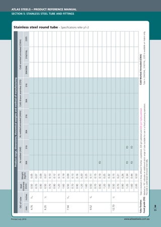
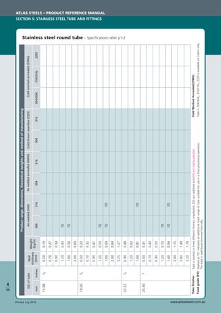
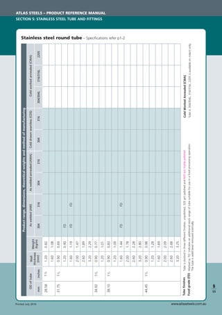
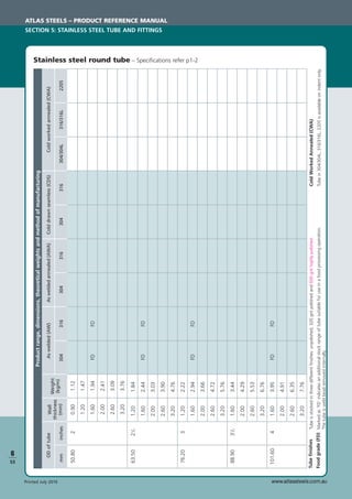
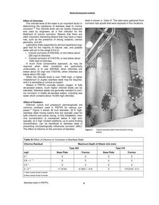
This document serves as a comprehensive guide on stainless steel, detailing its various types, classifications, and applications for design engineers. It outlines critical factors for selecting stainless steel, including corrosion resistance, mechanical properties, fabrication operations, and total cost. The information is a collaboration between the Specialty Steel Industry of North America and the original committee of stainless steel producers, providing a thorough overview of stainless steel's characteristics and guidelines for its effective use.

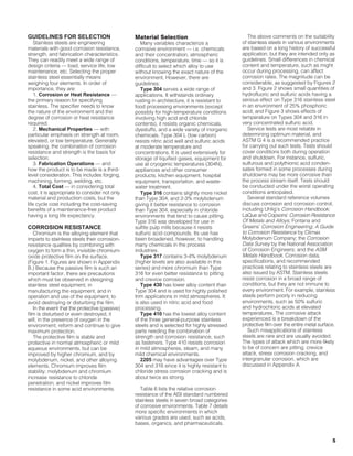


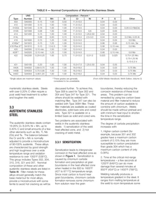
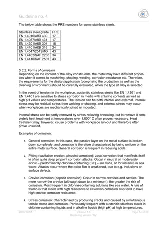
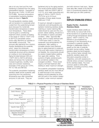
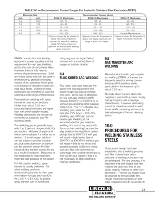
![8
the horizontal axis and the nickel
equivalent (% Ni + 30 x % C + 0.5 x
% Mn) on the vertical axis. Despite
long use, the Schaeffler Diagram is
now outdated because it does not
consider nitrogen effects and
because it has not proven possible to
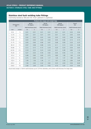
establish agreement among several
measurers as to the ferrite percent in
a given weld metal.
An improvement on the Schaeffler
Diagram is the 1973 WRC-DeLong
Diagram, which can be used to
estimate ferrite level. The main
differences are that the DeLong
Diagram includes nitrogen (N) in the
Ni equivalent (% Ni + 30 x % C x 30
x % N + 0.5 x % Mn) and shows
Ferrite Numbers in addition to
“percent ferrite.” Ferrite Numbers at
low levels may approximate “percent
ferrite.” The most recent diagram,
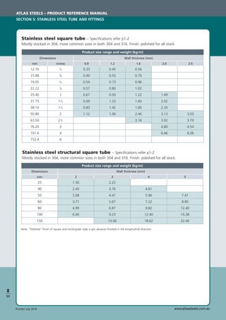
the WRC-1992 Diagram, Figure 2, is
considered to be the most accurate
predicting diagram at present. The
WRC-1992 Diagram has replaced the
WRC-DeLong Diagram in the ASME
Code with publication of the 1994-95
Winter Addendum. Its Ni equivalent
(% Ni + 35 x % C + 20 x % N + 0.25
Cu) and Cr equivalent (% Cr + % Mo
+ 0.7 x % Cb) differ from those of
Schaeffler and WRC-DeLong.
Ferrite Number may be estimated by
drawing a horizontal line across the
diagram from the nickel equivalent
number and a vertical line from the
chromium equivalent number. The
Ferrite Number is indicated by the
diagonal line which passes through
the intersection of the horizontal and
vertical lines.
Predictions by the WRC-1992 and
WRC-DeLong Diagrams for common
grades like 308 are similar, but the
WRC-1992 diagram generally is more
accurate for higher alloy and less
common grades like high manganese
austenitic or duplex ferritic-austenitic
stainless steels.
Ferrite Number can be measured
directly on weld deposits from the
magnetic properties of the ferrite.
Several instruments are available
commercially, including the Magne
Gage, the Severn Gage, the
Inspector Gage and the Ferritescope
which can be calibrated to AWS A4.2
or ISO 8249 and provide readings in
Ferrite Number.
The amount of ferrite normally should
not be greater than necessary to
prevent hot cracking with some
margin of safety. The presence of
ferrite can reduce corrosion
resistance in certain media and
excess ferrite can impair ductility and
toughness.
3.4
PRECIPITATION HARDENING
STAINLESS STEELS
There are three categories of precipi-
tation hardening stainless steels –
martensitic, semiaustenitic and
austenitic.
The martensitic stainless steels can
be hardened by quenching from the
austenitizing temperature [around
1900°F (1038°C)] then aging
between 900 to 1150°F (482 to
621°C). Since these steels contain
less than 0.07% carbon, the marten-
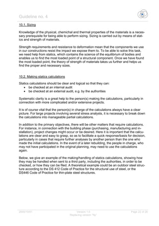
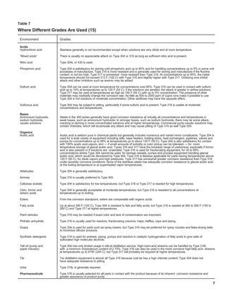
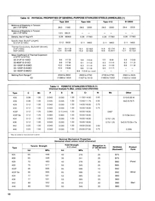
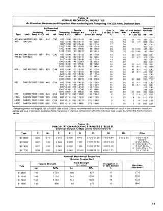
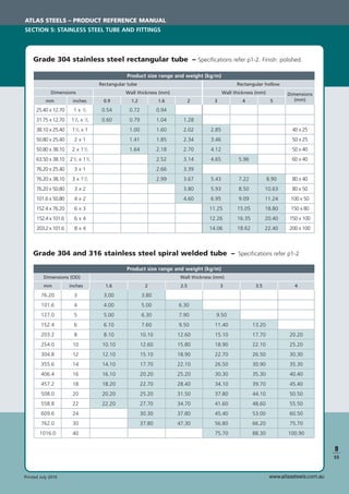
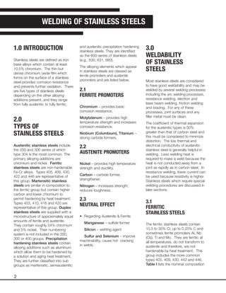
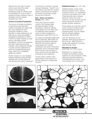
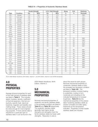
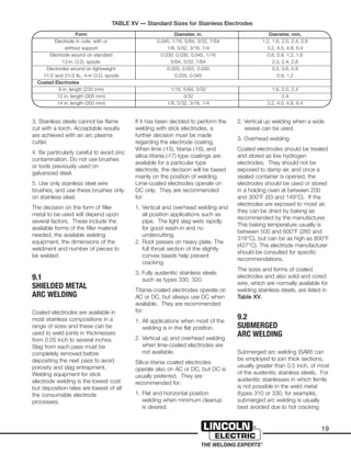
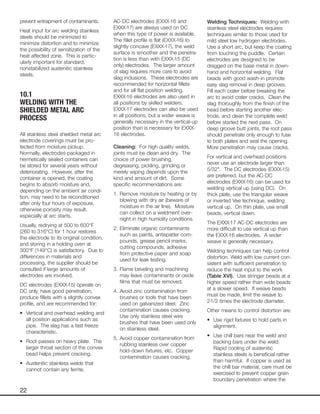
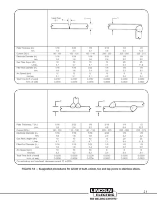
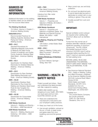
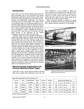
UNS Composition - Percent *
Type Number C Mn Si Cr Ni P S Other
Precipitation-Hardening Types
PH 13-8 Mo S13800 0.05 0.10 0.10 12.25-13.25 7.5-8.5 0.01 0.008 2.0-2.5 Mo;
0.90-1.35 Al; 0.01 N
15-5 PH S15500 0.07 1.00 1.00 14.0-15.5 3.5-5.5 0.04 0.03 2.5-4.5 Cu;
0.15-0.45 Nb(Cb) + Ta
17-4 PH S17400 0.07 1.00 1.00 15.5-17.5 3.0-5.0 0.04 0.03 630 3.0-5.0 Cu;
0.15-0.45 Nb(Cb) + Ta
17-7 PH S17700 0.09 1.00 1.00 16.0-18.0 6.5-7.75 0.04 0.03 631 0.75-1.15 Al
PH 15-7 Mo S15700 0.09 1.00 1.00 14.0-16.0 6.5-7.75 0.04 0.03 2.0-3.0 Mo; 0.75-1.5 Al
17-10 P 0.07 0.75 0.50 17.0 10.5 0.28
A286 S66286 0.08 2.00 1.00 13.5-16.0 24.0-27.0 0.040 0.030 660 1.0-1.5 Mo; 2 Ti; 0.3 V
AM350 S35000 0.07-0.11 0.5-1.25 0.50 16.0-17.0 4.0-5.0 0.04 0.03 2.5-3.25 Mo; 0.07-0.13 N
AM355 S35500 0.10-0.15 0.5-1.25 0.50 15.0-16.0 4.0-5.0 0.04 0.03 2.5-3.25 Mo
AM363 0.04 0.15 0.05 11.0 4.0 0.25 Ti
Custom 450 S45000 0.05 1.00 1.00 14.0-16.0 5.0-7.0 0.03 0.03 1.25-1.75 Cu; 0.5-1.0 Mo
8 x %C - Nb(Cb)
Custom 455 S45500 0.05 0.50 0.50 11.0-12.5 7.5-9.5 0.04 0.03 0.5 Mo; 1.5-2.5 Cu;
0.8-1.4 Ti; 0.1-0.5 Nb(Cb)
Stainless W S17600 0.08 1.00 1.00 16.0-17.5 6.0-7.5 0.04 0.03 0.4 Al; 0.4-1.2 Ti
Duplex Types
2205 S32205 0.03 2.0 1.0 22.0 5.5 0.03 0.02 3.0 Mo; 0.18 N
2304 S32304 0.03 2.5 1.0 23.0 4.0 0.1 N
255 0.04 1.5 1.0 25.5 5.5 3.0 Mo; 0.17 N; 2.0 Cu
NU744LN 0.067 1.7 0.44 21.6 4.9 2.4 Mo; 0.10 N; 0.2 Cu
2507 S32750 0.03 1.2 0.8 25 5.5 0.035 0.020 4 Mo; 0.28 N
TABLE IV — Nominal Compositions of Precipitation Hardening and Duplex Stainless Steels
*Single values are maximum values. (From ASM Metals Handbook, Ninth Edition, Volume 3) and ASTM A638
ASTM
A
GRADE](https://image.slidesharecdn.com/stainlesssteelpiping-171128025757/85/Stainless-steel-piping-44-320.jpg)


![Stainless steel in PWTPs
Nickel Development Institute
• Use mechanical connections on joints where heat
tint oxide removal is not practical.
Other minimum fabrication requirements should include
the following:
• Proof of acceptable welding procedure
specifications for the work to be performed and
verified welder performance qualifications. The
engineer and/or customer should review and verify
both. Suggested guides are ASME Section IX and
AWS B2.1.
• Require full penetration welds, free of cracks,
overlaps and cold laps.
• Limit misalignment for manual welds to 1/16 in. (1.6
mm) or half the wall thickness, whichever is less.
Automatic orbital welding procedures are usually
more restrictive on misalignment.
• Limit on weld reinforcement and concave root
(11/16 in. [1.6 mm]), or to agreed-upon limits.
• Limit on undercut, e.g. 1/32 in. (0.8 mm) or 10%
of base metal thickness, whichever is less.
• Provide for secure end closures and leave in place
until final assembly.
• Provide for prompt and complete drainage of the
piping systems after hydrostatic testing.
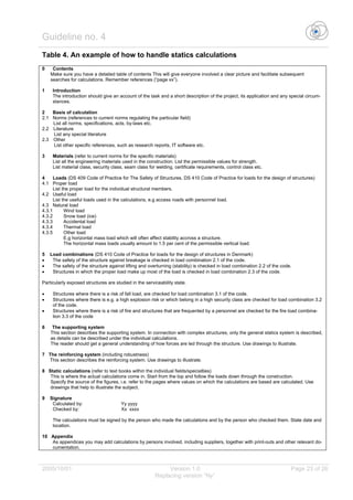
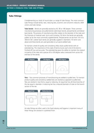
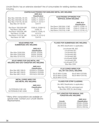
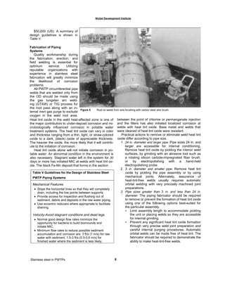
Post-Fabrication Cleaning
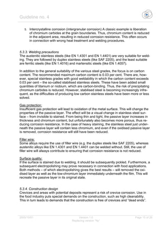
Embedded free iron on stainless steel surfaces causes
rust marks to form and in some instances provides the sites
for the initiation of corrosion.(5)
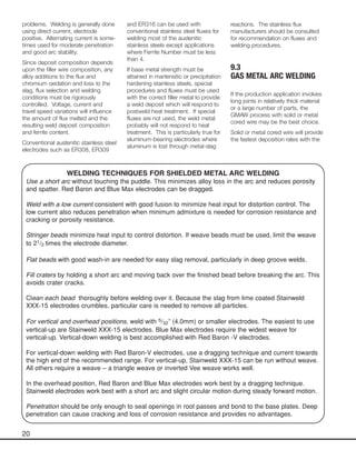
Figure 5 shows the devel-
opment of rust at a weld brushed with a carbon steel wire
brush; only stainless steel wire brushes should be used.
Nitric acid and other "passivation" treatments described in
ASTM A380 are not fully effective in removing iron and other
surface defects. Pickling with nitric-hydrofluoric acid
removes free iron and a thin surface layer of metal that may
contain surface defects; the metal surface is then passive
and in the most corrosion-resistant state. If a
nitric-hydrofluoric acid pickle is not practical, the free iron
can be removed mechanically. Acceptable methods include
the use of medium to fine-grit abrasives such as clean flap-
per wheels, flexible disks, or blasting with clean abrasives
such as glass beads, garnet, or walnut shells. Free iron and
heat tint oxide can also be removed by a hand-held
electropolishing probe.
The water wetting and drying procedure described in
ASTM A380 is a very effective test to check for the removal
of free iron. The procedure calls for wetting the surface with
distilled or deionized water or fresh water followed by drying.
After the wet-dry cycles, the surface should show no
evidence of rust stains or other corrosion products. The
ferroxyl test for free iron described in A380 is even more
sensitive but may not be acceptable for use in potable water
systems.
Operations and Maintenance
Failure to drain promptly after hydrostatic testing or
allowing water to remain stagnant in piping or tanks for
extended periods of time has led to MIC. In stagnant water,
bacteria have an opportunity to develop biomounds and
multiply, leading in some instances to MIC at welds where
there is heat tint oxide. Over 90% of the reported instances
of MIC occur in the vicinity of welds. There are occasional
reports of MIC on bare metal away from welds, but these
occurrences seem to be in severe MIC environments. The
following actions avoid MIC even when heat tint oxide is
present.
• Drain promptly and blow dry after hydrostatic testing or
when the system is placed in extended standby.
Alternately, circulate water if draining is not possible.
• Place in service within a few days after hydrostatic
testing and provide for prompt draining should the
system be placed in standby at some future date.
• Slope horizontal runs sufficiently so they will drain
without leaving water between support points.
Other guides for the operation and maintenance of stain
less steel piping systems includes the following practices:
• Establish a schedule to flush out sediment and debris
on horizontal runs of raw water piping.
• During downtime, drain completely and dry or,
alternately, circulate water for one hour daily.
• For the initial disinfecting treatment, dissolve calcium
hypochlorite granules before introducing them into or
onto the surface of stainless steel piping. Calcium
hypochlorite granules dissolve slowly and have
created a severe micropitting environment when
resting on stainless steel.
• Provide proper ventilation to clear chlorine from all
enclosed spaces.
7](https://image.slidesharecdn.com/stainlesssteelpiping-171128025757/85/Stainless-steel-piping-81-320.jpg)