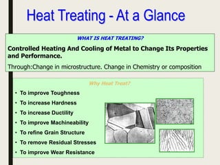
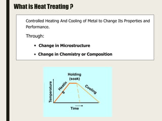
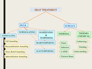
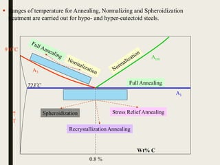
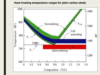
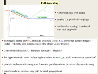
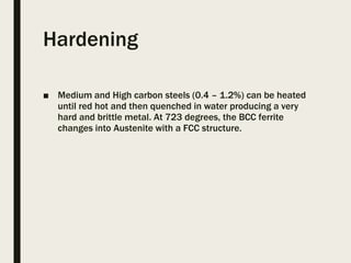
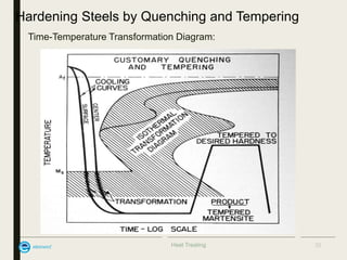
HEATTREATMENT-I
Prepared By
Mr.P.Senthamaraikannan, M.E., (Ph.D).
Assistant professor,
Department of Mechanical engineering,
Kamaraj college of engineering and technology,
Virudhunagar.
WHAT IS HEAT TREATING?
Controlled Heating And Cooling of Metal to Change Its Properties
and Performance.
Through:Change in microstructure. Change in Chemistry or composition
Why Heat Treat?
• To improve Toughness
• To increase Hardness
• To increase Ductility
• To improve Machineability
• To refine Grain Structure
• To remove Residual Stresses
• To improve Wear Resistance
Holding
(soak)
Time
Temperature
What is Heat Treating ?
Controlled Heating And Cooling of Metal to Change Its Properties and
Performance.
Through:
• Change in Microstructure
• Change in Chemistry or Composition
PRINCIPLES OF HEAT TREATMENT – Fe – Carbon Diagram
FERRITE- B C C
AUSTENITE- F C C
MARTENSITE- B C T
TTT Diagrams
FullTTT Diagram
The complete TTT
diagram for an iron-
carbon alloy of eutectoid
composition.
A: austenite
B: bainite
M: martensite
P: pearlite
HEAT TREATMENT
BULK SURFACE
ANNEALING
Full Annealing
Recrystallization Annealing
Stress Relief Annealing
Spheroidization Annealing
AUSTEMPERING
THERMAL THERMO-
CHEMICAL
Flame
Induction
LASER
Electron Beam
Carburizing
Nitriding
Carbo-nitriding
NORMALIZING HARDENING
&
TEMPERING
MARTEMPERING
A1
A3
Acm

T
Wt% C
0.8 %
723C
910C
Spheroidization
Recrystallization Annealing
Stress Relief Annealing
Full Annealing
 Ranges of temperature for Annealing, Normalizing and Spheroidization
treatment are carried out for hypo- and hyper-eutectoid steels.
Heat-treating temperature ranges for plain-carbon steels
Full Annealing
 The steel is heated above A3 (for hypo-eutectoid steels) & A1 (for hyper-eutectoid steels) →
(hold) → then the steel is furnace cooled to obtain Coarse Pearlite.
 Coarse Pearlite has low (↓) Hardness but high (↑) Ductility.
 For hyper-eutectoid steels the heating is not done above Acm to avoid a continuous network of
 proeutectoid cementite along prior Austenite grain boundaries (presence of cementite along
 grain boundaries provides easy path for crack propagation).
A1
A3
Acm

T
Wt% C
0.8 %
723C
910C
Full Annealing
Full Annealing
 A microstructure with coarse
 pearlite (i.e. pearlite having high
 interlamellar spacing) is endowed
with such properties.
Annealing
■ Makes a metal as soft as
possible
■ Hypoeutectoid steels (less
than 0.83% carbon) are
heated above upper critical
temp., soaked and cooled
slowly.
■ Hypereutecoid (above 0.83%)
are heated above lower
critical temp., soaked and
allowed to cool slowly.
■ Process Annealing. Low
carbon steels may
harden through cold
working.They can be
heated to around 100
degrees below lower
critical temp., soaked
and allowed to cool in air.
■ Spheroidising. High
carbon steels may be
annealed just below the
lower critical temp. to
improve machinability.
Morphology of Pearlite
(a) coarse pearlite (b) fine pearlite 3000X
(a) (b)
Recrystallization Annealing
Heat below A1 → Sufficient time → Recrystallization
A1
A3
Acm

T
Wt% C
0.8 %
723C
910C
Recrystallization Annealing
 During any cold working operation (say cold rolling), the material becomes harder
(due to work hardening), but loses its ductility. This implies that to continue
deformation the material needs to be recrystallized (wherein strain free grains
replace the ‘cold worked grains’).
 Hence, recrystallization annealing is used as an intermediate step in (cold)
deformation processing.
 To achieve this the sample is heated below A1 and held there for sufficient time for
recrystallization to be completed.
Strain Hardening Due to Cold Drawing
New yield strength yi higher than initial yield strength, y0.
Reason  strain hardening.
17
Strain Hardening due to Cold Drawing
Yield strength + hardness increased due to strain hardening,
but ductility decreased (material becomes more brittle).
18
Effect of Cold Drawing on Yield strength & Ductility
Recovery, Recrystallization, and Grain Growth
Plastic deformation increases dislocation density +
changes grain size distribution
Therefore, stored strain energy (dislocation strain
fields + grain distortions)
External stress removed: most dislocations, grain
distortions and associated strain energy retained.
Restoration to state before cold-work by heat-
treatment: Recovery and Recrystallization,
followed by grain growth.
Recovery
Heating  increased diffusion
 enhanced dislocation motion
 decrease in dislocation density by annihilation,
formation of low-energy dislocation configurations
 relieves internal strain energy
Some of the mechanisms of dislocation annihilation:
vacancies
slip plane
Edge dislocation
Recrystallization
 After recovery grains can still be strained. Strained grains
 replaced upon heating by strain-free grains with
 low density of dislocations.
 Recrystallization: nucleation and growth of new grains
 Driving force: difference in internal energy between
 strained and unstrained
 Grain growth  short-range diffusion
 Extent of recrystallization depends on temperature and time.
 Recrystallization is slower in alloys
22
Recrystallization –effect of Cold work on temperature
Recrystallization temperature: temperature at which process is
complete in one hour. Typically 1/3 to 1/2 of melting temperature
(can be as high as 0.7 Tm in some alloys).
Recrystallization decreases as %CW is increased. Below "critical deformation",
recrystallization does not occur.
23
Recrystallization
■ To homogenize the structure which is dislocated
due to cold forming & semi hot & Hot forgings
Cold rolled Grain structure Annealed Grain structure
Stress Relief Annealing
Annihilation of dislocations,
polygonization
Welding
Differential cooling
Machining and cold working
Martensite formation
Residual stresses → Heat below A1 → Recovery
A1

T
Wt% C
0.8 %
723C
910C
Stress Relief Annealing
 Due to various processes like quenching (differential cooling of surface and
interior), machining, phase transformations (like martensitic transformation),
welding, etc. the residual stresses develop in the sample.
 Residual stress can lead to undesirable effects like warpage of the component.
 The annealing is carried out just below A1 , wherein ‘recovery*’ processes are active
(Annihilation of dislocations, polygonization).
Spheroidization Annealing
A1
A3
Acm

T
Wt% C
0.8 %
723C
910C
Spheroidization
 This is a very specific heat treatment given to high carbon steel requiring extensive
machining prior to final hardening & tempering.
 The main purpose of the treatment is to increase the ductility of the sample.
 Like stress relief annealing the treatment is done just below A1.
Long time heating leads cementite plates to form cementite spheroids. The driving
force for this (microstructural) transformation is the reduction in interfacial energy.
ZING
The process might be more accurately described as a homogenizing or
grain-refining treatment. Within any piece of steel, the composition is
usually not uniform throughout.
That is, one area may have more carbon than the area adjacent to it.
These cornpositional differences affect the way in which the steel will
respond to heat treatment.
Because of characteristics inherent in cast steel, the normalizing
treatment is more frequently applied to ingots prior to working, and to
steel castings and forgings prior to hardening.
■ Normalising. Internal stresses caused by rolling and rolling or forging
are removed. Steels are heated above upper critical temp., soaked
and cooled in air. The cooling rate is faster than annealing giving a
smaller grain structure.
■ Stress relieving. The component is reheated and held at temperature
for a period of time and cooled slowly.
To aid machinability ,to eliminate the nonconformities
present in microstructure such as banding – Normalising is
done.
Banded Microstructure
Normalised Microstructure
NORMALIZING
Refine grain structure prior to hardening
To harden the steel slightly
To reduce segregation in casting or forgings
Purposes
 The sample is heat above A3 | Acm to complete Austenization.
 The sample is then air cooled to obtain Fine pearlite.
 Fine pearlite has a reasonably good hardness and ductility.
 In hypo-eutectoid steels normalizing is done 50C above the annealing temperature.
 In hyper-eutectoid steels normalizing done above Acm → due to faster cooling
cementite does not form a continuous film along GB.
 The list of uses of normalizing are listed below.
A1
A3
Acm

T
Wt% C
0.8 %
723C
910C
Normalization
Normalization
HARDENING
Heat above A3 | Acm → Austenization → Quench (higher than critical cooling rate)
 The sample is heated above A3 | Acm to cause Austenization.
 The sample is then quenched at a cooling rate higher than the critical cooling rate
(i.e. to avoid the nose of the CCT diagram).
 The quenching process produces residual strains (thermal, phase transformation).
 The transformation to Martensite is usually not complete and the sample will have
some retained Austenite.
 The Martensite produced is hard and brittle and tempering operation usually follows
hardening. This gives a good combination of strength and toughness.
A1
A3
Acm

T
Wt% C
0.8 %
723C
910C
Full Annealing
Hardening
Hardening
Hardening
■ Medium and High carbon steels (0.4 – 1.2%) can be heated
until red hot and then quenched in water producing a very
hard and brittle metal. At 723 degrees, the BCC ferrite
changes into Austenite with a FCC structure.
HARDENING
■ Thermal stresses during heating should be avoided.
■ In every heat treatment, the heating process is named
ramping. The ramping for hardening should be made in
different steps
■ preheating temperatures are 600–650°C (1100–
■ 1200°F) and 800–850°C (1450–1560°F).
■ In the case of high speed steel, the holding time will be
shorter when the hardening temperature is over
1100°C (2000°F).
■ If the holding time is prolonged, microstructural
problems like grain growth can arise.
■ To get the best microstructure and tool performance the
quenching rate should be rapid. To minimize distortion,
a slow quenching rate is recommended.
Heat Treating
Hardening Steels by Quenching and Tempering
• Time-Temperature Transformation Diagram:
35
Quenching media
■ Brine (water and salt solution)
■ Water
■ Oil
■ Air
■ Turn off furnace
Quenching Treatment:
Through hardening of the sample
Schematic showing variation
in cooling rate from surface
to interior leading to
different microstructures
Typical hardness test survey made along a
diameter of a quenched cylinder
 The surface of is affected by the quenching medium and experiences the best possible
cooling rate.
 The interior of the sample is cooled by conduction through the (hot) sample and hence
experiences a lower cooling rate.
 This implies that different parts of the same sample follow different cooling curves on a
CCT diagram and give rise to different microstructures.
 This gives to a varying hardness from centre to circumference. Critical diameter (dc) is that
diameter, which can be through hardened (i.e. we obtain 50% Martensite and 50% pearlite at
the centre of the sample).
Jominy hardenability test Variation of hardness along a Jominy bar
(schematic for eutectoid steel)
Schematic of Jominy End Quench Test
How to increase hardenability?
 Hardenability should not be confused with the ability to obtain high hardness. A material
with low hardenability may have a higher surface hardness compared to another sample
with higher hardenability.
 A material with a high hardenability can be cooled relatively slowly to produce 50%
martensite (& 50% pearlite). A material with a high hardenability has the ‘nose’ of the CCT
curve ‘far’ to the right (i.e. at higher times). Such a material can be through hardened easily.
TTT diagram of low alloy steel (0.42%
C, 0.78% Mn, 1.79% Ni, 0.80% Cr,
0.33% Mo)
U.S.S. Carilloy Steels, United States
Steel Corporation, Pittsburgh, 1948)
 Hardenability of plain carbon steel can increased by
alloying with most elements (it is to be noted that this is
an added advantage as alloying is usually done to
improve other properties).
 However, alloying gives two separate ‘C-curves’ for
Pearlitic and Bainitic transformations (e.g. figure to the
right).
 This implies that the ‘nose’ of the Bainitic
transformation has to be avoided to get complete
Martensite on quenching.
■ SUB-ZERO TREATMENT
■ Retained austenite in a tool can transform into
martensite during service.
■ This will lead to local distortion and embrittlement of
the tool due to the presence of untempered martensite.
■ Therefore the requirement of maximum dimensional
stability in service has an implied demand for very low
or no retained austenite content.
■ This can be achieved by using sub-zero treatment after
■ Quenching.
■ The most commonly used are about -80°C (-110°F)
■ and -196°C (-320°F).
■ This, in turn, will result in a hardness increase of up to
1–2 HRC
Tempering
■ The material should be tempered immediately after
quenching to avoid cracks .
■ Quenching should be stopped at a temperature of 50–
70°C (120–160°F) and tempering should be done at
once.
■ If this is not possible, the material must be kept warm,
■ e.g. in a special “hot cabinet” awaiting tempering.
■ Two tempers are generally recommended for tool steel,
except in the cases of large cross-sections, parts with
complex geometries.
■ A second tempering gives the material optimum
toughness at the chosen hardness level
Tempering
■ To remove some of the brittleness from hardened steels,
tempering is used. The metal is heated to the range of 220-
300 degrees and cooled.
■ Tempering colours are an indicator of temperature on
polished metals. Colours range from yellow to brown to violet
and blue.
Tempering
 A sample with martensitic microstructure is hard but brittle. Hence after quenching
the sample (or component) is tempered. Maternsite being a metastable phase
decomposes to ferrite and cementite on heating (providing thermal activation).
 Tempering is carried out just below the eutectoid temperature (heat → wait→ slow
cool).
 In reality the microstructural changes which take place during tempering are very
complex.
 The time temperature cycle for tempering is chosen so as to optimize strength and
toughness.
 E.g. tool steel has a as quenched hardness of Rc65, which is tempered to get a
hardness of Rc45-55.
Cementite
ORF
Ferrite
BCC
Martensite
BCT Temper )(Ce)()(' 3
 

Austenite
Pearlite
Pearlite + Bainite
Bainite
Martensite
100
200
300
400
600
500
800
723
0.1 1 10 102 103 104
Eutectoid temperature
Ms
Mf
t (s) →
T→
 + Fe3C
MARTEMPERING & AUSTEMPERING
 These processes are developed to avoid residual stresses generated in quenching.
 In both these processes Austenized steel is quenched above Ms (to a temp T1) for
homogenization of temperature across the sample.
 In Martempering the steel is then quenched and the entire sample transforms
simultaneously to martensite. This is followed by tempering.
 In Austempering instead of quenching the sample, it is held at T1 for it to transform
to bainite.
Martempering
Austempering
T1
AUSTEMPERING
CHAIN LINK PLATE-C45
SEAT BELT BUCKLE - CK 55 BAINITE
Principle of Austempering Heat Treatment Process
Problems in Heat Treatment
THANK YOU

Heat treatment 1

  • 1.
    HEATTREATMENT-I Prepared By Mr.P.Senthamaraikannan, M.E.,(Ph.D). Assistant professor, Department of Mechanical engineering, Kamaraj college of engineering and technology, Virudhunagar.
  • 2.
    WHAT IS HEATTREATING? Controlled Heating And Cooling of Metal to Change Its Properties and Performance. Through:Change in microstructure. Change in Chemistry or composition Why Heat Treat? • To improve Toughness • To increase Hardness • To increase Ductility • To improve Machineability • To refine Grain Structure • To remove Residual Stresses • To improve Wear Resistance
  • 3.
    Holding (soak) Time Temperature What is HeatTreating ? Controlled Heating And Cooling of Metal to Change Its Properties and Performance. Through: • Change in Microstructure • Change in Chemistry or Composition
  • 4.
    PRINCIPLES OF HEATTREATMENT – Fe – Carbon Diagram
  • 5.
    PRINCIPLES OF HEATTREATMENT – Fe – Carbon Diagram FERRITE- B C C AUSTENITE- F C C MARTENSITE- B C T
  • 6.
  • 7.
    FullTTT Diagram The completeTTT diagram for an iron- carbon alloy of eutectoid composition. A: austenite B: bainite M: martensite P: pearlite
  • 8.
    HEAT TREATMENT BULK SURFACE ANNEALING FullAnnealing Recrystallization Annealing Stress Relief Annealing Spheroidization Annealing AUSTEMPERING THERMAL THERMO- CHEMICAL Flame Induction LASER Electron Beam Carburizing Nitriding Carbo-nitriding NORMALIZING HARDENING & TEMPERING MARTEMPERING
  • 9.
    A1 A3 Acm  T Wt% C 0.8 % 723C 910C Spheroidization RecrystallizationAnnealing Stress Relief Annealing Full Annealing  Ranges of temperature for Annealing, Normalizing and Spheroidization treatment are carried out for hypo- and hyper-eutectoid steels.
  • 10.
    Heat-treating temperature rangesfor plain-carbon steels
  • 11.
    Full Annealing  Thesteel is heated above A3 (for hypo-eutectoid steels) & A1 (for hyper-eutectoid steels) → (hold) → then the steel is furnace cooled to obtain Coarse Pearlite.  Coarse Pearlite has low (↓) Hardness but high (↑) Ductility.  For hyper-eutectoid steels the heating is not done above Acm to avoid a continuous network of  proeutectoid cementite along prior Austenite grain boundaries (presence of cementite along  grain boundaries provides easy path for crack propagation). A1 A3 Acm  T Wt% C 0.8 % 723C 910C Full Annealing Full Annealing  A microstructure with coarse  pearlite (i.e. pearlite having high  interlamellar spacing) is endowed with such properties.
  • 12.
    Annealing ■ Makes ametal as soft as possible ■ Hypoeutectoid steels (less than 0.83% carbon) are heated above upper critical temp., soaked and cooled slowly. ■ Hypereutecoid (above 0.83%) are heated above lower critical temp., soaked and allowed to cool slowly.
  • 13.
    ■ Process Annealing.Low carbon steels may harden through cold working.They can be heated to around 100 degrees below lower critical temp., soaked and allowed to cool in air. ■ Spheroidising. High carbon steels may be annealed just below the lower critical temp. to improve machinability.
  • 14.
    Morphology of Pearlite (a)coarse pearlite (b) fine pearlite 3000X (a) (b)
  • 15.
    Recrystallization Annealing Heat belowA1 → Sufficient time → Recrystallization A1 A3 Acm  T Wt% C 0.8 % 723C 910C Recrystallization Annealing  During any cold working operation (say cold rolling), the material becomes harder (due to work hardening), but loses its ductility. This implies that to continue deformation the material needs to be recrystallized (wherein strain free grains replace the ‘cold worked grains’).  Hence, recrystallization annealing is used as an intermediate step in (cold) deformation processing.  To achieve this the sample is heated below A1 and held there for sufficient time for recrystallization to be completed.
  • 16.
    Strain Hardening Dueto Cold Drawing New yield strength yi higher than initial yield strength, y0. Reason  strain hardening.
  • 17.
    17 Strain Hardening dueto Cold Drawing Yield strength + hardness increased due to strain hardening, but ductility decreased (material becomes more brittle).
  • 18.
    18 Effect of ColdDrawing on Yield strength & Ductility
  • 19.
    Recovery, Recrystallization, andGrain Growth Plastic deformation increases dislocation density + changes grain size distribution Therefore, stored strain energy (dislocation strain fields + grain distortions) External stress removed: most dislocations, grain distortions and associated strain energy retained. Restoration to state before cold-work by heat- treatment: Recovery and Recrystallization, followed by grain growth.
  • 20.
    Recovery Heating  increaseddiffusion  enhanced dislocation motion  decrease in dislocation density by annihilation, formation of low-energy dislocation configurations  relieves internal strain energy Some of the mechanisms of dislocation annihilation: vacancies slip plane Edge dislocation
  • 21.
    Recrystallization  After recoverygrains can still be strained. Strained grains  replaced upon heating by strain-free grains with  low density of dislocations.  Recrystallization: nucleation and growth of new grains  Driving force: difference in internal energy between  strained and unstrained  Grain growth  short-range diffusion  Extent of recrystallization depends on temperature and time.  Recrystallization is slower in alloys
  • 22.
    22 Recrystallization –effect ofCold work on temperature Recrystallization temperature: temperature at which process is complete in one hour. Typically 1/3 to 1/2 of melting temperature (can be as high as 0.7 Tm in some alloys). Recrystallization decreases as %CW is increased. Below "critical deformation", recrystallization does not occur.
  • 23.
  • 24.
    ■ To homogenizethe structure which is dislocated due to cold forming & semi hot & Hot forgings Cold rolled Grain structure Annealed Grain structure
  • 25.
    Stress Relief Annealing Annihilationof dislocations, polygonization Welding Differential cooling Machining and cold working Martensite formation Residual stresses → Heat below A1 → Recovery A1  T Wt% C 0.8 % 723C 910C Stress Relief Annealing  Due to various processes like quenching (differential cooling of surface and interior), machining, phase transformations (like martensitic transformation), welding, etc. the residual stresses develop in the sample.  Residual stress can lead to undesirable effects like warpage of the component.  The annealing is carried out just below A1 , wherein ‘recovery*’ processes are active (Annihilation of dislocations, polygonization).
  • 26.
    Spheroidization Annealing A1 A3 Acm  T Wt% C 0.8% 723C 910C Spheroidization  This is a very specific heat treatment given to high carbon steel requiring extensive machining prior to final hardening & tempering.  The main purpose of the treatment is to increase the ductility of the sample.  Like stress relief annealing the treatment is done just below A1. Long time heating leads cementite plates to form cementite spheroids. The driving force for this (microstructural) transformation is the reduction in interfacial energy.
  • 27.
    ZING The process mightbe more accurately described as a homogenizing or grain-refining treatment. Within any piece of steel, the composition is usually not uniform throughout. That is, one area may have more carbon than the area adjacent to it. These cornpositional differences affect the way in which the steel will respond to heat treatment. Because of characteristics inherent in cast steel, the normalizing treatment is more frequently applied to ingots prior to working, and to steel castings and forgings prior to hardening.
  • 28.
    ■ Normalising. Internalstresses caused by rolling and rolling or forging are removed. Steels are heated above upper critical temp., soaked and cooled in air. The cooling rate is faster than annealing giving a smaller grain structure. ■ Stress relieving. The component is reheated and held at temperature for a period of time and cooled slowly.
  • 29.
    To aid machinability,to eliminate the nonconformities present in microstructure such as banding – Normalising is done. Banded Microstructure Normalised Microstructure
  • 30.
    NORMALIZING Refine grain structureprior to hardening To harden the steel slightly To reduce segregation in casting or forgings Purposes  The sample is heat above A3 | Acm to complete Austenization.  The sample is then air cooled to obtain Fine pearlite.  Fine pearlite has a reasonably good hardness and ductility.  In hypo-eutectoid steels normalizing is done 50C above the annealing temperature.  In hyper-eutectoid steels normalizing done above Acm → due to faster cooling cementite does not form a continuous film along GB.  The list of uses of normalizing are listed below. A1 A3 Acm  T Wt% C 0.8 % 723C 910C Normalization Normalization
  • 32.
    HARDENING Heat above A3| Acm → Austenization → Quench (higher than critical cooling rate)  The sample is heated above A3 | Acm to cause Austenization.  The sample is then quenched at a cooling rate higher than the critical cooling rate (i.e. to avoid the nose of the CCT diagram).  The quenching process produces residual strains (thermal, phase transformation).  The transformation to Martensite is usually not complete and the sample will have some retained Austenite.  The Martensite produced is hard and brittle and tempering operation usually follows hardening. This gives a good combination of strength and toughness. A1 A3 Acm  T Wt% C 0.8 % 723C 910C Full Annealing Hardening Hardening
  • 33.
    Hardening ■ Medium andHigh carbon steels (0.4 – 1.2%) can be heated until red hot and then quenched in water producing a very hard and brittle metal. At 723 degrees, the BCC ferrite changes into Austenite with a FCC structure.
  • 34.
    HARDENING ■ Thermal stressesduring heating should be avoided. ■ In every heat treatment, the heating process is named ramping. The ramping for hardening should be made in different steps ■ preheating temperatures are 600–650°C (1100– ■ 1200°F) and 800–850°C (1450–1560°F). ■ In the case of high speed steel, the holding time will be shorter when the hardening temperature is over 1100°C (2000°F). ■ If the holding time is prolonged, microstructural problems like grain growth can arise. ■ To get the best microstructure and tool performance the quenching rate should be rapid. To minimize distortion, a slow quenching rate is recommended.
  • 35.
    Heat Treating Hardening Steelsby Quenching and Tempering • Time-Temperature Transformation Diagram: 35
  • 36.
    Quenching media ■ Brine(water and salt solution) ■ Water ■ Oil ■ Air ■ Turn off furnace
  • 37.
  • 38.
    Through hardening ofthe sample Schematic showing variation in cooling rate from surface to interior leading to different microstructures
  • 39.
    Typical hardness testsurvey made along a diameter of a quenched cylinder  The surface of is affected by the quenching medium and experiences the best possible cooling rate.  The interior of the sample is cooled by conduction through the (hot) sample and hence experiences a lower cooling rate.  This implies that different parts of the same sample follow different cooling curves on a CCT diagram and give rise to different microstructures.  This gives to a varying hardness from centre to circumference. Critical diameter (dc) is that diameter, which can be through hardened (i.e. we obtain 50% Martensite and 50% pearlite at the centre of the sample).
  • 40.
    Jominy hardenability testVariation of hardness along a Jominy bar (schematic for eutectoid steel) Schematic of Jominy End Quench Test
  • 41.
    How to increasehardenability?  Hardenability should not be confused with the ability to obtain high hardness. A material with low hardenability may have a higher surface hardness compared to another sample with higher hardenability.  A material with a high hardenability can be cooled relatively slowly to produce 50% martensite (& 50% pearlite). A material with a high hardenability has the ‘nose’ of the CCT curve ‘far’ to the right (i.e. at higher times). Such a material can be through hardened easily. TTT diagram of low alloy steel (0.42% C, 0.78% Mn, 1.79% Ni, 0.80% Cr, 0.33% Mo) U.S.S. Carilloy Steels, United States Steel Corporation, Pittsburgh, 1948)  Hardenability of plain carbon steel can increased by alloying with most elements (it is to be noted that this is an added advantage as alloying is usually done to improve other properties).  However, alloying gives two separate ‘C-curves’ for Pearlitic and Bainitic transformations (e.g. figure to the right).  This implies that the ‘nose’ of the Bainitic transformation has to be avoided to get complete Martensite on quenching.
  • 42.
    ■ SUB-ZERO TREATMENT ■Retained austenite in a tool can transform into martensite during service. ■ This will lead to local distortion and embrittlement of the tool due to the presence of untempered martensite. ■ Therefore the requirement of maximum dimensional stability in service has an implied demand for very low or no retained austenite content. ■ This can be achieved by using sub-zero treatment after ■ Quenching. ■ The most commonly used are about -80°C (-110°F) ■ and -196°C (-320°F). ■ This, in turn, will result in a hardness increase of up to 1–2 HRC
  • 43.
    Tempering ■ The materialshould be tempered immediately after quenching to avoid cracks . ■ Quenching should be stopped at a temperature of 50– 70°C (120–160°F) and tempering should be done at once. ■ If this is not possible, the material must be kept warm, ■ e.g. in a special “hot cabinet” awaiting tempering. ■ Two tempers are generally recommended for tool steel, except in the cases of large cross-sections, parts with complex geometries. ■ A second tempering gives the material optimum toughness at the chosen hardness level
  • 44.
    Tempering ■ To removesome of the brittleness from hardened steels, tempering is used. The metal is heated to the range of 220- 300 degrees and cooled. ■ Tempering colours are an indicator of temperature on polished metals. Colours range from yellow to brown to violet and blue.
  • 45.
    Tempering  A samplewith martensitic microstructure is hard but brittle. Hence after quenching the sample (or component) is tempered. Maternsite being a metastable phase decomposes to ferrite and cementite on heating (providing thermal activation).  Tempering is carried out just below the eutectoid temperature (heat → wait→ slow cool).  In reality the microstructural changes which take place during tempering are very complex.  The time temperature cycle for tempering is chosen so as to optimize strength and toughness.  E.g. tool steel has a as quenched hardness of Rc65, which is tempered to get a hardness of Rc45-55. Cementite ORF Ferrite BCC Martensite BCT Temper )(Ce)()(' 3   
  • 46.
    Austenite Pearlite Pearlite + Bainite Bainite Martensite 100 200 300 400 600 500 800 723 0.11 10 102 103 104 Eutectoid temperature Ms Mf t (s) → T→  + Fe3C MARTEMPERING & AUSTEMPERING  These processes are developed to avoid residual stresses generated in quenching.  In both these processes Austenized steel is quenched above Ms (to a temp T1) for homogenization of temperature across the sample.  In Martempering the steel is then quenched and the entire sample transforms simultaneously to martensite. This is followed by tempering.  In Austempering instead of quenching the sample, it is held at T1 for it to transform to bainite. Martempering Austempering T1
  • 47.
    AUSTEMPERING CHAIN LINK PLATE-C45 SEATBELT BUCKLE - CK 55 BAINITE Principle of Austempering Heat Treatment Process
  • 48.
  • 49.