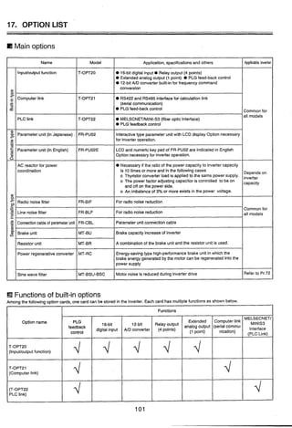
Downloaded 31 times
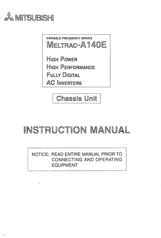

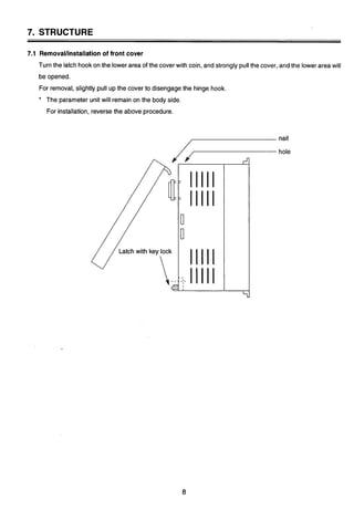
![7.2 PARAMETER UNIT
Installation of the Parameter Unit
The PU may either be installeddirectlyto the inverteror connectedto the inverter bythe optional cable so that
it may be hand-heldor installedto a panel. The PU may be installed and remove when the inverter is powered
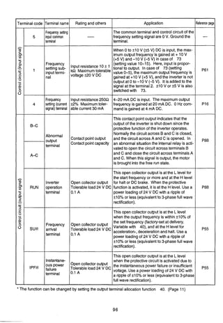
up or running.
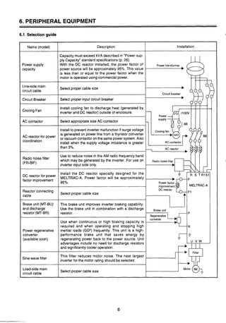
(1) Direct Installationto the Inverter
The PU is used on the front cover of the inverter(electricallycoupled by the connector). Forthe model not
equipped with the PU, removethe accessory cover from the inverter front cover and install the PU to that
position.
(1) Installation
1) Fit the fixing hole at the PU bottom into the catch of
the inverterfront cover.
2) Gently push the PU into the installationspace in
the inverter. The PU is fixed into the inverter by the
spring action of the top button of the PU.
- (2) Removal
1) Gently finger-pushthe top button of the PU.
(Arrow @)
2) Pull the PU toward you using the catch as a
support.
Fixinghole Catch
[CAUTION] The PU should only be installedon the inverter when the invertercover is installed.
(2) Connection Using the Cable
The PU may be installednot only to the inverterbut also on the surface of a panelor may be hand-heldfor
adjustment, maintenance, inspection, etc. In this case, the dedicated cable (option) is required for con-
nection of the PU and inverter.
(1) Connection
Securely insert one end of the cable into the inverter
connector and the other end into the PU as shown on
the left. Insertthe cable plugs along the connector
guides (as shown on the left).
(The inverter may be damaged if the plug is inserted in
the wrong direction.)
(2) Fixture
Secure the inverter-sidecable plug with installation
screws as shown on the left.
Fix the PU-sidecable plug so that the cable may not be
@.:@ Insertalong the guides.
disconnectedby its own weight.
/-
[CAUTION] The dedicated PU cable (option) may only be used to connect betweenthe PU and inverter.](https://image.slidesharecdn.com/fr-a140e-140613032109-phpapp02/85/Fr-a140-e-13-320.jpg)
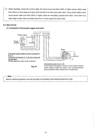
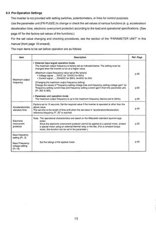
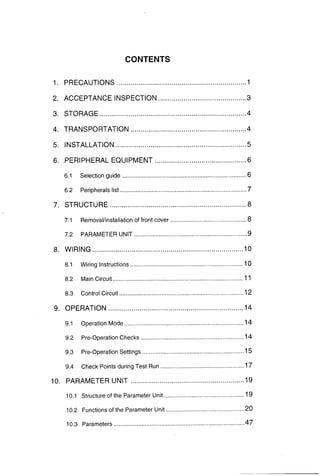
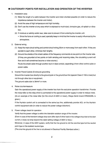
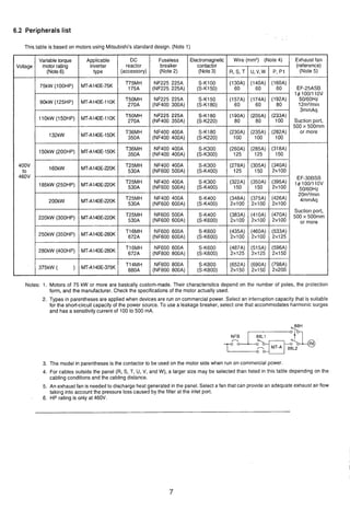
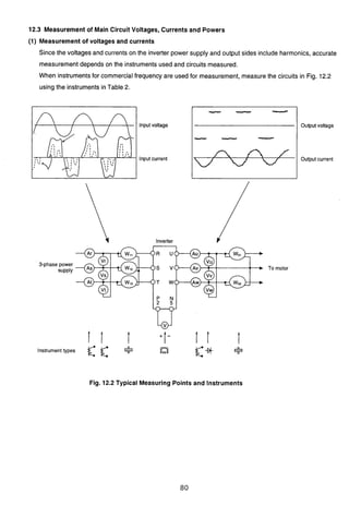
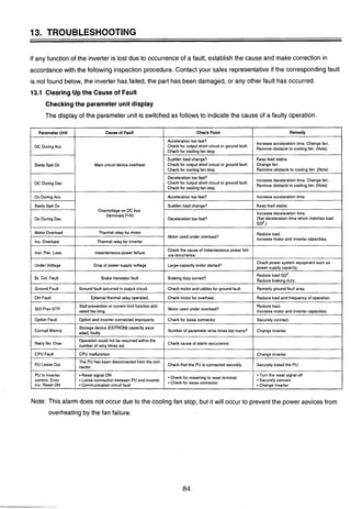
![9.4 Check Points during Test Run
After checking.thatthe inverterstart signal is off (inthe external signaloperation mode), switch on the no-fuse
breaker (NFB) and magnetic contactor (MC) in the inverter input circuit.
Perform a test run and check the operating status in the following procedure:
Power on ........................................The inverter LED (4 digits) is lit
+For operation using
externalsignals
I
4
For operation using For full information on
the parameter unit -operation, see the section of
I the "PARAMETER UNIT"
1 1 (from page 19 on ).
When the power is switched on, the
Operation
inverter equipped with the parameter unit
I mode 1is automaticallyset to the external signal
o~erationmode and also to the
Tum on the forward or reverse rotation
start signal (switch).,,
I 2.setting
press the (PU key to select the
parameter unit operation mode.
Start
Press the [FWD]or [REV] key.
(At this time, the monitoring mode is
selectedautomatically.)
donitoring mode.
Acceleration
Slowly turn the frequency setting
counterclockwiseto the
fully counterclockwise(zero) position. Press the [STOP] key.
Turn off the forward or reverse rotation
start signal (switch).
'Note: If the parameter unit is not in the monitoringmode, a frequency increase or decrease is not
displayed
Direct setting
Enter the requiredfrequency with
numeral keys and press the [WRITE]
....The motor speed increases in
proportionto the rise in
frequency meter reading"
(frequencyvalue indicated on
the parameter unit).
U
Slowly turn the frequency setting
potentiometerclockwisefrom zero to the
fully clockwise position.
....The motor speed decreases
in proportion to the fall in
frequency meter reading
(frequencyvalue indicated on
the parameter unit). When
the output frequency reaches
the DC dynamic brake
operation frequency, the DC
dynamic brake is applied to
bring the motor to a sudden
stop.
press the [i]key until the required
frequency is reached and press the
key.
Il](https://image.slidesharecdn.com/fr-a140e-140613032109-phpapp02/85/Fr-a140-e-21-320.jpg)
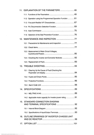
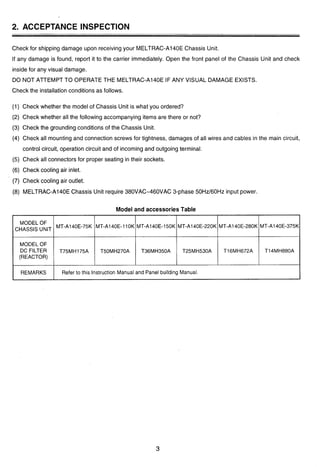
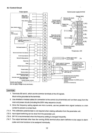
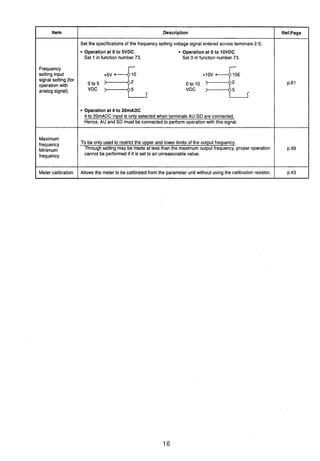
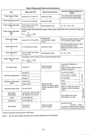
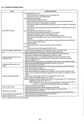
![10.2 Functionsof the Parameter Unit
The PUmay be used ina wide variety of applicationsrangingfrom motoroperationto monitoringas described
below:
Note: A parameterwill be referredto as Pr.
Selectingthe operation mode
External operation andlor PU operation mode can be selected.
Externaloperation ......The inverteris operated using the start switch and
frequency setting potentiometer connectedto the inverter
terminal block.
PU operation ..............The inverter is started/stopped and runningfrequency is
set from the PU keys.
PU/externalcombinedoperation
..............The inverter is operated usingthe PU and externalswitch
and potentiometer.
The combined operation may be performed in either of the following methods:
1) The PU keys are usedfor start and stop, and the external potentiometer is
usedfor frequency setting.
2) The externalswitches are usedfor start and stop, and the PU keys used
for frequency setting.
......The requiredfunction can be readdirectly or rewritten p.30
Convenientfunctions
Operatingthe motor
......
I All set value clear (initialization) p.36
Changing the function set Rewritedisable ...............................p.62
The frequency may either be entered directly from the ten-key pad or by holding
down the [A] (or [V])key.
Frequencymeter calibration ...........p.43
Reset selection ............................... p.61
Monitoring
The operating status (e. g. output frequency, motor current, input power) can be
checked, and I10terminal states and up to eight past alarm definitionscan be
monitored. The inverteris monitored by either the inverter LED display, PU main
display or PU level display.](https://image.slidesharecdn.com/fr-a140e-140613032109-phpapp02/85/Fr-a140-e-24-320.jpg)
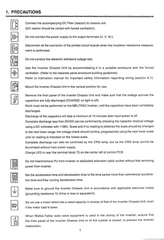
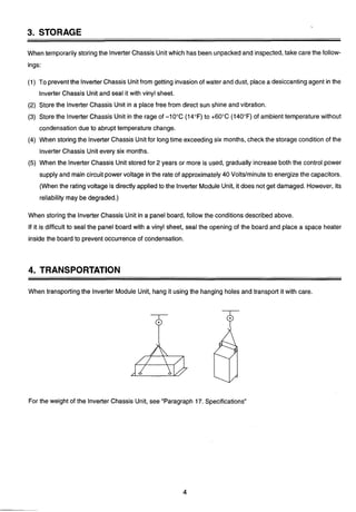
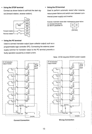
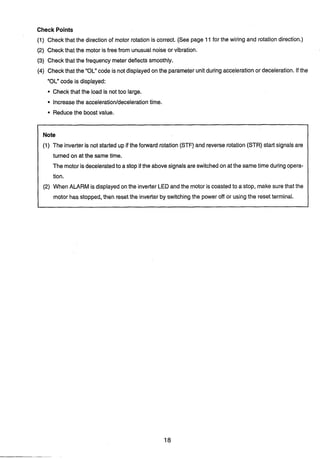
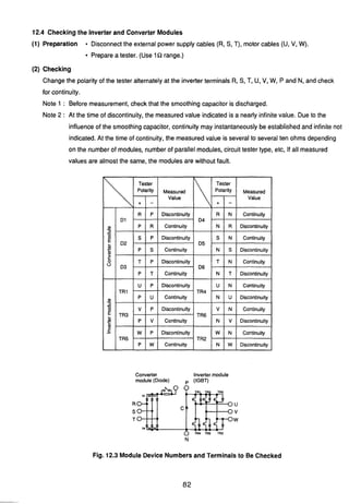
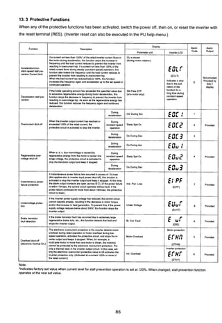
![10.2.1 Operation Mode
The inverterhasfour operationmodes;operationby external input signals, operation by PU, Putexternal input
signal combined operation and programmed operation. The operation mode can be selected (switched) be-
tween the external input signal operation mode and PU operation mode by the mode select keys of the PU.
The other modes are selected by setting in Pr. 79. Pr. 79 also allows the operation mode to be limited (fixed).
The PU operation mode may be output as a signal (see Pr. 40).
Factory-SetOperation Mode
When the input power is switched on (or reset is made), the operation mode is set to the external input signal
operation mode. Hence, poweringthe inverter up makes it ready to operate with external input signals. In this
state, turn on the start signal (across STFJSTR-SD)to start operation.
Limiting(Fixing) the Operation Mode
The operation mode at power on may be limited, e.g. operation from the PU is enabled at power on without
switching the operation mode with the PU's mode select key. For full information on setting the operation
mode, see page 69.
Selectingthe Operation Mode in the Factory-SetState (Pr. 79 setting is 0)
Press the [PU OP] key.
NFB
34input -+aFornard
rotation
Start Reverse
switch rotallon
* Frequency
setting
potentiometer
Inverter Motor
The invertor is inoperative if the frequency setting
potentiometer (setting signal) is not connected (input).
NFB Inverter Motor
34 input -9 MT-A
[CAUTION]
Switching between the PU operation and external signal operation must be performed after the forward (or
reverse) rotation signal of the PU or external input signal has been turned off.
This switching cannot be performed if this signal is on.](https://image.slidesharecdn.com/fr-a140e-140613032109-phpapp02/85/Fr-a140-e-25-320.jpg)
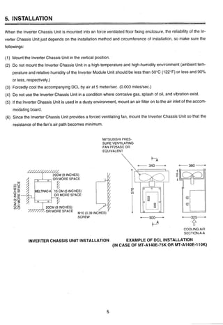
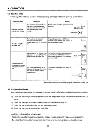
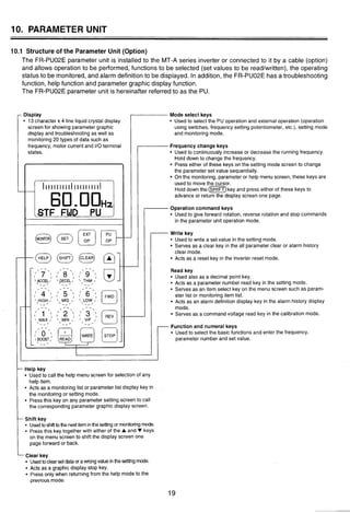
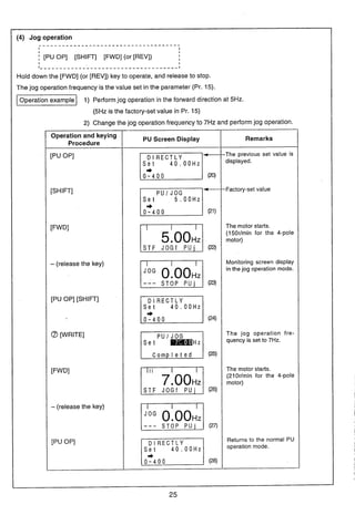
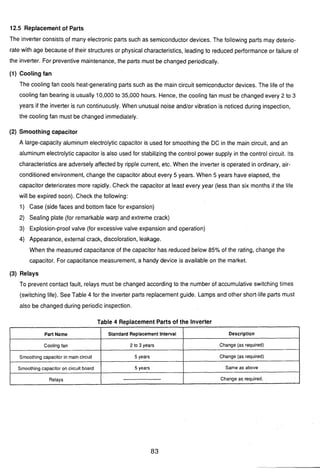
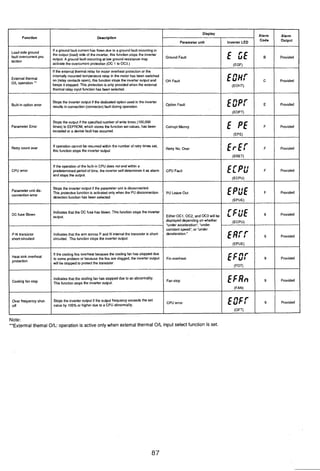
![10.2.2 Operation
The motor can be started and stoppedfrom the PUwithout using the external frequency setting potentiometeror
start switch.
The PU also allowsjog operation.
3
Operating Procedure
(1) Directly entering (setting) the required frequency (Direct setting)
. . . . . . . . . . . . . . . . . . . . . . . . . . . . . . . . . . . . . . . . . . .
I I '
j [PU OP] [Requiredfrequency value] WRITE] [FWD] (or [REV]) [STOP:
I
I
I
I
I
I _ _ _ _ _ _ _ _ _ _ _ _ _ _ _ _ _ _ _ _ _ _ _ _ _ _ _ _ _ _ _ _ _ _ _ _ _ _ _ _ _ _ _ _ _ _ _ _ _ _ _ _ _ _ _ _ _ _ _ _ _ _ _ _ I
Setting the runningfrequency ...........Repeatingthis procedureduring operation
allows the speed to be varied.
Setting example To run the motor in the forward direction at 30Hz.
Note: The parameters, etc. are as factory-set.
Operation and keying
Procedure
Power on
[PU OP]
@a
[WRITE]
[FWD]
[STOP]
PU Screen Display
STOP E X T (1)
D l RECTLY
0 . OOHz
0 - 4 0 0
0 . OOHz
(3)
IIIIIIIII
S T F FWD PU (5)
S T O P PU (6)
Remarks
Displays the latest (previ-
ous) set value.
(OHzinthefactorysetstate)
The motor starts.
(900rlmin for t'.: 4-pole
motor)
The motor stops.](https://image.slidesharecdn.com/fr-a140e-140613032109-phpapp02/85/Fr-a140-e-26-320.jpg)
![(2) Directlyentering (setting)the required frequency (Direct setting)
IL _ _ _ _ _ _ _ _ _ _ _ _ _ _ _ _ _ _ _ _ _ - - _ - - _ _ - - _ _ _ _ - _ _ _ - - _ _ _ _ - _ _ _ - _ _ - _ _ _ - _ _ - _ _ _ - ~
I
I
I
I [PU OP] [Requiredfrequency value] [WRITE] [FWD] (or [REV]) ;STOP:
I
I
I
I
I
l _ _ _ _ _ _ _ _ _ _ _ _ _ _ _ _ _ _ _ _ _ _ _ _ _ _ _ _ _ _ _ - _ _ _ _ _ _ _ _ _ _ _ _ _ _ _ _ _ _ _ _ _ _ _ _ _ _ _ _ _ _ _ - I
SeRing the running frequency ...........Repeating this procedure during operation
allows the speed to be varied.
-1 After running the motor at 30Hz again as set on the preceding page,
change the set value to 60Hz
Operiation and keying
I PU Screen Display I Remarks
I Procedure I
I I---
S T O P PU 1 (7) 1
I I I I I I I I I
S T F FWD PU
The motor runs at the pre-
ceding set value.
D l R E C T L Y
0 - 4 0 0
PIS T O P PU](https://image.slidesharecdn.com/fr-a140e-140613032109-phpapp02/85/Fr-a140-e-27-320.jpg)
![(3) Setting the requiredfrequency by continuous speed change using the [A]or [V]key
(Step setting)
. . . . . . . . . . . . . . . . . . . . . . . . . . . . . . . . . . . . . . . . . . . . . . . . . . . . . . .1 I
I I
; [PUOP] [A](or[V]) WRITE] [FWD](or[REV]) CSTOPI II
I I
I - - - - - - - - - - , - - - - - - - - - - - - - - - - - - - - - - - - - - - - - - - - - - - - - - - - - - - l
-1 Change the preceding setting (60Hz) to 40Hz and run the motor inthe
forward direction.
Note 1: Holdingdownthe [A]or [V]keygraduallyincreasesthe rateof changeof the set frequency.
Set to the target value by pressingand releasingthe key as required.
Note 2: When the frequency has been set to the requiredvalue, the WRITE] key mustbe pressed
to store the set frequency.
(Whenthe powerisswitchedoff or when the PUoperation modeisswitchedto the external
operationmodeandthenswitchedback,thefrequency returnstothesetvalueasithadbeen
before the change (60Hz in this example).)
Remarks
The previous set value is
displayed
This value changes (re-
duces) continuously while
('"he mkey is pressed.
The motor starts.
(1200rlmin for the 4-pole
motor)
The motor stops.
The set value isstoredinto
the invertermemory.
(Validanytimeafterthe[A]
or [V]key is pressed.)
Operationand keying
Procedure
[PU OP]
[
INote':
[FWD1
[STOP]
[WRITEINQe2:
PU Screen Display
D l R E C T L Y
Set 60.OOHz,
+
0 - 4 0 0 (14)
D l R E C T L Y
Set 60.OOHz,
+ 5 9 . 9 9 H z
0-400
D l R E C T L Y
40.00Hz
0-400
STOP P U (18)
(19)](https://image.slidesharecdn.com/fr-a140e-140613032109-phpapp02/85/Fr-a140-e-28-320.jpg)
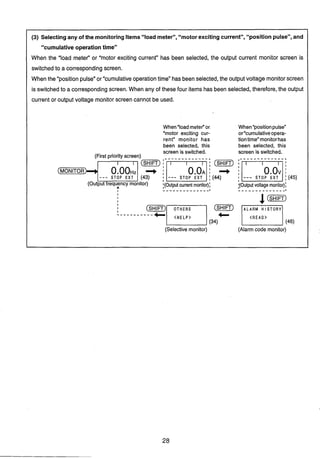
![10.2.3 Changing the Monitor Screen
The invertercan be monitoredby either the LED (red light emitting diode) display on the inverter,the 5-digit liquid
crystal display on the PU (PU main monitor) or the PU level meter. These displays are selected by the following
method: 3
1. Inverter LED display
Setting Pr. 51 on the PU allows selection from 16types of data.
For full informationon the setting method, see the explanation of Pr. 51.
Pr. 51 is factory-setto the output frequency display (Pr. 51 =I).
2, PU level meter
Setting Pr. 53 on the PU allows selection from 15types of data.
For full informationon the setting method, see the explanation of Pr. 53.
Pr. 53 is factory-set to the output frequency display (Pr. 53 =I).
3. PU main monitor
5 types of data can be selected in sequence by the SHIFT key as shown below.
Among the five monitor screens, the fifth monitorscreen (selective monitoring)allows selectionfrom 12types
of data such as the frequency set value and runningspeed.
f
Additionally, Pr.52allowsselectionfromfour typesof datasuchasthe loadmeterandcumulativeoperationtime.
For full informationon the select items, see the explanation of Pr. 52.
1 (1) Monitor selection in the factory-set state
Example
I _ - _ _ - _ _ _ _ - - - - _ _ _ _ - - - - - - - - - - - - - - - - - - - - -
I
I
I
(~irstpriot!ity screen) (Firstpriontyt screen)
S T O P E X T (30)
(Outputvoltage monitor)
4
I
I
I
I (SHIFT) I O T H E R S I @&@ ALARM HISTORY]
2 U V T 6
By pressingthe [m]key,five types of data can becalled in sequence. Pressthe [WRITE] key
on any monitor screento always start from that screen (first priorityscreen). Example: By pressing
the [WRITE] key on the output voltage monitor screen, pressingthe C f i 0 m ) keyfirst callsthe
outputvoltage monitorscreen, which isthe first priorityscreen. (The sequenceof screens switched
by the cm) key remains unchangedfrom the above diagram.)](https://image.slidesharecdn.com/fr-a140e-140613032109-phpapp02/85/Fr-a140-e-30-320.jpg)
![1 (2) Selecting a new monitor item in the selective monitoring mode
pT6i-qSTOP PU
3 Voltage
4 Alarm H i s B
El7 Shaft Trg
1 0 Therm OIL
1 1 Peak I
O S T R ORM O S T O
O A U O R H O R E S
. . . . . . . . . . . . . . . . . . . . . . . . . . . . . . . . . . . . . . . . . . . . . . .I
I
* For the items selectable,
C w ) [ v ] [READ] [WRITE] 1 see page 56.
I
I (35)
I
I
I
I
I
I
I Monitor select screen (for the
I
I
I way of calling this screen,
I
I
I refer to the preceding page)
I
I
I I
. - - - - - - - - - - - - - - - - - - - - - - - - - - - - - - - - - - - - - - - - - - - - - - J
-1 Select the input terminal state screen in the selective monitoringmode.
that monitor screen.
Note 2: When the selective monitor screen is not the first priority screen as inthe above operation, the selected data is
erasedfromthe memoryassoonasthe power isshutoff orthe otheroperation mode (suchasexternal operation)
is selected.
In this case, the selective monitoring mode must be selected again by the above procedure.
When the selective monitor screen remains as the first priority screen, the selected data remains intact in the
Remarks
The following operation can also be
carried out in the external operation
mode.
Holddown ( m ) a n d press ['dl or
[A]to advance or return the screen
one page.
By pressing the (m)key, the
other monitor screens can be called.
prioritywhen the other operation mode
Operation and keying Procedure
[PuOP]
(MONITOR)
(SHIFT)(SRiF-7)(SHIFT)(m)
(HELP)
Hold down G ~ T )
[ V l [ V l [s'l
Without pressing ( S ~ T ]Key
[TI181
[READ] [WRI'TE]
Note 1: Inthis state, the 110terminal
I memory.
is switched to the monitoring mode. (Refer to the preceding page.) When first priority has been given to other
data, press the [WRITE] key with that monitor screen being displayed.The first priority screen then switches to
PU Screen Display
(36)
(37)
(38)
(39)
(40)
(41
(42)
states selected here are first displayed with](https://image.slidesharecdn.com/fr-a140e-140613032109-phpapp02/85/Fr-a140-e-31-320.jpg)
 : Likethe main monitor, allows 15types of data to be monitoredin %.
(Differentdata from those in the main monitoringcan be selected.)
Note: For more informationon the 20 monitor screens available, refer to page 59 (monitor/output signal selection).
*
e The following modes are displayed on the parameter unit:
t t fI PU : PU operation
mode.
IIIIIIIIIIIIIIIIIIIII
120.00STF FWD PU
(1) Direct in
Monitoring mode
[Setting ] ]I (3)(2) JogCombinedoperationPU/exter-
nal operation 1
(power on)
(4) Specialoperation
Indicatesthe stall prevention
function is activated.
z:rDisplayunitl
Externaloperation mode
Monitoringmode Setting mode
1 f monitor 9 DC bus voltage (1) Parameter read
2 l monitor 10 Output current peak (2) Parameterwrite
3 V monitor 11 DC bus voltage peak (3) Graphicdisplaymode
(48)
PU operation mode
4 Alarm history 12 Thermal load factor I
Indicatesthe operation
5 Speed 13 Input terminal monitor
6 Regenerativebrake duty 14 Output terminal monitor
7 Input power 15 Frequency command' 1 I. .
8 Output power 16 Output torque 1
I$- $- +Help mode (see page 34)
(1) Monitoring (4) Parameter clear (8) Troubleshooting
(2) PU operation 1) 0to 899 clear (exceptcalibrationfunctions) 1) Motor does not rotate.
(3) Parameter 2) All clear (including calibrationfunctions) 2) Speed does not increase.
1) Setting (5) Alarm history 3) Acceleration/deceleration time is long.
2) Parameter list (6) Alarm history clear 4) Output current is large.
3) Change list (7) Inverter reset
4) Initialvalue list](https://image.slidesharecdn.com/fr-a140e-140613032109-phpapp02/85/Fr-a140-e-33-320.jpg)
![Set P r . N O .
FOR P R . L i s t
pqS T O P E X T
10.2.4 Changing or Checkingthe Function (Parameter) Set Values
By changingthe parametersof the inverter,the functionand performanceof the inverterand motorcan be matched
to the application.The factory-setvalues need not be changedwhen they are appropriate.The parameter numbers
are represented Pr.
Operating Procedures
(1) Directly entering the Pr. number, calling and setting the parameter
-----------------_-----------------------------
[PU OP] [SET] @ a[READ] a@ @[WRITE]
Pr.number
*The function names (abbreviation) of parameters Pr. 0 to Pr. 9, which are most often used, are given below
the numerals on the numeral keys (0 to 9).
Isetting exampleI Setting Pr. 7 (accelerationtime) to 3.5 seconds.
Operation and Keying Procedure
[PU OP] [SET]
a
[READl
*
@ [READ] [WRITE]
(m)
or (WT]
PU Screen Display
(49)
(50)
Remarks
Currentset To callthe parameterfunction graphi-
value
seltins tally
range
(HELP)
(ern)
4- (55)
(Returns to the previous screen)
(52)
(53)
(54)
Press the (-R] key to move
to the CM-R) screen.
After the setting is complete, press
the key to move to the next
parameter.](https://image.slidesharecdn.com/fr-a140e-140613032109-phpapp02/85/Fr-a140-e-34-320.jpg)
![(2) Calling the parameter list and setting the parameter
C - - - _ - - - - - - - - - - - - - - - - - - - - - - - - - - - - - - - - - - - - - - - - - - - - - - - - - - - - -
[PU OP] [SET] (KP][ ] [READ] aa@[WRITE]
I
'--------------------------------- - - - - - - - J
Set valuew
Isetting example1 Setting Pr. 13 (startingfrequency) to 1Hz.
Operation and Keying Procedure
[PU OP] [SET] [READ]
(HELP)
Note
I - - - - - - - - - - - - - - - - -
(rn)[V] [V] [V];1- - - - - - - - - - - - - - - - - !
[READ]
@ [WRITE]
(-1
or (m)
Note: Hold down the (SHIFT) key and press the [V] key.
PU Screen Display
SETTING MODE
S e t Pr.NO.
FOR P R . L i s t
< H E L P >
Remarks
13 S t a r t F To callthe parameterfunction graphi-
0 . 5 0 H z cally
(CLEAR)
(63)
(Returns to the previous screen)
14 L o a d V F
(62)
After the setting is complete, press
the (SHIFT)key to move to the next
parameter.](https://image.slidesharecdn.com/fr-a140e-140613032109-phpapp02/85/Fr-a140-e-35-320.jpg)
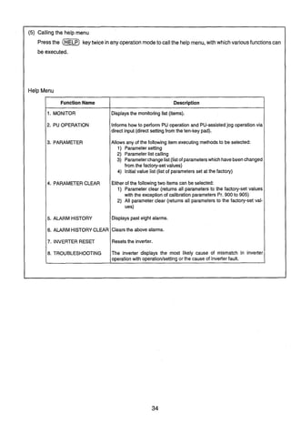
![10.2.5. Applying the Help Function
By pressing HELP in any PU operation mode, the inverter gives the operation guide.
.................................................................
I I
j (1) [~onitoringmodel (m)-t onitorin^ (item) list1
I
I
j (2) ((HELP) + Iparameter (item) list1
I
I
I
I I
I I
I (before Pr. number setting) I
j (3) lSeningmodel (w)+ [Graphic display]
I
I
I
1 I
I I
I (after Pr. number setting) I
j (4) PU operation model (HELP) + 1~ e yoperation explanationI
I
j (5)
Operatingand Keying Procedure
(WP](-R]
(HELP)
I
I
I .
General operation mode] (m)(-1 + I el^ (item) list] I
I I
I - - - - - - - - - - - - - - - - - - - - - - - - - - - - - - - - - - - - - - - - - - - - - - - - - - - - - - - - - - - - - - - - l
(1) Help function in the monitoring mode
* Move the cursor (indicated by +) using the [A] (or [V]) key, then press the [READ] Key to select the
corresponding monitor item.
* Furthermore,pressthe [WRITE]keytostorethe datasothat this screenisdisplayedfirst inthe monitoring
mode after the monitor screen has been switchedto another display screen.
PU Screen Display
ST 0 P PU (64)
Remarks
This operation may be performedon
any monitor screen.
Alsothisoperationmaybeperformed
during inverter operation.](https://image.slidesharecdn.com/fr-a140e-140613032109-phpapp02/85/Fr-a140-e-36-320.jpg)
![(2) Help function in the setting mode (Part 1)
Move the cursor (+) and press the [READ] key to select any parameter.
(3) Helpfunction inthe setting mode (Part2) Operation example Pr. 0(torqueboost)
Operating and Keying Procedure
(PUOP)(SEZ)
(HELP)
-Sr On this screen, pressthe SHIFT key to graphically display the parameter of the next number.
(4) Help function in the PU operation mode (beforefrequency setting)
PU Screen Display
Set P r . N O .
FOR P r . L i s t
2 M i n . F I
Operating and Keying Procedure
( i m p )
0 -
(HELP)
Remarks
PU Screen Display
Set P r . N O .
FOR P r . L i s t
0 T r q . B s t 1
6 . 0 %
F + (70)
Remarks
The function of the corresponding
parameter is displayed graphically.
Remarks
b y operation exp~anationscreen
a To set the frequency (f), use the
0 to 9 numeral keys.
a Then press the pRITE] key.
a Furthermorepress the [FWD]or
[REV] key to start.
Operating and Keying Procedure
(P-)
PU Screen Display
Dl R E C T L Y
0 - 4 0 0I..--.1(71)
Fse t : 0 - 9
Then:WRITE](https://image.slidesharecdn.com/fr-a140e-140613032109-phpapp02/85/Fr-a140-e-37-320.jpg)
![Operating and Keying Procedure
- -- - - - - --
Operations in the help menu not previouslydescribedwill now be described.
(5) -1) Parameterchange list
Displays only the set values of the parameterswhich have been changed from the factory-set values.
PU Screen Display
1 SettingMODE
2 P r . L i s t
3 + S e t P r . L i s t
Remarks
Help menu screen
Help menu screen regarding the pa-
rameters
Onlytheparameterswhichhavebeen
changed in setting are displayed on
part of the screen.
(The screen shown on the left indi-
cates an example of Pr. 0 whose
value has been changedto 8%.)
(5) -2) Initialvalue list
Displaysalistofthefactory-set valuesof the parameters.Thisfunction isconvenientwhenatypical setvalue
is lost.
Operating and Keying Procedure
[READ]
PU Screen Display
3 S e t - P r . L i s t
Remarks
Entersthesettingmodeof theparam-
eter at the cursor position.](https://image.slidesharecdn.com/fr-a140e-140613032109-phpapp02/85/Fr-a140-e-39-320.jpg)
![(5) -3) Parameterclear and all parameter clear
Parameterclear andall parameterclear differasfollows:The parameterclearoperationdoes notclearthe
calibration parametersof Pr. 900 to Pr. 905, but the all parameterclear operationclears all parameters.
Clear indicates that the parametersare set to the factory-setvalues.
Operating and Keying Procedure
( O F
PU Screen Display Remarks
Pressthe [PU OP], [CLEAR] or other
key to returnto another mode.
Pressthe [PU OP], [CLEAR] or other
key to returnto another mode.
3 C l e a r None
Exec<WRITE>
Cancel<CLEAR>
[WRITE]
[Vl [READ1
[WRITE]
*
C l e a r P r .
(83)
C L E A R ALL P r .
Exec<WRITE>
Cancel<CLEAR>
/(84)
C L E A R ALL P r .
(85)](https://image.slidesharecdn.com/fr-a140e-140613032109-phpapp02/85/Fr-a140-e-40-320.jpg)
![(5) -4) Alarm history and alarm history clear
* The alarm history can also be displayed by pressing the SHIFT key in the monitoring mode.
(See page 26)
(5) -5) Inverter reset
If any protectivefunction of the inverter hastrippedthe inverter,the following operation allows the inverter
to be reset via the keypad.
The inverter can also be reset by switchingthe power off or connecting the terminals RES-SD.
Remarks
Alarm history screen
Pressthe [PU OP], or [SHIm key to
return to another mode.
Operating and Keying Procedure
(WP)
PU Screen Display
Operating and Keying Procedure
(OP)
Hold down [ S H l m and press [V]
furlher [V] [V][READ]
[WRITE]
Holddown (am)and press [V]
6 A l a r m c l e a r
7 I n v . R e s e t
(88;
1 U V T 5
2 U V T 6
FI[READ1
Exec<WRITE>
Cancel<CLEAR>
[WRITE]
PU Screen Display
I N V . R E S E T
Exec<WRITE>
Cancel<CLEAR>
Remarks
When anothermonitoritemhas been
selected onthe monitoringfirst-prior-
ity screen, that monitor screen is dis-](https://image.slidesharecdn.com/fr-a140e-140613032109-phpapp02/85/Fr-a140-e-41-320.jpg)
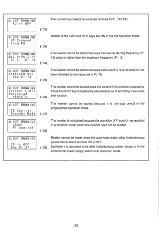
![10.2.6 Troubleshooting
Selectthis modewhen the inverteroperationappearsfaulty. The most likelycause of the fault is displayed.
Thisoperation modecanbeselectedduringthe inverteroperation (PUoperation,externaloperation), alarm
trip (protection activated), etc.
The fault on each display screen are described below.
M. NOT RUNNING (Motor does not rotate)
M . N O T RUNNING
The inverter has alarm-tripped (protection activated), resulting in output
A L A R M shut-off. Pressthe [SHIFT] keyto displaythe cause of protectionactivated.
I n d i c a t e d
< S H I FT>
The maincircuit powerof the inverter is lost, or open phase has occurred in
NO I I P Power the power supply. Checkthe power supply.
o r Phase L o s s
M.NOT RUNNING Both start signals STF and STR are ON or OFF.
STF, S T R
b o t h a r e OFF
I I I (99)
M . N O T R U N N I N G The output shut-off input terminal MRS is ON.
MRS i s ON
1(100)
M . N O T R U N N I N G The inverterstarting frequency (Pr. 13) set value is higher than the current
S e t F < S t a r t F
P r . 1 3
1set frequency.
(101)
Operating and Keying Procedure
=(HELP)
Holddown (SHIFT)and press [V]
further [V][V][V]
(READ)
PU Screen Display
3 P r . L i s t
6 A l a r m c l e a r
7 I n v . R e s e t
2 M.Spd E r r o r
3 M . A I D e c E r r
Remarks
Symptom menu.
Movethecursortothe itemmatching
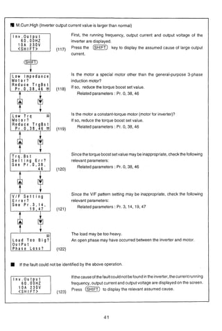
the fault andpressthe (READ) key.](https://image.slidesharecdn.com/fr-a140e-140613032109-phpapp02/85/Fr-a140-e-42-320.jpg)
![M.SPEED ERROR (Speed does not match the runningfrequency set value)
Since the running frequency set value is higher than the maximum
SetF>MaxFlIF2 frequency(Pr. 1)setvalue, the runningfrequencyremainsatthe maximum
6 0 . 0 0 Pr1118
(110) frequency.
Sincethe runningfrequencysetvalue islowerthanthe minimumfrequency
S e t F < M i n . F l
6 0 . 0 0 P r . 2
(Pr. 2) set value, the running frequency has been risen to the minimum
(111) frequency.
Sincethe runningfrequency set value iswithin the frequencyjump setting
Fjump W o r k i n g range, the runningfrequency has jumped.
S e e P r . 3 1 + 3 6
The current limit function has been activated and forced the running
C u r r e n t L i m i t
A c t i v a t e d
frequencyto reduce. Pressthe SHIFTkeytodisplaythecauseof activating
(113) the current limit function.
The operation of PI control has causedthe runningfrequency to be offset
Under from the set value.
PI C o n t r o l
(114)
M.A/Dec Err
(Acceleration/decelerationtime is longer than the value set in Pr.7lPr.8)
Accelerationtime set value (Pr.7) is displayed.
Frequencyreachedinthe above set time (acceleration/decelerationrefer-
ence frequency, Pr.20) is displayed.
S e t 5 . 0 s
0+ 60.00HZ
S e t 5 . 0 s
60.00HZ+O ,
Decelerationtime set value (Pr.8) is displayed.
Frequencyfrom which deceleration is made inthe above set time (accel-
(115) erationldeceleration reference frequency, Pr.20) is displayed.
A
[A] [v]
Assumedcauseof longeraccelerationldecelerationtimethanthe setvalue
is displayed.
'I Stall preventionfunction (current limit function) is implemented.
Set time is too short.
Set Too L o w ?
Motor load is heavy.
(116) Pr. 22(stall preventionoperation level) setting error.](https://image.slidesharecdn.com/fr-a140e-140613032109-phpapp02/85/Fr-a140-e-44-320.jpg)
![10. 2.8 Calibratingthe Frequency Meter
The PU allowsthe calibration (adjustment)of a meterconnectedacross the meterconnectionterminal FM-SD
or AM-5 of the inverter.
When a digitalmeteris used, the PUallowsthe frequency of the pulsetrain output signalto be adjusted (across
terminals FM-SD).
(1) Calibration of the FM-SD output
Preparation ('I) Connect a meter across inverter terminals FM-SD. (Note polarity. FM is the positive
terminal.)
(2) When acalibrationresistorhasalreadybeenconnected,adjustthe resistancevaluetozero
or removethe resistor.
(3) When 1or2 hasbeenset in Pr.54to selectthe runningfrequency or inverteroutputcurrent
astheoutputsignal, presetinPr. 55or Pr.56 the runningfrequency orcurrentvalueatwhich
the output signal is 1440Hz.This 1440Hz normally makes the meter full-scale.
* The motor need not be connected.
Operating Procedure (The following example indicatesthat the meter is calibratedto the runningfrequency
of 60Hz.)
Operating and Keying Procedure
( i ~ )(SET)
o ( R E A D )
Set the running frequency.
@I (WE]
(FWD)
Adjustthefrequencymeterreadingto
a predetermined position using the
[A]or [V]key.
PU Screen Display
900 FM Tune -Lzzil
900 FM Tune
Run I n v e r t e r
M n t r F 60.00Hz
M n t r F 60.00Hz
Completed
<MON I T O R >
IIIIIIIII I I I I I I I I I
WI
Remarks
-- -
-The current PU set frequency is dis-
played.
Forward operation is performed at
60Hz.
Thefrequency meter reading moves.
Calibration is complete.
Note: This calibration (Pr. 900) is only valid when any of 1 to 3, 5 to 14, 17, 18 and 21 has been set in Pr. 54 to output
a signalto terminal FM. When any othervalue hasbeenset (signaloutput to terminalAM has beenselectedin Pr.
54),the absenceof Pr.900isdisplayedonthe screenas soonasthis parameterisselectedbythe aboveoperation.](https://image.slidesharecdn.com/fr-a140e-140613032109-phpapp02/85/Fr-a140-e-47-320.jpg)
![Operating and Keying Procedure
-(SET)
S 0 0 Cm)
Set the running frequency.
@ 0 (m)
0
Adjustthefrequencymeterreadingto
a predetermined position using the
[A]or [V]key.
(m)
(MONITOR)
(2) Calibration of the AM-5 output
preparation (1) Connect a meter of 0-1OVDC acrossinverterterminalsAM-5. (Notethe polarity. AM is the
positive terminal.)
(2) When 101or 102has beenset in Pr. 54 to select the runningfrequency or inverteroutput
currentasthe outputsignal, presetinPr. 55or Pr.56the runningfrequencyorcurrentvalue
at which the output signal is 10V.
Operating Procedure (The following example indicatesthat the meter is calibratedto the runningfrequency
of 60Hz.)
Note: This calibration (Pr. 901) is only valid when any of 101to 103, 105 to 114,
PU Screen Display
R u n I n v e r t e r
S e t + 0.OOHz
(130)
9 0 1 AM Tune
R u n I n v e r t e r
(131)
M n t r F 60.00Hz
M n t r F 60.00Hz
Completed
<MON I TOR>
(134)
117, 118 and 121 has been set in Pr.
Remarks
The current PU set frequency is dis-
played.
Forward operation is performed at
60Hz.
Thefrequencymeter readingmoves.
Calibration is complete.
54 to output a signal to terminalAM. When any other value has beenset (signal output to terminal FM has been
selectedin Pr. 54), the absenceof Pr. 901 is displayedon thescreen as soon as this parameter isselectedbythe
above operation.](https://image.slidesharecdn.com/fr-a140e-140613032109-phpapp02/85/Fr-a140-e-48-320.jpg)
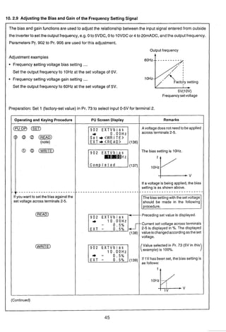
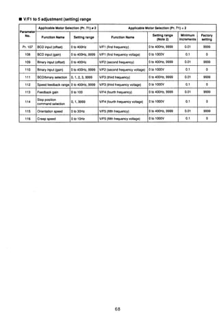
![Note: Pr. 904, Pr. 905 (bias and gain of frequency setting current signal) can also be set in a similar manner.
Pr. 903 and Pr. 905 (gains) remain unchanged if Pr. 20 (acc./dec. referencef) is changed.
-
Remarks
--0.0% may not be displayed,
The bias setting is as follows:
v
Operatingand Keying Procedure
(m)
PU Screen Display
9 0 2 E X T V b i a s
1 0 . 0 0 H z
(139)
A voltagedoes not needto beapplied
acrossterminals2-5, andgain setting
is made with 5V (or 10V) in the in-
9 0 3 EXTV a i n
v
set voltage across terminals 2-5. shouldbe madeinthe following pro-
(READ)
(rn]
(m)
9 0 3 E X T V g a i n -Factory set value
6 0 . 0 0 H z (Preceding set value is displayed.)
9 7 . 1OIo
19 9 . 0 % Current set voltage across terminals
(141) 2-5 is displayed in %. The displayed
valueischangedaccordingasthe set
9 0 3 E X T V g a i n
6 0 . 0 0 H z
voltage.
9 7 . 1 %
9 9 . 0 % Value selected in Pr. 73 (5V in this
example) is 100%
6 0 . 0 0 H z
9 9 . 6 %
(142)
Set voltage across terminals 2-5.
100.0% may not be displayed.](https://image.slidesharecdn.com/fr-a140e-140613032109-phpapp02/85/Fr-a140-e-50-320.jpg)
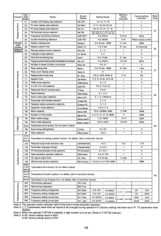
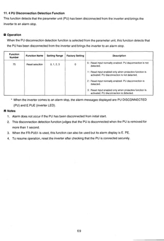
![11. EXPLANATION OF THE PARAMETERS
11.1 Functions of the Parameters
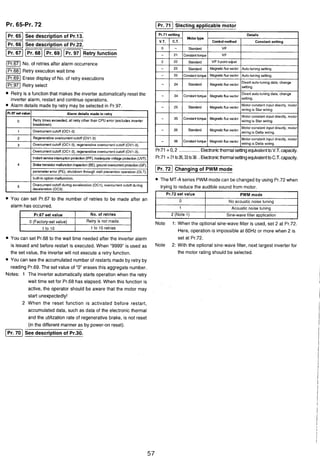
Pr. 0-Pr. 8 Note: Parameter is abbreviated as Pr. Setting multi-speed settings
1st Multi-speedsetting (high) 1- 4th Multi-speedsetting
IPr2nd Multi-weedsetting (medium) 5th Multi-speedsetting
Setting torque boost (manual)
Voltage at 0 Hz can be adjusted (biased) as necessary to
provide additional starting torque at low frequencies.
- - .
3rd Multi-speedsetting (low) 6th Multi-speedsetting
7th Multi-speedsetting
Input terminals RH, RM, and RL alone or in combination are
used to select each speed.
Each preset speed can be set to any value between 0-400
Hz during operation of the inverter. The speed can also be
set by using the "[A] [V]"keys.
Up to 10 speeds can be set by combining these parameters
with JOG frequency (Pr. 15), upper limit frequency (Pr. I), or
lower limit frequency (Pr. 2).
A Speed 1Note 1: 1% of factory-setting (manual torque boost).
Note 2: When Pr. 80 and Pr. 81 have been set to select Primary
Magnetic Flux Control mode, there is no need to set this
parameter
I-
Setting Maximumand Minimum frequency limit
(Pr Maximum frequency limit Minimum frequency limit
Maximum and minimum frequency output limit can be clamped.
Betweer
Between
Belwee~
l and SC
i and SC
and SC
I.When Pr. 24-Pr. 27 are set to 9999 (factory-set value), Speeds
4-7 cannot be selected.
2. Multi-speed selections take priority over the main speed
(between terminals 215 or 415).
3. Multi-speeds can also be set during PU operation and external
operation.
Note: To set a frequency of 60Hz or more, use Pr. 18.
lPr.1p g
Settina accelerationldecelerationtime4Setting base frequency
Acceleration time Accelerationldecele~ationbase frequency
Decelerationtime -1 Accelerationldecelerationtime unit
Base frequency ImBase frequency voltage
Check motor nameplate for base frequency and voltage
data. Enter frequency in Pr.3, and voltage in Pr.19. This
will establish the correct volts1Hz ramp. Example: Pr.3 =
60 (Hz), Pr.19 = 460 (volts).
Pr.19 can be set to any motor nameplate voltage provided it
is not higher than the voltage supplied to the inverter.
Example: a typical high speed spindle motor nameplated
330V, at 300Hz; set Pr.3 = 300(Hz) and Pr.19 = 330(volts).
An incorrect setting of either Pr.3 or Pr.19 will apply the
wrong VIHz ramp to the motor resulting in motor heating,
and overvoltage trips on overhauling loads.
Setting 8888 in Pr. 19 results in voltage output equivalent
to 95 percent of power supply voltage.
I
Set Pr. 7 to the time needed to reach the set value for the Pr. 20.
Set Pr. 8 to the time needed to reach the set value for OHz.
For Pr. 21 accelerationldeceleration time unit, the setting
range and the minimum setting unit can be set as follows:
Set value 0: 0-3600 seconds (The minimumsetting unit is 0.1 seconds.)
Set value 1: 0-360 seconds (The minimumsetting unit is 0.01 seconds.)
p y b r a t i 0 4 Time
(Pr71 pJ II I
Note: For a S-shaped accelerat~on/decelerat~onpattern A (see Pr.
I
-
I
29) only, the value must be the time needed to reach the base
Ingeneral, it is importantto set Pr.3 and Pr.19 to rated motor values. frequency (Pr. 3).
When Pr.19 is set to 9999 (factory set value), the maximum output- -(-heoutput wavelength for the wavelength setting signal (analog) is
voltage is as the same as the inverter input supply voltage. set by the gain (Pr. 903 or Pr. 905).
49](https://image.slidesharecdn.com/fr-a140e-140613032109-phpapp02/85/Fr-a140-e-53-320.jpg)
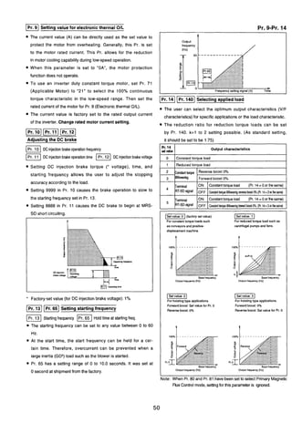
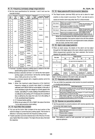
![Pr. 15-Pr. 66
lm15Setting JOG operation
1- JOG frequency JOG acceleration/decelerationtime
For JOG operation, select JOG mode (short between the ter-
minals JOG and SD). JOG operation is started and stopped
by a start signal (input at the STF and STR terminals).
JOG operation can also be performed by using the parame-
ter unit. (Refer to the Instruction Manual.)
I]Selectingexternalthermal OIL relay input
Q The set values 0 and 1 switch the functions of the input
terminal JOGIOH. The JOG function inputs the signal
contact of the JOG operation select signal. When a ther-
mal OIL relay is installed between the motor and the
inverter, or a motor containing a temperature sensor is
used, select the OH function which will allow an input from
the relay or sensor.
The set values 2 and 3 switch the function of the MRS terminal
to the b-contact input specification (normally closed input).
Belween Jo"sD
.w:.:.:.:i:i.:::: .>-. :.:+:.:.:.:.;:.:.:.>>~.:-:,:.:.):.;:.:::, . .........................
~;~~~~:::!:;:~!::~;~:~.:g~~:$:<:.:~;::::~~$,:z:zc,~:;;:.;c~<:<~;c-:.:.:-..;. .........._.................................,,,,,,,,.,..,,...... ...
output transistors I
*
Forward -Reverse >
-1 ((Factory-setvalue) -1
output transistors
(7
I Ishut oll SD b------' I
shut off SD
ml-3
SD
mw output stop
m k
output stop
-
0
IPr. 181 Setting high-speed maximumfrequency limit
Use this parameter for operation at 60Hz or more.
When this parameter is set, the maximum frequency parame-
ter, Pr. 1, is automatically changed to this set value.
Before setting this parameter, confirm that the motor and
machine can withstand high-speed operations.
[-I See description of Pr. 3
1- 201See description of Pr. 7, Pr. 8
[q2211Pr.I661
Setting stall preventionoperation level
(1 Stall preventionoperationlevel(currentlimitingoperationlevel)
IPr.1High speed stall prevention operation level (current
limiting level reduction rate at 400Hz)
IPr. 66 1 Frequency at which stall prevention level reduction begins
Set Pr. 22 for the stall prevention operation level (current
limiting level). Normally, set this parameter to 120% (equal
to the factory-set value).
Setting 9999 in Pr. 22 enables stall prevention operation
level to be set through the signal to the auxiliary input ter-
minal (Terminal 1).
Q To improve the acceleration characteristic of the motor for
high speed operation at 60Hz or more, the current limiting
level in the high frequency band can be reduced. Pr. 66
sets the frequency at which reduction begins, and Pr. 23
sets the reduction rate.
Q When Pr. 23 is set to 9999 (factory-set value), the current
limit of the set value for Pr. 22 remains constant at 400Hz.
1
........-..
IPr661 4 0 0 ~ ~output frequency](https://image.slidesharecdn.com/fr-a140e-140613032109-phpapp02/85/Fr-a140-e-55-320.jpg)
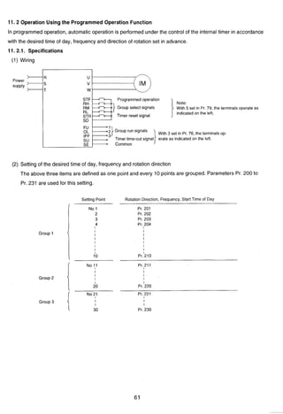
![rPr.24 1Msee descriptionof Pr. 4. Pr. 24-Pr. 36
I-28 Selectinq multi-speedinput compensator- -
A compensator signal input at terminal "1" enables speed
(frequency)compensatorto be made to multi-speedsettings.
[=I Selecting accelerationldeceleration patterns
Set value
0
1
Differentacceleration/decelerationpatternsare provided.
Compensator by auxiliary input
N o t c o m p e n s a t e d (factory-set value)
Can be c o m p e n s a t e d
The selection will dependon the application.
0-1 (linear acceleration/deceleration) is effec-
tive for most applications.
0- (S-shaped acceleration/deceleration A) is
used to accelerate or decelerate to high-speeds. 60Hz or
more, in a short time. This set value selects an
acceleration/deceleration pattern with the turning point of
the S-shaped curve at fb (base frequency). his pattern is
suited for use with machine tools applications.
.[set v a l u e 7 (S-shaped acceleration/deceleration €3) is
used to set constant, S-shaped acceleration or deceleration
at a frequency between f2 (current frequency) and f l
(target frequency). This function can reduce shocks aris-
ing at accelerationor deceleration.
IpiiGq -1 1-1
(linear accalerallow IS-shaped acceleratiow IS-shapedacmleratlow
deceleration) decelerationA) deceleration8)
0 - I
Time
30 Setting regenerativebrake
Externalbrakeresistorselection Maximumregenerativebrakeduty ?
lTo use optional brake unit and brake resistor, set Pr. 30 to 1
/'
and Pr. 70 for %ED. For standard brake unit and brake resis-
tor, %ED is 5% (30 sec/lO min).
lPr. 70 setting must match the allowable brake usage factor of
the transistor in the brake unit.
lWhen Pr. 30 is set to be 0. Pr. 70 is not displayed.
l P r . p z q 3 2 p Z q ~ p z i q
Frequencyjump
lTo avoid resonance during operation due to natural vibration
of mechanical system, the resonant frequency can be
jumped. Three jump points can be set, and the jump fre-
quency can be set above or below each jump point.
lA frequency reference command within the frequency
jump range will result in operation at l A , 2A, or 3A
(below the jump frequency range).
Notes: 1. When the value "9999" is set (factory-set value),
@(Set-"3"ctivates the backlash-reduction function for frequency jump is not executed.
use when the motor is connected to a high backlash load. 2. When Pr. 29 is set to "3",Pr. 33-Pr. 36 are switchedto the
This function temporarily changes the output frequency backlash correction setting function. (Pr. 31 and
at acceleration/deceleration to reduce shocks (or back- Pr. 32 remainvalid as the frequencyjump function.)
lash). Use Pr. 33 to Pr. 36 to set the parameters for backlash 3. The operating frequency within the setting range is
reduction. applied to Jump during acceleration/deceleration.
Range of jump (Operationis avoidedin this range.)
IPr 33
- IPr35] 3A
i ~ 2 B .
" Using Pr. 31 and Pr. 32 ensures that the frequency jump function
will remainvalid.
IPr33) 2A
-
$ IPr321 10
'The operating frequency
commandwithin Jump will
be the operating frequewy
1A in me portionmarkedwith..
>
Frequencysemng signal](https://image.slidesharecdn.com/fr-a140e-140613032109-phpapp02/85/Fr-a140-e-56-320.jpg)
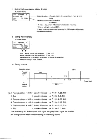
![1Pr. 42 1 (1 Setting output frequency detection
Pr.42 Output frequency detection
Pr.43 Output frequency detectionfor reverse operations
The signal level is L when output frequency reaches or exceeds
any set detection frequency (the value set for Pr.42 output
frequency detection.) The signal is H when output frequency is
lower than this detection frequency. This function is useful for the
operation or the open signal of an electromagneticbrake.
cceleration time
ue boost (manual
Note: When "9999 (factory-setvalue) is set for Pr.45, the set value
of Pr.44 is used for both alternate acceleration and
decelerationtimes.
lPr.l49]'
Setting the alternate stall preventionoperation function
JPr Alternate stall prevention (current limiting) operating current
Alternate stall prevention (current limiting) operating
Setting Pr.43 enables activationof frequency detectionspecifically
freauency. .
for reverse operation. (In this case, the set value of Pr.42 is valid
This function can change the stall prevention (current limiting)
only for forward operation.)This function is effective, for example,
operation level within a range between 0 Hz to the frequency set
in changing the timing of electro-magnetic brake operation
for Pr.49. This function is effective when applying low torque and. -
between forward (lifting) and reverse (lowering) vertical
speed against a stationary object (holding a load in position).
movement. The factory-set value is "9999, which will be the set
This function does not operate at acceleration, and is valid only at
value for Pr.42 for both for ward and reverse.
jPI.mp3qm
Settina secondaw control functions
Alternate accelerationldecelerationtime
Alternate deceleration time
Alternate torque boost (manual)
Alternate VIF (base frequency)
The accelerationldecelerationtime and the boost setting can be
changed at the same time through the external contact signal
(input betweenthe terminals RT and SD).
This function is effectivein switchingtwo motorsthat have different
parameters,such as lifting and traverse.
decelerationor at a constant speed.
When Pr.49 is set to " 0 (the factory-set value), the Alternate stall
preventionfunction does not operate. /'
-1 Setting alternate output frequency detection
In addition to the output frequency detection set for Pr.42 and
Pr.43. output frequency detection can be set for Pr.50.
This function can be output at any of the SU, IPF, OL, and FU
terminals by setting "5" (FU2)for any of the four digits (fromthe 1st
to 4th digits) of Pr.40. The output signal is turned on at a
frequencies higher than or equal to the set frequency (See the
description of Pr.42 and Pr.43.).
A
-
s E.-
5 "e!rn
- S
3 0
m 8
[Pr
At acceleraCon
--
Note : The set value (%) indicatesthe ratio
for the rated output currentof the
inverter.
481eratidconslant speed
I -pzJ Operation frequency](https://image.slidesharecdn.com/fr-a140e-140613032109-phpapp02/85/Fr-a140-e-58-320.jpg)
![Pr. 51-Pr. 56 Note: Relationship between Pr.54 (FM, AM terminal function
selection) and Pr.158 is as follows.
~ ~ ~ ]
Selecting monitor and output signal
mlnverter LED d~splaydata s e l e c t ~ o n m ~ uleveld~splaydata select~on
~ P Umalndisplay data select~on ~FMIFMIAMterm~naltunctlon selecllon
=AM terminal function selection
Set the monitor and output signal to the appropriate number
selecting from the 22 signal types listed below.
Evenwhen setting Pr.54 as 101-102,the same signal as when
There are two types of output signals: the FM terminal which is a setting at 22 will be output from the FM terminal.
pulse train output and the AM terminal which is an analog output.
Note: Pr.51 setting as 22 should be avoided, as this is a special
Differentsignalscan be outputat the sametime. Selectthe signals setting per formed exclusively by the manufacturer.
using Pr.54 and Pr.158.
actor^-set values Pr.51:l (The Alarm code is automatically
dis~lavedwhen a failure has occurred.), Pr.52:O. Pr.53:1, Pr.54:1,
55Setting monitor reference
seqfzfe
9999
1-21
pr.i58:9999.
Frequencymonitor reference I c u r r e n t monitor reference
Set the frequency or current value to be used as a refer ence to
indicate when frequency or current is selected to indicate the FM
terminal, AM terminal, and PU level meter.
~ r . 5 4set value
1-21
101-121
101-121
selection (set value of Pr.5
Methodof setting
by Pr.55and Pr.56
144OH1 (FM termmal) 1440Hz(FMtermnall
IOVDC (AM termlna0 lOVDC (AMterminal)
Full.scale (PU level mnlIo0 Full~scale(PU level mnnor)
. . . . - . - - - - - - -.--.......---
b!-a blFa
Output frequency Output current aFrequency renlng Output current peak value
Opsrat~onspeed Load meter
Motor excttstlon currentL
Note: A monitoringfunction marked "N" cannot be selected.
FM'
output status
Both FM and AM terminal
output signalset in Pr.54.
FM termlnal output signal
set in Pr.54.
AM terminaloutput signal
set in Pr.158.
Note: After setting "0" for Pr.52 (PU main monitor), the monitor
signals can be selected, TO display sequentially, use the Notes:l The maximumpulsetrain Output at the FMterminal is 2400 HZ.
SHIFT key. ("0" is the factory-setvalue.) 2 The maximumvoltage at the AM terminal is 10VDC.
Remarks
Cray coad soon Pi.900 may be
read and writ'en.
Cray coad soon Pr.901m y be
read and wrlllen.
CalibrationPr.900and
Pr.901may be read and
I
Note: The load meter value IS ~nd~catedIn %, w~ththe current value
set for Pr.56 representing 100%.
* Select s~gnalsfrom the frequency set value to the output
termlnal status of the PU maln mon~torby select~ng"other
monltor"of PU Operat~on.
** Motor torqued~splayIS val~donly when Inthe prlmarymagnetlc
flux control mode.
Full-scalevalue ~nd~catlonIS based on var~abletorque Inverter
rating.](https://image.slidesharecdn.com/fr-a140e-140613032109-phpapp02/85/Fr-a140-e-59-320.jpg)
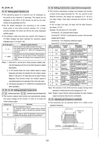
![Pr. 79-Pr. 145
Operation made selection
The inverter operation mode may be operated by external signal or
by the parameter unit. You may limit the operation mode to one of
these two modes, or you may use both modes.
Pr.71 must be set to either 20, 21, 22.
The following conditions are required for satisfactory operation
under magnetic flux control:
motor KW rating equal to or one size smaller than inverter
constant torque KW rating.
number of poles equal to 2, 4, or 6.
one motor per inverter (will not work with multiple motors)
wire length between inverter and motor not to exceed 100 Ft.
(30m).
Set value
I Set value 1 1Operation isenabledonly by the parameter unit. I
OperaGon is enabledby switchingbetween the parameter unit and the
externaloperation source(the factowsetvalue).
I Set value 2 1Operationisenabledonly by the externaloperationsource. 1 load characteristic requires high torque with some tolerance for
deviations from set frequency.
Motor Rated Voltage
Set the rated voltage for the motor in use.
Settings may be made between 0 and 1000V.
Note: Set these parameters when tuning upon selection of the auto-
tuning function.
Setvalue3r1)
Setvalue
IPr. 84 1 Motor Rated Frequency
Set the rated frequency for the motor in use.
Operationfrequency:Set by the parameterunit.
Start signal:Externalsignal is input.
Operationfrequency: Externalsignalisinput.
Start sianal:Inoutbv the Darameterunit.
Set value 5
Set value7
Set
Settings may be madebetween 50 and 1000Hz.
(Factory-set value is 60Hz)
Note: Set these parameters when tuning upon selection of the auto-
- . , .
Programoperation
Operationstart: STF; Timer reset:STR
Group selection:RH. RM, RL
Parameterunitoperationmode isprohibited.
Switchoverbetweenthe parameterunitand external operationmode is
possible.
With open-circuitingacross terminals RH and SD, the parametel
operationmode isselected.
With short-circuitingacross terminals RH and SD, the external
operationmode isselected.
Switchoveroperationis not availableduring the inverteroperating.
tuning function.
(Auto-Tunina SettinalStatus
dote : 1. In the parameter unitlexternal signal combined operatio1
mode, the followina sianals are made valid:
Set Value Operation Frequency Start Signal
.Directsettingand [A]/[r] key setting
Terminalsignal
Across 2-5 0 to 5VOC Forward rotationkey
Across 2-5 0 to lOVDC Reverse rotationkev
- - ..
In order to operate the motor at optimum characteristics under
magnetic flux vector control, the auto-tuning method may be used
to measure motor constancy.
During tuning, the Pr. 96 value will be displayed on the main
monitor and level meter sections ("3" or "103 will be displayed
.Across 4-5 4 to 20mADC
1 4 1.Across 1-5 0 to i5VDC
0 to ilOVDC
upon normal completion, and "9" upon faulty completion).
See oa. 17 for auto-tunina o~erationmethod.
Set value 1 Details
o INo auto-tunina (factowsettins).
I M U I ~ I - S ~ & ~selection
(Pr.4 to 6. 24 to 27)
The program operation function can set operation events
I
I - . . -.
1 IAuto-tuningwhen not operatingmotor. I
I 01 IAuto-tuningwhen operating motor. I
(Notes)
1. When motor is connected. However, turn off motor when
beginning to tune.
2. Auto-tuning is possible even when load (friction, normal load.
determining start time, rotation direction, and operation frequency
for each of the three selected groups. This function enables
automatic operation in accordance with the preset schedule and
pattern.
This function number can also be rewritten in the external
etc.) is coinected to the motor.
3. When selecting Pr.96 = "101" (auto-tuning when operating
motor), be careful because the motor is operating.
4. Tuning cannot be performed on high slip motors, high-speed
motors or other special type motors.
Refer to Pr.67.
Refer to Pr.14.
Parameter Unit Language Selection
0 Allows selection of the language displayed on the FR-PU02ERl
operation mode.
e With Pr. 79 set to 7, the parameter unit operation mode is
prohibited as described below, depending on terminal MRS signal.
I I forced. I
Setting Pr.11 to 8888 at external operation mode starts dc injection
FR-ARWER four-language parameter (copy) unit (option).
Parameter operation mode
Parameter unlt operationmode ispossible.
Settingparameterispossible.
Parameter unit operation mode and setting
parameterare impossible.
Switchover to external operation mode is
Across terminal
MRS and SD
ON
(close)
OFF
(open)
Set Value
brake operation
External
operation mode
Outputstop
External operation
mode ispassible.
LanguageDisplayed
0
1
2
Selecting Primary Magnetic Flux Control
IEnglish(factory setting)
German
French
Motor KW rating
3
No. of motor poles
Spanish 1
HP x ,746 = KW 120xF
Poles = ,p,
Note : This function is invalid when the FR-PU02, FR-PU02E or
I FR-ARW parameter (copy) unit used.
F = motor nameplatefrequency
rpm = motor nameplatebase speed
Select magnetic flux control mode operation by entering the motor
KW rating in parameter 80. Enter number of motor poles in
parameter 81. (factory settings of 9999 in Pr.80 and 81 selects V/
Hz mode).](https://image.slidesharecdn.com/fr-a140e-140613032109-phpapp02/85/Fr-a140-e-63-320.jpg)
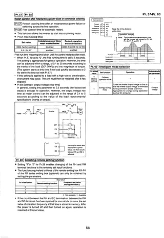
![IPr. 1551 RT Terminal Activation Timing Selection
The operation activated timing of the second control function
selection (terminal RT) may be selected.
Pr.155 set value 1 Second control function operation tirninq I
O IActivated immediately according to terminal RT ONIOFF
(factorysetting). I
Iduring acceleration/deceleration.) I
10
Note: "1" and "11" settings should be avoided, as they are special
settings performedexclusively by the manufacturer.
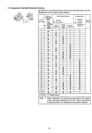
)I Stall PreventionOperationSelection
The oDerationdetails of the stall ~reventionfunction are selected.
Activatedontjwithterminal RT at'OWand atconstantspeed.
(Even with terminal RT at "ON, function not activated
IPr.156 set value I Stall prevention operation I
1 0 1Operates (factorysetting). I
Stall prevention does not operate during regenerative
operation.
Besides the above, various setting values may be selected. For
further details. refer to the o~erationinstructionmanual.
(1 Overload Alarm Signal Output Timer Setting
The overload alarm signal may be output when the time set in
Pr.157 is exceeded.
I]Refer to Pr.54.
Pr.157 set value
0 sec.
0.1-25 sec.
9999
I Pr. 900( Terminal FM output calibration
The parameter unit can be used to calibrate the meter connected
Output signal operation
0: OuQutaccordingto overload (OL)operation(factorysetting)
0.1-25: Output following set time.
9999: No overload alarm signal output.
to the FM terminal. This calibration function is common to all
monitorsselectedfor Pr.54.
Terminal FM has a pulse output as illustratedbelow. When Pr.900
is set, the parameter unit can be used to calibrate the scale of the
meterconnectedto the inverter,eliminatingthe use of a calibration
resistor. (For details of the calibration method, refer to the
instruction manual.)
Meter type: (1 mA full-scale analog meter).
I Meter W D ~ : 1
I (1mA full-scaleanalog meter)
TI r I
Pr.155 - Pr.905
Monitor by using the digital indicator
Pulsetrain output at the FMterminalcan be used for digital display
by the digital counter. The full-scale value described at Pr.54
provides 1440Hz output. When you select the operationfrequency
from monitoritems, the rate of output frequencyat this FMterminal
3
can be set for Pr.55.(Digitalindicator)
-,,!l,,,~- l",A
C
Pulse width TI: Adjusted by Pr. 900
Pulse width T2: Set by Pr. 55
(Dinelindicationmeter)
r
0 FM
SD
f'
L J
Note: The factory-setvalue providesthe full-scalevalue and 1440Hz
(Validonly for frequency monitor)
of FM output frequency at 60 Hz and ImA.
Terminal AM output calibration
This functionis usedfor calibrationwhen Pr.54has beenset to 101
- 118(or Pr.158 has beenset to 1-18) to selectanalog outputto AM
terminal. As described at Pr.54, the value has been factory-setso
that 10 VDC output is obtained with each monitor item in the full-
scale state. With this parameter,you can adjust the output voltage
rate (gain) to graduations of the meter. Note that the maximum
output voltage is 10 VDC. (For details on the calibration method,
refer to the instruction manual.)
1- pziqPr.903((Pr.9041]
Adjusting frequency setting signal gain and bias
IPr.902 I Bias for frequency referencevoltage signal
IPr.903 I Gain for frequency referencevoltage signal
Bias for frequency referencecurrent signal
Gain for frequency referencecurrent signal
You can set any value for the level of output frequency to the
frequency setting signal (0 to 5 VDC, or 0 to 10 VDC, or 4 to 20
mA).
A Factory-setvalue
(60Hz)
Output
frequency
Bias
I 0 Frequency setting signal 5V
0 1ov I](https://image.slidesharecdn.com/fr-a140e-140613032109-phpapp02/85/Fr-a140-e-64-320.jpg)
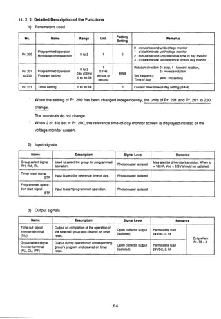
![4) Reference time of day
Programmed operation is performed under the control of the internal timer (RAM).
i) The timer range is 0 to 99.59.
When Pr. 200 = 0, max. 99 minutes 59 seconds
When Pr. 200 = 1, max. 99 hours 59 minutes
ii) Resetting the referencetime of day
Cleared by the timer reset terminal, inverter reset terminal or power-off.
iii) The reference time of day can be set in PR. 231 if required.
Can be used for synchronising]to the time of day.
iv) When Pr. 200 = 2 or 3, the reference time of day is displayed instead of voltage monitor.
v) Timer accuracy
Instantaneous error +0.16s
Accurnulative error (50ppm according to the accuracy of the crystal oscillator)
MT-A independent Error of max. 4.5s per day (24Hr X 60 X 60 X 50ppm 4.32s)
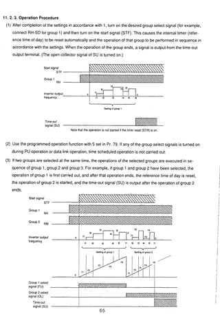
(3) Input terminals
0 The following terminals are made valid and invalid when programmed operation is being performed with
Pr. 79 = 5 (programmedoperation):
(4) Mode switching
When the programmed operation start signal (STF) or timer reset signal (STR) is on, switching between
the PU operation mode and external operation mode cannot be made.
Terminals Used
STF
STR
RH
RM
RL
Valid Terminals
RES
MRS
RT
OH
Invalid Terminals
AU
STOP
No. 2
No. 4
No. 1
JOG](https://image.slidesharecdn.com/fr-a140e-140613032109-phpapp02/85/Fr-a140-e-67-320.jpg)
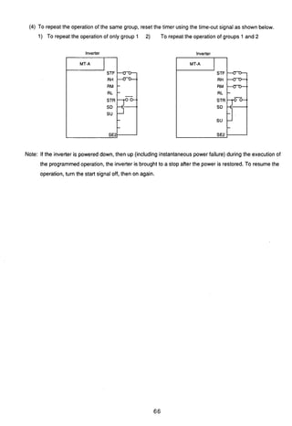
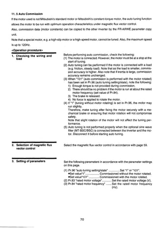
![4. Switching the auto commis-
sion command ON
In the PU operation mode, press the [FWD] or [REV] key.
In the external operation mode, turn on the start switch (connect
terminals across STF or STR-P24).
Note: 1. When "101" is set in Pr.96, be careful to avoid hazard
because the motor rotates.
2. During auto commission, the input terminals are made valid1
invalid as indicated below:
Valid Terminals Invalid Terminals
RWRMIRL
RT, JOG, CS 2. 1,4
STFISTR
*To force the motor to stop during tuning
Terminate commission using any of the MRS terminal, RES
terminal and [STOP] key.
5. Commission state monitoring During commissioning, the value of Pr.96 is displayed on the main
monitor and level meter of the PU as indicatedbelow. As on the PU, 1,
2,3,8,9,102 or 103 is shown on the inverter LED.
(When Pr.51 = "1" (factory setting))
*PU main monitor
*PU level meter
Indicatestuning progress with 0% (start) to full-scale 100% (end).
*Inverter LED
1. Setting
6. Auto commission end Check the value of Pr.96.
*Normal end ........" 3 or "10 3 is displayed.
*Forced end ........"8"is displayed.
*Error-activated end ........." 9is displayed.
3. Completion
2. Tuning in
Progress
When commissioncametoa normalendinthe PUoperationmode,pressthe I
[STOP] key. When in the external operation mode, turn off the start switch
(disconnect terminals STF or STR-P24). This operation resets auto
commission and returnsthe PUmonitorto anordinarydisplay.
r
/
Notethat if this operationis not performed,nextoperationcannot bestared.
Whentuningresultedinanerror-activatedend(Pr.96value=9)or aforcedend I
(Pr.96 value = 8), auto tuning did not come to a normal end and the motor ?
constant was not set. Inthis case, resetthe inverter(seepage 69) and restart f
from operationstep 1. 1
n,
vatedError-acti-End
Display
---Error-acti- 1vated End
- - - - - - - - - - - i
--- A
3. Completion
3--
-- 103
I.Setting
Displayed 0
value 101
I I I
1
--.<TOP PU
.
I I
101
--.STOP PU
2. Tuning in
Progress
-- 2
-- 102
-111111 1 I
TUNE 2
STF FIYD w
111111 I I
- , T U N E 1 0 2
S F FIVD PU
-](https://image.slidesharecdn.com/fr-a140e-140613032109-phpapp02/85/Fr-a140-e-76-320.jpg)
![[Optional Setting of Motor Constants]
The motor constants (Pr.90to 94) may either be set as appropriate by reading and changing the data measured by
gis.4~
auto commission, or without using the auto commission data:
3 H Setting the motor constants by reading and changing the auto commission data
<Operation procedure>
1. Change the set value of Pr.77 "parameterwrite disable selection" to "801".Only when the settings of Pr.80 and
Pr.81 are other than "9999, the parameters of the motor constants (Pr.90 to 94) can be displayed.
.& Though the parameters (Pr.82 to 99) other than the motor constants (Pr.90 to 94) may also be displayed, they
are to be set by the manufacturer and must therefore be set carefully without misoperation.
2. Set Pr.71 "applied motor" as indicated below:
Standard motor: Set "4". Constant-torque motor: Set "14".
3. In the parameter setting mode, read the following parameters and set the required values (Note 1):
4. Return the setting of Pr.77 to the original value.
Parameter Number
Pr.90
Pr.91
Pr.92
Pr.93
Pr.94
Note: 1. Only when the settings of Pr.80 and Pr.81 are other than "9999 (magnetic flux vector control is
selected), Pr.90 to 94 can be read.
2. Set "9999 in Pr.90 to 94 to use the standard motor constants (includingthe constant-torque motor).
3. Set "3" (standard motor) or "13 (constant-torque motor) in Pr.71 to use the motor constants
measured by auto tuning. If "4" or "14" has been set in Pr.71 and the motor constants changed, the
original data measured by auto commission remain changed.
4. The motor constants measured by auto tuning have been converted into internal data I****).
When setting the motor constants, see the following setting example:
Setting example: When the Pr.90 "motor constant R1" value displayed is 2516 and it is desired to
increase the Pr.90 value slightly (5%), set 2642 (i.e. 2516X 1.05 = 2641.8) in Pr.90. (The value
displayed has been converted into internaldata for internal use. Hence, there is no significance if an
optional value is simply added to the displayed value.)
Name
Motor constant R1
Motor constant R2
Motor constant L1
Motor constant L2
Motor constant 6
Setting Range (Note 4)
0 to "", 9999
0 to "**, 9999
0 to "", 9999
0 to "", 9999
0 to "", 9999
Minimum Setting
Increment
1
1
1
1
1
Factory Setting
9999
9999
9999
9999
9999](https://image.slidesharecdn.com/fr-a140e-140613032109-phpapp02/85/Fr-a140-e-77-320.jpg)
![Setting the motor constantswithout using the auto commission data
The motor constantsof Pr.92 and 93 may either be entered in [R]or [mH]. Check the unit of the motor constants
before starting the setting operation.
0
Entering the motor constants of Pr.92 and 93 in [R] /)
<Operation procedure>
1. Changethe set value of Pr.77"parameter write disableselection"to "801". Only when the settingsof Pr.80 and
Pr.81 are other than "9999, the parametersof the motor constants(Pr.90 to 94) can be displayed. Though the
parameters(Pr.82 to 99) other than the motor constants(Pr.90to 94) may also be displayed,they are to beset
by the manufacturer and must therefore be set carefully without misoperation.
2. Set Pr.71 "applied motor" as indicated below:
1 I Star Connection I Delta Connection
Motor Motor I
3. In the parameter setting mode, read the following parametersand set the requiredvalues:
.
f Pr.90 I Motor constant rl I 0 to 1OR. 9999 0.001a 9999 I
5
15
Set value
- - .
6
16
Standard motor
Constant-torque
motor
Pr-No.
4. Set Pr.84 "rated motor frequency" with reference to the following table:
b
-
I Pr.No. Name Range Increment I Factory Setting I
Name
Pr.91
Pr.92
Pr.93
Pr.94
Rated motor
frequency
5. Return the setting of Pr.77 to the original value.
Setting Range
Motor constant r2
Motor constant xi
Motor constant x2
Motor constant xm
Note: 1. Only when the settings of Pr.80 and Pr.81 are other than "9999 (magnetic flux vector control is
selected), Pr.90 to 94 can be read.
2. Set "9999 in Pr.90 to 94 to use the standard motor constants (includingthe constant-torquemotor).
3. If the "star connection" or "delta connectionnselected in Pr.71 does not match the actual motor,
proper magnetic flux vector control will not be carried out.
MinimumSetting
Increment
0 to 1OR, 9999
0 to 1on, 9999
0 to 1OR, 9999
0 to 5 0 0 ~9999
Factory Setting
0.001R
0.001R
0.001R
O.01R
9999
9999
9999
9999](https://image.slidesharecdn.com/fr-a140e-140613032109-phpapp02/85/Fr-a140-e-78-320.jpg)
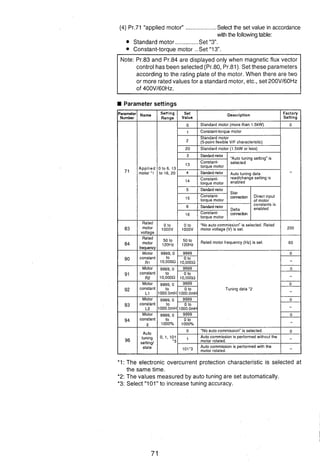
![Entering the motor constants of Pr.92 and 93 in [mH]
<Operation procedure>
1. Change the set value of Pr.77 "parameter write disable selection" to "801". Only when the settings of Pr.80 and
Pr.81 are other than "9999", the parametersof the motor constants (Pr.90 to 94) can be displayed. Though the
parameters (Pr.82 to 99) other than the motor constants (Pr.90 to 94) may also be displayed, they are to be set
by the manufacturer and must therefore be set carefully without misoperation.
5- 2. Set Pr.71 "applied motor" as indicated below:
Standard motor: Set "0.
Constant-torque motor: Set "1".
3. In the parameter setting mode, read the following parameters and set the required values:- .
I ! I I
I Pr.90
4. Set Pr.84 "rated motor frequency" with reference to the following table:
Pr.No.
I Motor constant R1 I 0 to 1OR, 9999
Pr.91
Pr.92
Pr.93
Pr.94
I Pr.No. Name Range Increment ( Factory Setting I
Setting RangeName
0.001R
Motor constant R2
Motor constant L1
Motor constant L2
Motor constantx
5. Return the setting of Pr.77 to the original value.
Minimum Setting
lncrement
9999
Pr.84
Note: 1. Only when the settings of Pr.80 and Pr.81 are other than "9999 (magnetic flux vector control is
selected), Pr.90 to 94 can be read.
2. Set "9999 in Pr.90 to 94 to use the standard motor constants or constant-torque motor constants.
Factory Setting
0 to 1OR, 9999
0 to IOOOmH, 9999
0 to 1000mH. 9999
0 to loo%, 9999
Rated motor
frequency
0.00112
0.1mH
O.lmH
0.1%
9999
9999
9999
9999
50 to 120Hz,9999 0.01Hz 9999](https://image.slidesharecdn.com/fr-a140e-140613032109-phpapp02/85/Fr-a140-e-79-320.jpg)
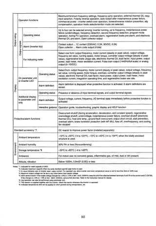
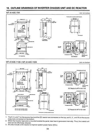
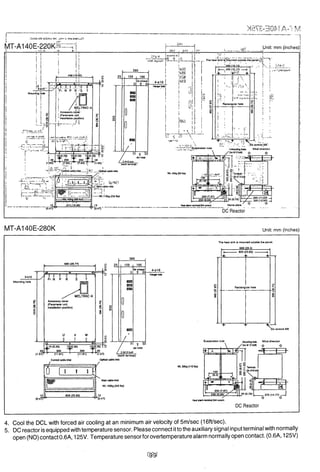
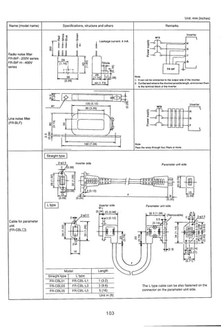


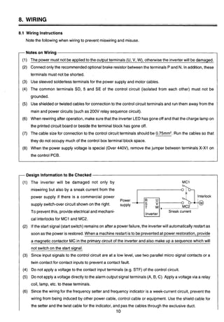
This document provides instructions and safety precautions for installing, operating, and maintaining an inverter chassis unit. Key points include: - Proper installation location and environment are important for cooling and to prevent dust/moisture from affecting operation. - Separate main circuit and control circuit wiring and minimize lengths if parallel. Ground shield cables at the inverter. - Directly ground the inverter enclosure to a ground bar or pole with a cable no smaller than 38mm^2. - Additional noise suppression measures may be needed depending on the application. - Verify power voltage is within the inverter's rated tolerance before operation.


![Ct2000 pro plus_manual_english[1]](https://cdn.slidesharecdn.com/ss_thumbnails/ct2000proplusmanualenglish1-140613213527-phpapp02-thumbnail.jpg?width=640&height=640&fit=bounds)

![Ct2000 es manual_english_version_1[1].0](https://cdn.slidesharecdn.com/ss_thumbnails/ct2000esmanualenglishversion11-140613213448-phpapp01-thumbnail.jpg?width=640&height=640&fit=bounds)


