Download to read offline

![A-1
Thank you for choosing this Mitsubishi Inverter.
4. Additional Instructions
Also note the following points to prevent an accidental failure, injury, electric
shock, etc.
This Instruction Manual provides instructions for advanced use of the FR-A700 series inverters.
Incorrect handling might cause an unexpected fault. Before using the inverter, always read this instruction manual and the instruction manual
(basic) [IB-0600225ENG] packed with the product carefully to use the equipment to its optimum.
This section is specifically about safety matters
Do not attempt to install, operate, maintain or inspect the inverter until you
have read through instruction manual (basic) and appended documents
carefully and can use the equipment correctly. Do not use the inverter until
you have a full knowledge of the equipment, safety information and
instructions. In this instruction manual, the safety instruction levels are
classified into "WARNING" and "CAUTION".
Assumes that incorrect handling may cause hazardous
conditions, resulting in death or severe injury.
Assumes that incorrect handling may cause
hazardous conditions, resulting in medium or slight
injury, or may cause physical damage only.
Note that even the level may lead to a serious consequence
according to conditions. Please follow strictly the instructions of both levels
because they are important to personnel safety.
1. Electric Shock Prevention
• While power is on or when the inverter is running, do not open the front cover.
Otherwise you may get an electric shock.
• Do not run the inverter with the front cover or wiring cover removed.
Otherwise, you may access the exposed high-voltage terminals or the charging
part of the circuitry and get an electric shock.
• Even if power is off, do not remove the front cover except for wiring or periodic
inspection.You may access the charged inverter circuits and get an electric shock.
• Before starting wiring or inspection, check to make sure that the operation panel
indicator is off, wait for at least 10 minutes after the power supply has been
switched off, and check that there are no residual voltage using a tester or the
like. The capacitor is charged with high voltage for some time after power off and
it is dangerous.
• This inverter must be earthed (grounded). Earthing (Grounding) must conform to
the requirements of national and local safety regulations and electrical codes.
(NEC section 250, IEC 536 class 1 and other applicable standards)
• Any person who is involved in the wiring or inspection of this equipment should
be fully competent to do the work.
• Always install the inverter before wiring. Otherwise, you may get an electric shock
or be injured.
• Perform setting dial and key operations with dry hands to prevent an electric
shock. Otherwise you may get an electric shock.
• Do not subject the cables to scratches, excessive stress, heavy loads or
pinching. Otherwise you may get an electric shock.
• Do not replace the cooling fan while power is on. It is dangerous to replace the
cooling fan while power is on.
• Do not touch the printed circuit board with wet hands. You may get an electric shock.
• When measuring the main circuit capacitor capacity, the DC voltage is applied to
the motor for 1s at powering off. Never touch the motor terminal, etc. right after
powering off to prevent an electric shock.
2. Fire Prevention
• Install the inverter on an incombustible wall without holes, etc.
Mounting it to or near combustible material can cause a fire.
• If the inverter has become faulty, switch off the inverter power.
A continuous flow of large current could cause a fire.
• When using a brake resistor, make up a sequence that will turn off power when
an alarm signal is output.
Otherwise, the brake resistor may excessively overheat due to damage of the
brake transistor and such, causing a fire.
• Do not connect the resistor directly to the DC terminals P/+ and N/-. This could cause
a fire.
3. Injury Prevention
• Apply only the voltage specified in the instruction manual to each terminal.
Otherwise, burst, damage, etc. may occur.
• Ensure that the cables are connected to the correct terminals. Otherwise, burst,
damage, etc. may occur.
• Always make sure that polarity is correct to prevent damage, etc. Otherwise,
burst, damage, etc. may occur.
• While power is on or for some time after power-off, do not touch the inverter as it
is hot and you may get burnt.
(1) Transportation and installation
• When carrying products, use correct lifting gear to prevent injury.
• Do not stack the inverter boxes higher than the number recommended.
• Ensure that installation position and material can withstand the weight of the
inverter. Install according to the information in the instruction manual.
• Do not install or operate the inverter if it is damaged or has parts missing. This can
result in breakdowns.
• When carrying the inverter, do not hold it by the front cover or setting dial; it may
fall off or fail.
• Do not stand or rest heavy objects on the product.
• Check the inverter mounting orientation is correct.
• Prevent other conductive bodies such as screws and metal fragments or other
flammable substance such as oil from entering the inverter.
• As the inverter is a precision instrument, do not drop or subject it to impact.
• Use the inverter under the following environmental conditions. Otherwise, the
inverter may be damaged.
WARNING
CAUTION
CAUTION
WARNING
CAUTION
CAUTION
CAUTION
Environment
Ambient temperature -10°C to +50°C (non-freezing)
Ambient humidity 90% RH or less (non-condensing)
Storage temperature -20°C to +65°C *1
Atmosphere
Indoors (free from corrosive gas, flammable
gas, oil mist, dust and dirt)
Altitude, vibration
Maximum 1000m above sea level for standard
operation. 5.9m/s2
or less *2
*1 Temperature applicable for a short time, e.g. in transit.
*2 2.9m/s2
or less for the 160K or more.
(2) Wiring
• Do not install a power factor correction capacitor or surge suppressor/radio
noise filter (capacitor type filter) on the inverter output side.
• The connection orientation of the output cables U, V, W to the motor will affect
the direction of rotation of the motor.
(3) Test operation and adjustment
• Before starting operation, confirm and adjust the parameters. A failure to do so
may cause some machines to make unexpected motions.
(4) Operation
• When you have chosen the retry function, stay away from the equipment as it
will restart suddenly after an alarm stop.
• Since the key is valid only when functions are set (refer to page 293),
provide a circuit and switch separately to make an emergency stop (power off,
mechanical brake operation for emergency stop, etc).
• Make sure that the start signal is off before resetting the inverter alarm. A failure
to do so may restart the motor suddenly.
• The load used should be a three-phase induction motor only. Connection of any
other electrical equipment to the inverter output may damage the inverter as well as
equipment.
• Performing pre-excitation (LX signal and X13 signal) under torque control (real
sensorless vector control) may start the motor running at a low speed even
when the start command (STF or STR) is not input. The motor may run also at a
low speed when the speed limit value = 0 with a start command input. Perform
pre-excitation after making sure that there will be no problem in safety if the
motor runs.
• Do not modify the equipment.
• Do not perform parts removal which is not instructed in this manual. Doing so
may lead to fault or damage of the inverter.
• The electronic thermal relay function does not guarantee protection of the motor
from overheating.
• Do not use a magnetic contactor on the inverter input for frequent starting/
stopping of the inverter.
• Use a noise filter to reduce the effect of electromagnetic interference. Otherwise
nearby electronic equipment may be affected.
• Take measures to suppress harmonics. Otherwise power supply harmonics from
the inverter may heat/damage the power factor correction capacitor and
generator.
• When a 400V class motor is inverter-driven, please use an insulation-enhanced
motor or measures taken to suppress surge voltages. Surge voltages
attributable to the wiring constants may occur at the motor terminals,
deteriorating the insulation of the motor.
• When parameter clear or all clear is performed, reset the required parameters
before starting operations. Each parameter returns to the initial value.
• The inverter can be easily set for high-speed operation. Before changing its
setting, fully examine the performances of the motor and machine.
• In addition to the inverter's holding function, install a holding device to ensure
safety.
• Before running an inverter which had been stored for a long period, always
perform inspection and test operation.
• For prevention of damage due to static electricity, touch nearby metal before
touching this product to eliminate static electricity from your body.
(5) Emergency stop
• Provide a safety backup such as an emergency brake which will prevent the
machine and equipment from hazardous conditions if the inverter fails.
• When the breaker on the inverter input side trips, check for the wiring fault (short
circuit), damage to internal parts of the inverter, etc. Identify the cause of the trip,
then remove the cause and power on the breaker.
• When the protective function is activated, take the corresponding corrective
action, then reset the inverter, and resume operation.
(6) Maintenance, inspection and parts replacement
• Do not carry out a megger (insulation resistance) test on the control circuit of the
inverter.
(7) Disposing of the inverter
• Treat as industrial waste.
General instructions
Many of the diagrams and drawings in this instruction manual show the inverter
without a cover, or partially open. Never run the inverter in this status. Always
replace the cover and follow this instruction manual when operating the
inverter.
CAUTION
CAUTION
WARNING
CAUTION
CAUTION
CAUTION
CAUTION](https://image.slidesharecdn.com/fr-a700-instruction-manual-applied-160425021934/85/Catalog-FR-A700-Instruction-manual-applied-Beeteco-com-3-320.jpg)


![22
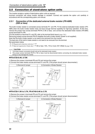
Main circuit terminal specifications
400V class (when input power supply is 440V)
The line voltage drop can be calculated by the following formula:
line voltage drop [V]=
Use a larger diameter cable when the wiring distance is long or when it is desired to decrease the voltage drop (torque
reduction) in the low speed range.
Applicable Inverter
Type
Terminal
Screw
Size *4
Tightening
Torque
N·m
Crimping
Terminal
Cable Sizes
HIV, etc. (mm2
) *1 AWG/MCM *2 PVC, etc. (mm2
) *3
R/L1,
S/L2,
T/L3
U, V, W
R/L1,
S/L2,
T/L3
U, V, W P/+, P1
Earth
(Ground)
Cable
R/L1,
S/L2,
T/L3
U, V, W
R/L1,
S/L2,
T/L3
U, V, W
Earth
(Ground)
Cable
FR-A740-0.4K to
3.7K
M4 1.5 2-4 2-4 2 2 2 2 14 14 2.5 2.5 2.5
FR-A740-5.5K M4 1.5 2-4 2-4 2 2 3.5 3.5 12 14 2.5 2.5 4
FR-A740-7.5K M4 1.5 5.5-4 5.5-4 3.5 3.5 3.5 3.5 12 12 4 4 4
FR-A740-11K M5 2.5 5.5-5 5.5-5 5.5 5.5 5.5 8 10 10 6 6 10
FR-A740-15K M5 2.5 8-5 8-5 8 8 8 8 8 8 10 10 10
FR-A740-18.5K M6 4.4 14-6 8-6 14 8 14 14 6 8 16 10 16
FR-A740-22K M6 4.4 14-6 14-6 14 14 22 14 6 6 16 16 16
FR-A740-30K M6 4.4 22-6 22-6 22 22 22 14 4 4 25 25 16
FR-A740-37K M8 7.8 22-8 22-8 22 22 22 14 4 4 25 25 16
FR-A740-45K M8 7.8 38-8 38-8 38 38 38 22 1 2 50 50 25
FR-A740-55K M8 7.8 60-8 60-8 60 60 60 22 1/0 1/0 50 50 25
FR-A740-75K M10 14.7 60-10 60-10 60 60 60 38 1/0 1/0 50 50 25
FR-A740-90K M10 14.7 60-10 60-10 60 60 80 38 3/0 3/0 50 50 25
FR-A740-110K M10-M12 14.7 80-10 80-10 80 80 80 38 3/0 3/0 70 70 35
FR-A740-132K M10-M12 14.7 100-10 100-10 100 100 100 38 4/0 4/0 95 95 50
FR-A740-160K M12-M10 24.5 150-12 150-12 125 150 150 38 250 250 120 120 70
FR-A740-185K M12-M10 24.5 150-12 150-12 150 150 150 38 300 300 150 150 95
FR-A740-220K M12-M10 24.5 100-12 100-12 2×100 2×100 2×100 60 2×4/0 2×4/0 2×95 2×95 95
FR-A740-250K M12-M10 24.5 100-12 100-12 2×100 2×100 2×125 60 2×4/0 2×4/0 2×95 2×95 95
FR-A740-280K M12-M10 24.5 150-12 150-12 2×125 2×125 2×125 60 2×250 2×250 2×120 2×120 120
FR-A740-315K M12-M10 24.5 150-12 150-12 2×150 2×150 2×150 100 2×300 2×300 2×150 2×150 150
FR-A740-355K M12-M10 24.5 C2-200 C2-200 2×200 2×200 2×200 100 2×350 2×350 2×185 2×185 2×95
FR-A740-400K M12-M10 24.5 C2-200 C2-200 2×200 2×200 2×200 100 2×400 2×400 2×185 2×185 2×95
FR-A740-450K M12-M10 24.5 C2-250 C2-250 2×250 2×250 2×250 100 2×500 2×500 2×240 2×240 2×120
FR-A740-500K M12-M10 24.5 C2-200 C2-250 3×200 2×250 3×200 2×100 2×500 2×500 2×240 2×240 2×120
*1 For the 55K or less, the cable size is that of the cable (HIV cable (600V class 2 vinyl-insulated cable) etc.) with continuous maximum permissible
temperature of 75°C. Assumes that the ambient temperature is 50°C or less and the wiring distance is 20m or less.
For the 75K or more, the recommended cable size is that of the cable (LMFC (heat resistant flexible cross-linked polyethylene insulated cable) etc.) with
continuous maximum permissible temperature of 90°C. Assumes that the ambient temperature is 50°C or less and wiring is performed in an enclosure.
*2 For the 45K or less, the recommended cable size is that of the cable (THHW cable) with continuous maximum permissible temperature of 75°C.
Assumes that the ambient temperature is 40°C or less and the wiring distance is 20m or less.
For the 55K or more, the recommended cable size is that of the cable (THHN cable) with continuous maximum permissible temperature of 90°C.
Assumes that the ambient temperature is 40°C or less and wiring is performed in an enclosure.
(Selection example for use mainly in the United States.)
*3 For the 45K or less, the recommended cable size is that of the cable (PVC cable) with continuous maximum permissible temperature of 70°C. Assumes
that the ambient temperature is 40°C or less and the wiring distance is 20m or less.
For the 55K or more, the recommended cable size is that of the cable (XLPE cable) with continuous maximum permissible temperature of 90°C.
Assumes that the ambient temperature is 40°C or less and wiring is performed in an enclosure.
(Selection example for use mainly in Europe.)
*4 The terminal screw size indicates the terminal size for R/L1, S/L2, T/L3, U, V, W, and a screw for earthing (grounding).
For the 110K and 132K, screw sizes are different (<R/L1, S/L2, T/L3, U, V, W, a screw for earthing (grounding)> - <P/+ for option connection>)
For the 160K or more, screw sizes are different. (<R/L1, S/L2, T/L3, U, V, W> - <a screw for earthing (grounding)>)
CAUTION
· Tighten the terminal screw to the specified torque.
A screw that has been tighten too loosely can cause a short circuit or malfunction.
A screw that has been tighten too tightly can cause a short circuit or malfunction due to the unit breakage.
· Use crimping terminals with insulation sleeve to wire the power supply and motor.
3 × wire resistance[mΩ/m] × wiring distance[m] × current[A]
1000](https://image.slidesharecdn.com/fr-a700-instruction-manual-applied-160425021934/85/Catalog-FR-A700-Instruction-manual-applied-Beeteco-com-33-320.jpg)


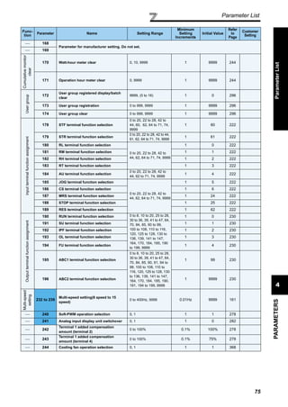
![60
Noise and leakage currents
1)Calculation of equivalent capacity P0 of harmonic generating equipment
The "equivalent capacity" is the capacity of a 6-pulse converter converted from the capacity of consumer's harmonic
generating equipment and is calculated with the following equation. If the sum of equivalent capacities is higher than
the limit in Table 3, harmonics must be calculated with the following procedure:
2)Calculation of outgoing harmonic current
Outgoing harmonic current = fundamental wave current (value converted from received power voltage) × operation
ratio × harmonic content
⋅Operation ratio: Operation ratio = actual load factor × operation time ratio during 30 minutes
⋅Harmonic content: Found in Table 4.
P0 = Σ (Ki × Pi) [kVA]
* Rated capacity: Determined by the capacity of the applied motor and
found in Table 5. It should be noted that the rated capacity used here
is used to calculate generated harmonic amount and is different from
the power supply capacity required for actual inverter drive.
Ki: Conversion factor(According to Table 2)
Pi: Rated capacity of harmonic generating equipment* [kVA]
i : Number indicating the conversion circuit type
Table 5 Rated capacities and outgoing harmonic currents of inverter-driven motors
Applied
Motor
(kW)
Rated Current
(A)
Fundamental
WaveCurrent
Converted
from 6.6kV
(mA)
Rated
Capacity
(kVA)
Outgoing Harmonic Current Converted from 6.6kV (mA)
(No reactor, 100% operation ratio)
200V 400V 5th 7th 11th 13th 17th 19th 23rd 25th
0.4 1.61 0.81 49 0.57 31.85 20.09 4.165 3.773 2.107 1.519 1.274 0.882
0.75 2.74 1.37 83 0.97 53.95 34.03 7.055 6.391 3.569 2.573 2.158 1.494
1.5 5.5 2.75 167 1.95 108.6 68.47 14.20 12.86 7.181 5.177 4.342 3.006
2.2 7.93 3.96 240 2.81 156.0 98.40 20.40 18.48 10.32 7.440 6.240 4.320
3.7 13.0 6.50 394 4.61 257.1 161.5 33.49 30.34 16.94 12.21 10.24 7.092
5.5 19.1 9.55 579 6.77 376.1 237.4 49.22 44.58 24.90 17.95 15.05 10.42
7.5 25.6 12.8 776 9.07 504.4 318.2 65.96 59.75 33.37 24.06 20.18 13.97
11 36.9 18.5 1121 13.1 728.7 459.6 95.29 86.32 48.20 34.75 29.15 20.18
15 49.8 24.9 1509 17.6 980.9 618.7 128.3 116.2 64.89 46.78 39.24 27.16
18.5 61.4 30.7 1860 21.8 1209 762.6 158.1 143.2 79.98 57.66 48.36 33.48
22 73.1 36.6 2220 25.9 1443 910.2 188.7 170.9 95.46 68.82 57.72 39.96
30 98.0 49.0 2970 34.7 1931 1218 252.5 228.7 127.7 92.07 77.22 53.46
37 121 60.4 3660 42.8 2379 1501 311.1 281.8 157.4 113.5 95.16 65.88
45 147 73.5 4450 52.1 2893 1825 378.3 342.7 191.4 138.0 115.7 80.10
55 180 89.9 5450 63.7 3543 2235 463.3 419.7 234.4 169.0 141.7 98.10
Applied
Motor
(kW)
Rated Current
(A)
Fundamental
WaveCurrent
Converted
from 6.6kV
(mA)
Rated
Capacity
(kVA)
Outgoing Harmonic Current Converted from 6.6kV (mA)
(With DC reactor, 100% operation ratio)
200V 400V 5th 7th 11th 13th 17th 19th 23rd 25th
75 245 123 7455 87.2 2237 969 626 373 350 239 224 164
90 293 147 8909 104 2673 1158 748 445 419 285 267 196
110 357 179 10848 127 3254 1410 911 542 510 347 325 239
132 — 216 13091 153 3927 1702 1100 655 615 419 393 288
160 — 258 15636 183 4691 2033 1313 782 735 500 469 344
220 — 355 21515 252 6455 2797 1807 1076 1011 688 645 473
250 — 403 24424 286 7327 3175 2052 1221 1148 782 733 537
280 — 450 27273 319 8182 3545 2291 1364 1282 873 818 600
315 — 506 30667 359 9200 3987 2576 1533 1441 981 920 675
355 — 571 34606 405 10382 4499 2907 1730 1627 1107 1038 761
400 — 643 38970 456 11691 5066 3274 1949 1832 1247 1169 857
450 — 723 43818 512 13146 5696 3681 2191 2060 1402 1315 964
500 — 804 48727 570 14618 6335 4093 2436 2290 1559 1462 1072](https://image.slidesharecdn.com/fr-a700-instruction-manual-applied-160425021934/85/Catalog-FR-A700-Instruction-manual-applied-Beeteco-com-71-320.jpg)


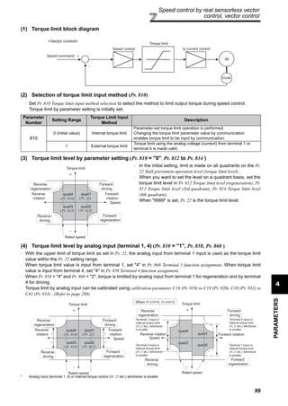
![69
Operation panel (FR-DU07)
4
PARAMETERS
4.1.2 Basic operation (factory setting)
At powering on (external operation mode)
PU operation mode
(output frequency monitor)
Parameter setting mode
PU Jog operation mode
Output current monitor Output voltage monitor
Display the current
setting
Value change
Value change
Parameter write is completed!!
Parameter and a setting value
flicker alternately.
Parameter clear All parameter
clear
Alarm clear
Parameter copy
(Example)
(Example)
Frequency setting has been
written and completed!!
and frequency flicker.
[Operation for displaying alarm history]
Past eight alarms can be displayed.
(The latest alarm is ended by ".".)
When no alarm history exists, is displayed.
Operation mode switchover
ParametersettingAlarmhistoryMonitor/frequencysetting
(Refer to page 383)
(Refer to page 70)](https://image.slidesharecdn.com/fr-a700-instruction-manual-applied-160425021934/85/Catalog-FR-A700-Instruction-manual-applied-Beeteco-com-80-320.jpg)


![107
Speed control by real sensorless vector
control, vector control
4
PARAMETERS
(6) When using a multi-pole motor (8 poles or more)
Specially when using a multi-pole motor with more than 8 poles under real sensorless vector control or vector control,
adjust Pr. 820 Speed control P gain 1 and Pr. 824 Torque control P gain 1 according to the motor referring to the following
methods.
· For Pr. 820 Speed control P gain 1, increasing the setting value improves the response level, but a too large gain will
produce vibration and/or unusual noise.
· For Pr. 824 Torque control P gain 1, note that a too low value will produce current ripples, causing the motor to generate
sound synchronizing the cycle of current ripples.
Adjustment method
(7) P/PI switchover (X44 signal)
· By turning the P/PI control switching signal (X44) on/off during seed control operation under real sensorless vector
control or vector control, you can select whether to add the integral time (I) or not when performing gain adjustment
with P gain and integral time.
When the X44 signal is off ............. PI control
When the X44 signal is on............. P control
· For the terminal used for X44 signal input, set "44" in any of Pr. 178 to Pr. 189 (input terminal function selection) to
assign the function.
[Function block diagram]
No. Phenomenon/Condition Adjustment Method
1
The motor rotation is unstable in the low
speed range.
Set a higher value in Pr. 820 Speed control P gain 1 according to the motor
inertia.
Since the self inertia of a multi-pole motor tends to become large, make
adjustment to improve the unstable phenomenon, then make fine adjustment
in consideration of the response level using that setting as reference.
In addition, when performing vector control with encoder, gain adjustment
according to the inertia can be easily done using easy gain tuning (Pr. 819 = 1).
2 Speed trackability is poor Set a higher value in Pr. 820 Speed control P gain 1.
Increase the value 10% by 10% until just before vibration or unusual noise is
produced, and set about 0.8 to 0.9 of that value.
If you cannot make proper adjustment, increase the value of Pr. 821 Speed
control integral time 1 double by double and make adjustment of Pr. 820 again.
3
Speed variation at the load fluctuation is
large
4
Torque becomes insufficient or torque
ripple occurs at starting or in the low
speed range under real sensorless vector
control.
Set the speed control gain a little higher. (same as No. 1)
If the problem still persists after gain adjustment, increase Pr. 13 Starting
frequency or set the acceleration time shorter if the inverter is starting to avoid
continuous operation in the ultra low speed range.
5
Unusual motor and machine vibration,
noise or overcurrent occurs. Set a lower value in Pr. 824 Torque control P gain 1.
Decrease the value 10% by 10% until just before the phenomenon is
improved, and set about 0.8 to 0.9 of that value.6
Overcurrent or overspeed (E.OS) occurs
at a start under real sensorless vector
control.
CAUTION
⋅ Changing the terminal assignment using Pr. 178 to Pr. 189 (input terminal function selection) may affect the other functions. Make
setting after confirming the function of each terminal.
+
-
Speed
command
Motor
X44 ON
X44 OFF
Integration
cleared to 0
+
+
0
Speed
command
Speed
proportional
operation
Speed
integral
operation
Torque
control
Speed estimator](https://image.slidesharecdn.com/fr-a700-instruction-manual-applied-160425021934/85/Catalog-FR-A700-Instruction-manual-applied-Beeteco-com-118-320.jpg)


![4
PARAMETERS
129
Position control by vector control
(2) Control block diagram
(3) Example of operation
The speed command given to rotate the motor is calculated to zero the difference between the number of internal
command pulse train pulses (when Pr. 419 = 0, the number of pulses set by parameter (Pr. 465 to Pr. 494) is changed to
the command pulses in the inverter) and the number of pulses fed back from the motor end encoder.
1)When a pulse train is input, pulses are accumulated in the deviation counter and these droop pulses act as position
control pulses to give the speed command.
2)As soon as the motor starts running under the speed command of the inverter, the encoder generates feed back
pulses and the droop of the deviation counter is counted down. The deviation counter maintains a given droop pulse
value to keep the motor running.
3)When the command pulse input stops, the droop pulses of the deviation counter decrease, reducing the speed. The
motor stops when there are no droop pulses.
4)When the number of droop pulses has fallen below the value set in Pr. 426 In-position width , it is regarded as
completion of positioning and the in-position signal (Y36) turns on.
⋅ For conditional position control function by contact input, the STF and STR terminals provide the forward (reverse)
command signal. The motor can run only in the direction where the forward (reverse) signal is on. Turning the STF
signal off does not run the motor forward and turning the STR signal off does not run the motor reverse.
⋅ The pulse train is rough during acceleration and coarse at the maximum speed. During deceleration the pulse train is
rough and at last there are no pulses. The motor stops shortly after the command pulses stop.
This time lag is necessary for maintaining the stop accuracy and called stop settling time.
REMARKS
⋅ For the servo on signal (LX), set "23" in Pr. 178 to Pr. 189 (input terminal function selection) to assign the function.
⋅ For the in-position signal (Y36), set "36" in Pr. 190 to Pr. 196 (output terminal function selection) to assign the function.
RH
RM
RL
REX
STF
STR
JOG
NP
Pr. 4 to 6
Pr. 24 to 27
Pr. 232 to 239
Pr.7
Pr. 465 to Pr. 494
travel Multi-speed,
communication 0
Pr. 419
Position command
source selection
2 Pr. 420
Pr. 421
Position command
acceleration/deceleration
time constant
Pr. 424
Position feed
forward
command filter
Pr. 425
Command pulse selection
Pr. 428
Electronic
gearCommand
pulse
Position feed
forward gain
Pr. 423
+
-
Deviation
counter
Position
loop gain
Pr. 422 +
+
Encoder
IM
Speed control
-
Clear signal
selection
Pr. 429 Differentiation
(Pr. 44, Pr. 110)(Pr. 45, Pr. 111)
Pr.8
Acceleration TimeDeceleration
Stop settling time
Motor speed
Pulse distribution
Droop pulse value
Pulse train Rough Fine Rough
LX signal
Servo on
STF (STR)
Forward (reverse)
Y36 signal
In-position signal
Commandpulsefrequency
[PPS]
Motorspeed[r/min]](https://image.slidesharecdn.com/fr-a700-instruction-manual-applied-160425021934/85/Catalog-FR-A700-Instruction-manual-applied-Beeteco-com-140-320.jpg)


![4
PARAMETERS
135
Position control by vector control
4.6.4 Setting of the electronic gear (Pr. 420, Pr. 421, Pr. 424)
(1) Calculation of the gear ratio (Pr. 420, Pr. 421)
⋅ The position resolution (travel per pulse Δ [mm]) is determined by the travel per motor revolution Δs [mm] and the
feedback pulses Pf [pulse/rev] of the detector, and is represented by the following expression.
Using the parameters, the travel per command pulse can be set separately to set the travel per command pulse
without a fraction.
In addition, the relationship between the motor speed and internal command pulse frequency is as follows:
Set the ratio of the machine side gear and the motor side gear.
Parameter
Number
Name Initial Value
Setting
Range
Description
420
Command pulse scaling
factor numerator
1 0 to 32767 *
Set the electric gear.
Pr. 420 is a numerator and Pr. 421 is a denominator.
421
Command pulse scaling
factor denominator
1 0 to 32767 *
424
Position command
acceleration/deceleration
time constant
0s 0 to 50s
Used when rotation has become unsmooth at a
large electronic gear ratio (about 10 times or more)
and low speed.
The above parameters can be set when the FR-A7AP (option) is mounted.
* When the operation panel (FR-DU07) is used, the maximum setting is 9999. When a parameter unit is used, up to the maximum value within
the setting range can be set.
Δ :travel per pulse [mm]
Δs: travel per motor rotation [mm]
Pf: number of feedback pulses [pulse/rev] (number of pulses after multiplying the number of
encoder pulses by four)
Δ =
Δs
Pf
Δ =
Δs
×
Pr. 420
Pf Pr. 421
fo ×
Pr. 420
= Pf ×
No fo : Internal command pulse frequency [pps]
Motor speed [r/min]Pr. 421 60 No :
CAUTION
Set the electronic gear in the range of 1/50 to 20.
Note that too small a value will decrease the speed command and too large a value will increase the speed ripples.
[Setting example 1]
The electronic gear ratio is Δs = 10 (mm) when the travel per pulse Δ = 0.01 (mm) and the number of feedback
pulses Pf = 4000 (pulse/rev) in a drive system where the ballscrew pitch PB = 10 (mm) and the reduction ratio 1/n = 1.
According to the following expression,
Therefore, set "4" in Pr. 420 and "1" in Pr. 421 .
[Setting example 2]
Find the internal command pulse frequency of the dedicated motor rated speed.
Note that the command pulse scaling factor Pr. 420/Pr. 421 = 1.
Assuming that the number of encoder pulses is 2048 (pulses/rev) (feedback pulse Pf = 2048 × 4),
Therefore, the internal command pulse frequency is 204800 (pps).
VectorVectorVector
Δ =
Δs
×
Pr. 420
Pf Pr. 421
Pr. 420
= Δ ×
Pf
Pr. 421 Δs
= 0.01 ×
4000
=
4
10 1
fo = 2048 ×
4
(multiplication)
×
No
×
Pr. 421
60 Pr. 420
= 204800](https://image.slidesharecdn.com/fr-a700-instruction-manual-applied-160425021934/85/Catalog-FR-A700-Instruction-manual-applied-Beeteco-com-146-320.jpg)
![136
Position control by vector control
Relationship between position resolution Δ and overall accuracy
Since overall accuracy (positioning accuracy of machine) is the sum of electrical error and mechanical error, normally
take measures to prevent the electrical system error from affecting the overall error. As a guideline, refer to the
following relationship.
<Stopping characteristic of motor>
When parameters are used to run the motor, the internal command pulse frequency and motor speed have the
relationship as shown in the chart on page 129, and as the motor speed decreases, pulses are accumulated in the
deviation counter of the inverter. These pulses are called droop pulses (ε) and the relationship between command
frequency (fo) and position loop gain (Kp: Pr. 422) is as represented by the following expression.
When the initial value of Kp is 25s-1
, the droop pulses (ε) are 8192 pulses.
Since the inverter has droop pulses during running, a stop settling time (ts) is needed from when the command has
zeroed until the motor stops. Set the operation pattern in consideration of the stop settling time.
When the initial value of Kp is 25s-1, the stop settling time (ts) is 0.12s.
The positioning accuracy Δε is (5 to 10) × Δ = Δε [mm]
(2) Position command acceleration/deceleration time constant (Pr. 424 )
⋅ When the electronic gear ratio is large (about 10 or more times) and the speed is low, rotation will not be smooth,
resulting in pulse-wise rotation. At such a time, set this parameter to smooth the rotation.
⋅ When acceleration/deceleration time cannot be provided for the command pulses, a sudden change in command
pulse frequency may cause an overshoot or error excess alarm. At such a time, set this parameter to provide
acceleration/deceleration time.
Normally set 0.
4.6.5 Setting of positioning adjustment parameter (Pr. 426, Pr. 427)
(1) In-position width (Pr. 426 )
The Y36 signal acts as an in-position signal.
When the number of droop pulses has fallen below the setting value, the in-position signal (Y36) turns on.
For the Y36 signal, assign the function by setting "36" (positive logic) or "136" (negative logic) in any of Pr. 190 to Pr.
196 (output terminal function selection) .
(2) Excessive level error (Pr. 427 )
When droop pulses exceed the value set in Pr. 427 , position error large occurs and displays an error (E.OD) to stop
the inverter. When you decreased the Pr. 422 Position loop gain setting, increase the error excessive level setting.
Also decrease the setting when you want to detect an error slightly earlier under large load.
When "9999" is set in Pr. 427 , position error large (E.OD) does not occur regardless of droop pulses.
Δ < ( 1
to
1
) × Δε Δε:positioning accuracy
5 10
ε =
fo
[pulse] ε =
204800
[pulse] (rated motor speed)
Kp 25
ts = 3 ×
1
[s]
Kp
♦Parameters referred to♦
Pr. 422 Position loop gain Refer to page 137
Parameter
Number
Name Initial Value Setting Range Description
426 In-position width 100 pulses 0 to 32767 pulses *
When the number of droop pulses has fallen below
the setting value, the in-position signal (Y36) turns on.
427 Excessive level error 40K
0 to 400K
A position error excessive (E.OD) occurs when the
number of droop pulses exceeds the setting.
9999 Function invalid
The above parameters can be set when the FR-A7AP (option) is mounted.
* When the operation panel (FR-DU07) is used, the maximum setting is 9999. When a parameter unit is used, up to the maximum value within
the setting range can be set.
VectorVectorVector](https://image.slidesharecdn.com/fr-a700-instruction-manual-applied-160425021934/85/Catalog-FR-A700-Instruction-manual-applied-Beeteco-com-147-320.jpg)


![141
Adjustment of real sensorless vector
control, vector control
4
PARAMETERS
4.7.2 Excitation ratio (Pr. 854)
Decrease the excitation ratio when you want to improve efficiency under light load. (Motor magnetic noise
decreases.)
Parameter
Number
Name Initial Value Setting Range Description
854 Excitation ratio 100% 0 to 100% Set the excitation ratio under no load.
⋅ Note that the rise of output torque becomes slow if
excitation ratio is decreased.
This function is appropriate for applications as machine
tools which repeat rapid acceleration/deceleration up to
high speed.
REMARKS
⋅ When "1" (magnetic flux with terminal) is set in Pr. 858 Terminal 4 function assignment or Pr. 868 Terminal 1 function assignment, the
Pr. 854 setting is made invalid.
SensorlessSensorlessSensorlessSensorlessSensorlessSensorlessSensorlessSensorlessSensorless VectorVectorVector
Excitation
ratio [%]
100
(initial value)
Pr. 854
set value
0 100 Load [%]](https://image.slidesharecdn.com/fr-a700-instruction-manual-applied-160425021934/85/Catalog-FR-A700-Instruction-manual-applied-Beeteco-com-152-320.jpg)


![147
Adjust the output torque of the motor (current)
4
PARAMETERS
4.8.3 Slip compensation (Pr. 245 to Pr. 247)
⋅ Slip compensation is validated when the motor rated slip calculated by the following formula is set in Pr. 245. Slip
compensation is not made when Pr. 245 = "0" or "9999".
The inverter output current may be used to assume motor slip to keep the motor speed constant.
Parameter
Number
Name Initial Value Setting Range Description
245 Rated slip 9999
0.01 to 50% Used to set the rated motor slip.
0, 9999 No slip compensation
246
Slip compensation time
constant
0.5s 0.01 to 10s
Used to set the slip compensation response
time. When the value is made smaller,
response will be faster. However, as load
inertia is greater, a regenerative overvoltage
(E.OV ) error is more liable to occur.
247
Constant-power range slip
compensation selection
9999
0
Slip compensation is not made in the
constant power range (frequency range
above the frequency set in Pr. 3)
9999
Slip compensation is made in the constant
power range.
Rated slip =
Synchronous speed at base frequency - rated speed
× 100[%]
Synchronous speed at base frequency
REMARKS
When performing slip compensation, the output frequency may become greater than the set frequency. Set the Pr. 1 Maximum
frequency value a little higher than the set frequency.
♦ Parameters referred to ♦
Pr. 1 Maximum frequency Refer to page 153
Pr. 3 Base frequency Refer to page 155
V/FV/FV/F](https://image.slidesharecdn.com/fr-a700-instruction-manual-applied-160425021934/85/Catalog-FR-A700-Instruction-manual-applied-Beeteco-com-158-320.jpg)

![149
Adjust the output torque of the motor (current)
4
PARAMETERS
(2) Stall prevention operation signal output and output timing adjustment (OL signal, Pr. 157)
⋅ When the output power exceeds the stall prevention operation level and stall prevention is activated, the stall
prevention operation signal (OL signal) turns on for longer than 100ms. When the output power falls to or below the
stall prevention operation level, the output signal turns off.
⋅ Use Pr. 157 OL signal output timer to set whether the OL signal is output immediately or after a preset period of time.
⋅ This operation is also performed when the regeneration avoidance function (overvoltage stall) is executed.
(3) Setting of stall prevention operation in high frequency range (Pr. 22, Pr. 23, Pr. 66)
⋅ During high-speed operation above the rated motor frequency, acceleration may not be made because the motor
current does not increase. If operation is performed in a high frequency range, the current at motor lockup
becomes smaller than the rated output current of the inverter, and the protective function (OL) is not executed if the
motor is at a stop.
To improve the operating characteristics of the motor in this case, the stall prevention level can be reduced in the
high frequency range. This function is effective for performing operation up to the high-speed range on a centrifugal
separator etc. Normally, set 60Hz in Pr. 66 and 100% in Pr. 23.
⋅ Formula for stall prevention operation level
⋅ When Pr. 23 Stall prevention operation level compensation factor at double speed = "9999" (initial value), the stall
prevention operation level is kept constant at the Pr. 22 setting up to 400Hz.
Pr. 157 Setting Description
0
(initial value)
Output immediately
0.1 to 25 Output after the set time (s) has elapsed
9999 Not output
REMARKS
⋅ The OL signal is assigned to the terminal OL in the initial setting. The OL signal can also be assigned to the other terminal by
setting "3 (positive logic) or 103 (negative logic)" to any of Pr. 190 to Pr. 196 (output terminal function selection).
CAUTION
· If the frequency has fallen to 0.5Hz by stall prevention operation and remains for 3s, an alarm (E.OLT) appears to shutoff the
inverter output.
· When terminal assignment is changed using Pr. 190 to Pr. 196 (output terminal function selection), the other functions may be
affected. Please make setting after confirming the function of each terminal.
Stall prevention operation level in
high frequency range (%)
= A + B × [
Pr. 22 - A
] × [
Pr. 23 - 100
]
Pr. 22 - B 100
However, A =
Pr. 66(Hz) × Pr. 22(%)
, B =
Pr. 66(Hz) × Pr. 22(%)
Output frequency (H) 400Hz
Overload state
(OL operation)
OL output signal
Pr.157 Set time(s)
Output frequency (Hz)
Pr. 22
When Pr. 23 = 9999
Pr. 66 400Hz
Stallpreventionoperation
level(%)
Stall prevention operation level
as set in Pr. 23
When Pr. 23 = "9999", the stall prevention
operation level is as set in Pr. 22 to 400Hz.
150
90
60
45
30
22.5
600 100 200 300 400
Output frequency (Hz)
Setting example (Pr.22=150%, Pr.23=100%, Pr.66=60Hz)
Stallpreventionoperationlevel(%)](https://image.slidesharecdn.com/fr-a700-instruction-manual-applied-160425021934/85/Catalog-FR-A700-Instruction-manual-applied-Beeteco-com-160-320.jpg)


![163
Frequency setting by external terminals
4
PARAMETERS
4.11.2 Jog operation (Pr. 15, Pr. 16)
The above parameters are displayed as simple mode parameters only when the parameter unit (FR-PU04/FR-PU07) is connected. When the
operation panel (FR-DU07) is connected, the above parameters can be set only when Pr. 160 User group read selection = "0". (Refer to page 296)
* When the setting of Pr. 21 Acceleration/deceleration time increments is "0" (initial value), the setting range is "0 to 3600s" and the setting increments are
"0.1s", and when the setting is "1", the setting range is "0 to 360s" and the setting increments are "0.01s"
(1) Jog operation from outside
⋅ When the jog signal is on, a start and stop can be made by the start signal (STF, STR). (The jog signal is assigned
to the terminal JOG in the initial setting)
You can set the frequency and acceleration/deceleration time for jog operation. Jog operation can be performed
from either the outside or PU.
Can be used for conveyor positioning, test operation, etc.
Parameter
Number
Name
Initial
Value
Setting Range Description
15 Jog frequency 5Hz 0 to 400Hz Set the frequency for jog operation.
16
Jog
acceleration/
deceleration
time
0.5s 0 to 3600/360s*
Set the acceleration/deceleration time for jog operation. Set the
time taken to reach the frequency (Initial value is 60Hz) set in Pr. 20
Acceleration/deceleration reference frequency for acceleration/
deceleration time.
The acceleration and deceleration time cannot be set separately.
REMARKS
⋅ When you want to change the running frequency, change Pr. 15 Jog frequency . (initial value "5Hz")
⋅ When you want to change the acceleration/deceleration time change Pr. 16 Jog acceleration/deceleration time . (initial value
"0.5s")
Output
frequency(Hz)
Pr.20
Pr.15
Jog frequency
setting range
Pr.16
Forward
rotation
Reverse
rotation
Time
ON
ON
ON
JOG signal
Forward
rotation STF
Reverse
rotation STR
STF
10
2
5
JOG
Motor
Inverter
R/L1
S/L2
T/L3
U
V
W
Connection diagram for external jog operation
STR
Three-phase AC
power supply
Forward rotation start
Reverse rotation start
JOG signal
SD
1.Screen at powering on
Confirm that the external operation mode is selected.
([EXT] lit)
If not displayed, press to change to the
external [EXT] operation mode.
If the operation mode still does not change,
set Pr. 79 to change to the external operation mode.
IndicationOperation
2.Turn the JOG switch on.
ON
Forward
rotation
Forward
rotation
Reverse
rotation
Reverse
rotation
Rotates while ON
Stop
3.Turn the start switch (STF or STR) on.
The motor rotates while start switch
(STF or STR) is ON.
Rotates at 5Hz. (Initial value of Pr. 15)
4.Turn the start switch (STF or STR) off.
ON
OFF](https://image.slidesharecdn.com/fr-a700-instruction-manual-applied-160425021934/85/Catalog-FR-A700-Instruction-manual-applied-Beeteco-com-174-320.jpg)
![164
Frequency setting by external terminals
(2) Jog operation from PU
⋅ Set the PU (FR-DU07/FR-PU07/FR-PU04) to the
jog operation mode. Operation is performed only
while the start button is pressed.
CAUTION
⋅ When Pr. 29 Acceleration/deceleration pattern selection= "1" (S-pattern acceleration/deceleration A), the acceleration/deceleration
time is the period of time required to reach Pr. 3 Base frequency.
⋅ The Pr. 15 setting should be equal to or higher than the Pr. 13 Starting frequency setting.
⋅ The JOG signal can be assigned to the input terminal using any of Pr. 178 to Pr. 189 (input terminal function selection). When terminal
assignment is changed, the other functions may be affected. Please make setting after confirming the function of each terminal.
⋅ During jog operation, the second acceleration/deceleration via the RT signal cannot be selected. (The other second functions
are valid. (Refer to page 226))
⋅ When Pr. 79 Operation mode selection = "4", push / of the PU (FR-DU07/FR-PU04/FR-PU07) to make a start or push
to make a stop.
⋅ This function is invalid when Pr. 79 = "3" or "6".
⋅ Jog operation is invalid under position control.
♦ Parameters referred to ♦
⋅ Pr. 13 Starting frequency Refer to page 170
⋅ Pr. 29 Acceleration/deceleration pattern selection Refer to page 171
⋅ Pr. 20 Acceleration/deceleration reference frequency, Pr. 21 Acceleration/deceleration time increments Refer to page 168
⋅ Pr. 79 Operation mode selection Refer to page 298
⋅ Pr. 178 to Pr. 189 (input terminal function selection) Refer to page 222
Motor
Inverter
R/L1
S/L2
T/L3
U
V
W
FR-DU07
Three-phase AC
power supply
1.
2.
6.
7.
8.
5.
9.
10.
IndicationOperation
Stop
The parameter
number read
previously
appears.
Press to choose the
PU JOG operation mode.
3.Press (or ).
4.Release (or ).
The monitor mode should have been selected.
The inverter should be at a stop.
While (or ) is pressed, the
motor rotates.
Rotates at 5Hz. (initial value of Pr. 15)
Hold down.
Press to set.
Flicker Parameter setting complete!!
Release
Press to choose the parameter
setting mode.
Perform the operations in steps 1 to 4.
The motor rotates at 10Hz.
Turn until Pr. 15 JOG frequency
appears.
Turn to set the value to
" ". (10Hz)
Press to show the currently set
value. (5Hz)
Confirmation of the RUN indication and
operation mode indication
[When changing the frequency of PU JOG
operation]](https://image.slidesharecdn.com/fr-a700-instruction-manual-applied-160425021934/85/Catalog-FR-A700-Instruction-manual-applied-Beeteco-com-175-320.jpg)


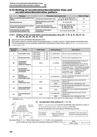


![171
Setting of acceleration/deceleration time
and acceleration/deceleration pattern
4
PARAMETERS
4.12.3 Acceleration/deceleration pattern (Pr. 29, Pr. 140 to Pr. 143, Pr. 380 to Pr. 383,
Pr. 516 to Pr. 519)
You can set the acceleration/deceleration pattern suitable for application.
You can also set the backlash measures that stop acceleration/deceleration once at the parameter-set frequency
and time during acceleration/deceleration.
Parameter
Number
Name
Initial
Value
Setting
Range
Description
29
Acceleration/deceleration pattern
selection
0
0 Linear acceleration/ deceleration
1 S-pattern acceleration/deceleration A
2 S-pattern acceleration/deceleration B
3 Backlash measures
4 S-pattern acceleration/deceleration C
5 S-pattern acceleration/deceleration D
140 Backlash acceleration stopping frequency 1Hz 0 to 400Hz
Set the stopping frequency and time for
backlash measures.
Valid when Pr. 29 = 3
141 Backlash acceleration stopping time 0.5s 0 to 360s
142 Backlash deceleration stopping frequency 1Hz 0 to 400Hz
143 Backlash deceleration stopping time 0.5s 0 to 360s
380 Acceleration S-pattern 1 0 0 to 50% Valid when S-pattern acceleration/
deceleration C (Pr. 29 = 4) is set.
Set the time taken for S-pattern from
starting of acceleration/deceleration to
linear acceleration as % to the
acceleration/deceleration time (Pr. 7, Pr. 8
etc.).
An acceleration/deceleration pattern can
be changed with the X20 signal.
381 Deceleration S-pattern 1 0 0 to 50%
382 Acceleration S-pattern 2 0 0 to 50%
383 Deceleration S-pattern 2 0 0 to 50%
516 S-pattern time at a start of acceleration 0.1s 0.1 to 2.5s
Valid when S-pattern acceleration/
deceleration D (Pr. 29 = 5) is set.
Set the time taken for S-pattern
acceleration/deceleration (S-pattern
operation).
517
S-pattern time at a completion of
acceleration
0.1s 0.1 to 2.5s
518 S-pattern time at a start of deceleraiton 0.1s 0.1 to 2.5s
519
S-pattern time at a completion of
deceleraiton
0.1s 0.1 to 2.5s
(1) Linear acceleration/ deceleration (Pr. 29 = "0", initial value)
⋅ When the frequency is changed for acceleration, deceleration, etc. in inverter
operation, the output frequency is changed linearly (linear acceleration/
deceleration) to reach the set frequency without straining the motor and inverter.
Linear acceleration/deceleration has a uniform frequency/time slope.
(2) S-pattern acceleration/deceleration A (Pr. 29 = "1")
⋅ For machine tool spindle applications, etc.
Used when acceleration/deceleration must be made in a short time to a high-
speed range of not lower than the base frequency. In this acceleration/
deceleration pattern, Pr. 3 Base frequency (fb) is the inflection point of the S
pattern and you can set the acceleration/deceleration time appropriate for motor
torque reduction in a constant-power operation region of Pr. 3 Base frequency
(initial value = 60Hz) or higher.
CAUTION
⋅ As the acceleration/deceleration time of S-pattern acceleration/deceleration A, set the time taken until Pr. 3 Base frequency is
reached, not Pr. 20 Acceleration/deceleration reference frequency.
Setting value "0"
[Linear acceleration
/ deceleration]
Outputfrequency
(Hz)
Time
fb
Outputfrequency
(Hz)
Setting value "1"
Time
[S-pattern acceleration
/deceleration A]](https://image.slidesharecdn.com/fr-a700-instruction-manual-applied-160425021934/85/Catalog-FR-A700-Instruction-manual-applied-Beeteco-com-182-320.jpg)
![172
Setting of acceleration/deceleration time
and acceleration/deceleration pattern
(3) S-pattern acceleration/deceleration B (Pr. 29 = "2")
⋅ For prevention of load shifting in conveyor and other applications
Since acceleration/deceleration is always made in an S shape from current
frequency (f2) to target frequency (f1), this function eases shock produced at
acceleration/deceleration and is effective for load collapse prevention, etc.
(4) Backlash measures (Pr. 29 = "3", Pr. 140 to Pr. 143)
⋅ What is backlash?
Reduction gears have an engagement gap and have a dead zone between forward
rotation and reverse rotation. This dead zone is called backlash, and this gap disables
a mechanical system from following motor rotation.
More specifically, a motor shaft develops excessive torque when the direction of
rotation changes or when constant-speed operation shifts to deceleration, resulting in
a sudden motor current increase or regenerative status.
⋅ To avoid backlash, acceleration/deceleration is temporarily stopped.
Set the acceleration/deceleration stopping frequency and time in Pr. 140 to Pr. 143.
CAUTION
Setting the backlash measures increases the acceleration/deceleration time by the stopping time.
(5) S-pattern acceleration/deceleration C (Pr. 29 =
"4", Pr. 380 to Pr. 383)
⋅ With the S-pattern acceleration/deceleration C switch
signal (X20), an acceleration/deceleration curve S-pattern 1
or S-pattern 2 can be selected.
⋅ For the terminal used for X20 signal input, set "20" in any of
Pr. 178 to Pr. 189 (input terminal function selection) to assign
the function.
Parameter setting (%) Ts / T × 100% ⋅ Set % of time taken for forming an S-pattern in Pr. 380 to Pr.
383 as acceleration time is 100%.
CAUTION
⋅ Change the S pattern acceleration/deceleration C switch (X20 signal) after the speed becomes constant.
⋅ S pattern operation before switching continues even if the X20 signal is changed during acceleration or deceleration.
⋅ The X20 signal can be assigned to the input terminal using any of Pr. 178 to Pr. 189 (input terminal function selection). Changing
the terminal assignment may affect the other functions. Make setting after confirming the function of each terminal.
f1
Setting value "2"
[S-pattern acceleration
/deceleration B]
f2
Time
Setfrequency
(Hz)
Outputfrequency
(Hz)
Pr. 142
Pr. 143Pr. 141
Pr. 140
Pr. 13
Outputfrequency(Hz)
[Anti-backlash measure
function]
Setting value "3"
Time
Pr.382
Pr.383
Pr.381
S-pattern
acceleration/
deceleration
C switchover
(X20)
OFF OFFON
Output frequencyOutput frequencyOutput frequency
Set frequencySet frequencySet frequency
Pr.380
Frequency
Time
Operation
X20 signal
During
Acceleration
During
Deceleration
OFF
Pr. 380 Acceleration S-
pattern 1
Pr. 381 Deceleration
S-pattern 1
ON
Pr. 382 Acceleration S-
pattern 2
Pr. 383 Deceleration
S-pattern 2
S-pattern
acceleration
Linear
acceleration
Ts
T
Ts
REMARKS
⋅ At a start, the motor starts at Pr. 13 Starting frequency when the
start signal turns on.
⋅ If there is a difference between the speed command and speed
at a start of deceleration due to torque limit operation etc., the
speed command is matched with the speed to make
deceleration.](https://image.slidesharecdn.com/fr-a700-instruction-manual-applied-160425021934/85/Catalog-FR-A700-Instruction-manual-applied-Beeteco-com-183-320.jpg)


![176
Selection and protection of a motor
4.13 Selection and protection of a motor
4.13.1 Motor protection from overheat (Electronic thermal relay function) (Pr. 9, Pr. 51)
*1 The initial value of the 0.4K and 0.75K is set to 85% of the rated inverter current.
*2 When parameter is read using the FR-PU04, a parameter name different from an actual parameter is displayed.
(1) Electronic thermal relay function operation characteristic (THM)
Purpose Parameter that must be Set Refer to Page
Motor protection from overheat Electronic thermal O/L relay Pr. 9, Pr. 51 176
Use the constant torque motor Applied motor Pr. 71 180
The motor performance can be
maximized for operation in magnetic
flux vector control system
Offline auto tuning
Pr. 82 to Pr. 84,
Pr. 90 to Pr. 94, Pr. 96
182
High accuracy operation unaffected
by the motor temperature and stable
operation with high torque down to
ultra low speed are performed
Online auto tuning Pr. 95, Pr. 574 192
Set the current of the electronic thermal O/L relay to protect the motor from overheat. This feature provides the
optimum protective characteristics, including reduced motor cooling capability, at low speed.
Parameter
Number
Name Initial Value Setting Range Description
9
Electronic thermal
O/L relay
Ratedinverter
current *1
55K or less 0 to 500A
Set the rated motor current.
75K or more 0 to 3600A
51
Second electronic
thermal O/L relay *2
9999
55K or less 0 to 500A Made valid when the RT signal is on.
Set the rated motor current.75K or more 0 to 3600A
9999
Second electronic thermal O/L relay
invalid
[Electronic thermal relay function operation characteristic (E.THM)] This function detects the overload (overheat) of the
motor, stops the operation of the inverter's output
transistor, and stops the output. (The operation
characteristic is shown on the left)
⋅ Set the rated current [A] of the motor in Pr. 9. (When
the power supply specification is 200V/220V(400V/
440V) 60Hz, set the 1.1 times the rated motor current.)
⋅ Set "0" in Pr. 9 when you do not want to activate the
electronic thermal relay function, e.g. when using an
external thermal relay with the motor. (Note that the
output transistor protection of the inverter functions
(E.THT).)
⋅ When using the Mitsubishi constant-torque motor
1) Set "1" or any of "13" to "18", "50", "53", "54" in Pr. 71.
(This provides a 100% continuous torque characteristic
in the low-speed range.)
2) Set the rated current of the motor in Pr. 9.
*1 When a value 50% of the rated inverter current (current value) is
set in Pr. 9
*2 The % value denotes the percentage to the rated inverter current. It
is not the percentage to the motor rated current.
*3 When you set the electronic thermal relay function dedicated to the
Mitsubishi constant-torque motor, this characteristic curve applies
to operation at 6Hz or higher.
CAUTION
⋅ Protective function by electronic thermal relay function is reset by inverter power reset and reset signal input. Avoid
unnecessary reset and power-off.
⋅ When multiple motors are operated by a single inverter, protection cannot be provided by the electronic thermal relay function.
Install an external thermal relay to each motor.
⋅ When the difference between the inverter and motor capacities is large and the setting is small, the protective characteristics of
the electronic thermal relay function will be deteriorated. In this case, use an external thermal relay.
⋅ A special motor cannot be protected by the electronic thermal relay function. Use the external thermal relay.
Electronic thermal relay
function for transistor
protection
52.5% 105%
50 100 150
60
120
180
240
50
60
70
6Hz
20Hz
10Hz
6Hz
0.5Hz
30Hz or more*3
20Hz
10Hz
0.5Hz
Pr. 9 = 50% setting of
inverter rating*1.2
Pr. 9 = 100% setting
of inverter rating*2
(s)unitdisplayinthisregion
(min)unitdisplayin
thisregion
Operationtime(min)Operationtime(s)
Characteristic when
electronic thermal relay
function for motor
protection is turned off
(When Pr. 9 setting is 0(A))
30Hz
or more*3
Ration of the motor current to
Pr. 9 Electronic thermal relay function (%)
Operation region
Region on the right of
characteristic curve
Non-operation region
Region on the left of
characteristic curve](https://image.slidesharecdn.com/fr-a700-instruction-manual-applied-160425021934/85/Catalog-FR-A700-Instruction-manual-applied-Beeteco-com-187-320.jpg)
![177
Selection and protection of a motor
4
PARAMETERS
(2) Electronic thermal relay function operation characteristic (THT)
Electronic thermal relay function (transistor protection thermal) operation characteristics of the inverter when the ratio
of the motor current to the inverter rated current is presented as transverse is shown. Transverse is calculated as
follows: (motor current [A]/inverter rated current [A]) × 100 [%].
Optimum Conditions
Inverter Capacity
55K or less 75K or more
Running frequency : 1Hz or more
Carrier frequency: 2kHz
Running frequency : 1Hz or less
Carrier frequency: 2kHz
CAUTION
⋅ Protective function by electronic thermal relay function is reset by inverter power reset and reset signal input. Avoid
unnecessary reset and power-off.
⋅ The operation time of the transistor protection thermal relay shortens when the Pr. 72 PWM frequency selection setting increases.
⋅ Since a thermal protector is built in a motor dedicated for vector control (SF-V5RU), set "0" in Pr. 9 to use the motor.
0
30
60
90
120
150
0 25 50 75 100 125 150 175 200
Ratio of the motor current
to the inverter rated current (%)
Operationtime(S)
0
30
60
90
120
150
0 25 50 75 100 125 150 175 200
Ratio of the motor current
to the inverter rated current (%)Operationtime(S)
0
3
6
9
12
15
0 25 50 75 100 125 150 175 200
Ratio of the motor current
to the inverter rated current (%)
Operationtime(S)
0
3
6
9
12
15
0 25 50 75 100 125 150 175 200
Ratio of the motor current
to the inverter rated current (%)
Operationtime(S)](https://image.slidesharecdn.com/fr-a700-instruction-manual-applied-160425021934/85/Catalog-FR-A700-Instruction-manual-applied-Beeteco-com-188-320.jpg)


![189
Selection and protection of a motor
4
PARAMETERS
(5) Method to set the motor constants without using the offline auto tuning data
The Pr. 92 and Pr. 93 motor constants may either be entered in [Ω] or in [mH]. Before starting operation, confirm which
motor constant unit is used.
• To enter the Pr. 92 and Pr. 93 motor constants in [Ω]
<Operating procedure>
1) Set Pr. 71 according to the motor used.
2) In the parameter setting mode, read the following parameters and set desired values.
3)Refer to the following table and set Pr. 83 and Pr. 84 .
* The initial value differs according to the voltage level. (200V/400V)
Star Connection
Motor
Delta Connection
Motor
Setting
Standard motor 5 6
Constant-torque motor 15 16
Parameters
Number
Name Setting Range
Setting
Increments
Initial
Value
82
Motor excitation current
(no load current)
55K or less 0 to 500A, 9999 0.01A
9999
75K or more 0 to 3600A, 9999 0.1A
90 Motor constant (r1)
55K or less 0 to 50Ω, 9999 0.001Ω
9999
75K or more 0 to 400mΩ, 9999 0.01mΩ
91 Motor constant (r2)
55K or less 0 to 50Ω, 9999 0.001Ω
9999
75K or more 0 to 400mΩ, 9999 0.01mΩ
92 Motor constant (x1)
55K or less 0 to 50Ω, 9999 0.001Ω
9999
75K or more 0 to 3600mΩ, 9999 0.01mΩ
93 Motor constant (x2)
55K or less 0 to 50Ω, 9999 0.001Ω
9999
75K or more 0 to 3600mΩ, 9999 0.01mΩ
94 Motor constant (xm)
55K or less 0 to 500Ω, 9999
0.01Ω 9999
75K or more 0 to 100Ω, 9999
859 Torque current
55K or less 0 to 500A, 9999 0.01A
9999
75K or more 0 to 3600A, 9999 0.1A
Parameter
Number
Name Setting Range
Setting
Increments
Initial
Value
83 Motor rated voltage 0 to 1000V 0.1V 200V/400V
84 Rated motor frequency 10 to 120Hz 0.01Hz 60Hz
REMARKS
· When "9999" is set in Pr. 82, Pr. 90 to Pr. 94, Pr. 859, Mitsubishi motor (SF-JR, SF-HR,SF-JRCA, SF-HRCA, SF-V5RU) constants
are used.
CAUTION
· If "star connection" is mistaken for "delta connection" or vice versa during setting of Pr. 71, advanced magnetic flux vector
control, real sensorless vector control and vector control cannot be exercised properly.
Iq = I1002 - I02
Iq = torque current, I100 = rated current, I0 = no load current](https://image.slidesharecdn.com/fr-a700-instruction-manual-applied-160425021934/85/Catalog-FR-A700-Instruction-manual-applied-Beeteco-com-200-320.jpg)
![190
Selection and protection of a motor
• To enter the Pr. 92 and Pr. 93 motor constants in [mH]
<Operating procedure>
1) Set Pr. 71 according to the motor used.
*1 For other settings of Pr. 71, refer to the page 180.
2) In the parameter setting mode, read the following parameters and set desired values.
Calculate the Pr. 94 value from the following formula.
3)Refer to the following table and set Pr. 83 and Pr. 84 .
* The initial value differs according to the voltage level. (200V/400V)
Motor Pr.71 Setting*
Mitsubishi standard
motor
Mitsubishi high
efficiency motor
SF-JR 0
SF-JR 4P 1.5kW or less 20
SF-HR 40
Mitsubishi constant-
torque motor
SF-JRCA 4P
SF-TH (constant torque)
1
SF-HRCA 4P 50
Vector control
dedicated motor
SF-V5RU 30
Pr. 94 setting = (1 -
M2
) × 100 (%)
L1 × L2
Motor equivalent circuit diagram
Parameter
Number
Name Setting Range
Setting
Increments
Initial
Value
82
Motor excitation current
(no load current)
55K or less 0 to 500A, 9999 0.01A
9999
75K or more 0 to 3600A, 9999 0.1A
90 Motor constant (R1)
55K or less 0 to 50Ω, 9999 0.001Ω
9999
75K or more 0 to 400mΩ, 9999 0.01mΩ
91 Motor constant (R2)
55K or less 0 to 50Ω, 9999 0.001Ω
9999
75K or more 0 to 400mΩ, 9999 0.01mΩ
92 Motor constant (L1)
55K or less 0 to 1000mH, 9999 0.1mH
9999
75K or more 0 to 400mH, 9999 0.01mH
93 Motor constant (L2)
55K or less 0 to 1000mH, 9999 0.1mH
9999
75K or more 0 to 400mH, 9999 0.01mH
94 Motor constant (X)
55K or less 0 to 100%, 9999 0.1%
9999
75K or more 0 to 100%, 9999 0.01%
859 Torque current
55K or less 0 to 500A, 9999 0.01A
9999
75K or more 0 to 3600A, 9999 0.1A
Parameter
Number
Name Setting Range
Setting
Increments
Initial
Value
83 Motor rated voltage 0 to 1000V 0.1V 200V/400V
84 Rated motor frequency 10 to 120Hz 0.01Hz 60Hz
REMARKS
· When "9999" is set in Pr. 82, Pr. 90 to Pr. 94, Pr. 859, Mitsubishi motor (SF-JR, SF-HR,SF-JRCA, SF-HRCA, SF-V5RU)
constants are used.
L1= I1+ M: Primary inductance
L2= I2+ M: Secondary inductance
MV R2/S
R1 I1 I2
R1: Primary resistance
I1: Primary leakage inductance
I2: Secondary leakage inductance
M: Excitation inductance
S: Slip
R2: Secondary resistance](https://image.slidesharecdn.com/fr-a700-instruction-manual-applied-160425021934/85/Catalog-FR-A700-Instruction-manual-applied-Beeteco-com-201-320.jpg)


![198
Motor brake and stop operation
4.14.2 Selection of regenerative brake and DC feeding (Pr. 30, Pr. 70)
<55K or less>
When making frequent starts/stops, use the optional high-duty brake resistor (FR-ABR), brake unit (FR-BU2,
BU, FR-BU, MT-BU) to increase the regenerative brake duty.
Use a power regeneration common converter (FR-CV) or power regeneration converter (MT-RC) for continuous
operation in regenerative status.
Use a high power factor converter (FR-HC, MT-HC) to reduce harmonics, improve the power factor, or
continuously use the regenerative mode.
You can select either DC feeding mode 1 in which operation is performed with DC power (terminal P/+, N/-) or
DC feeding mode 2 in which operation is performed normally with the AC power (terminal R/L1, S/L2, T/L3) and
performed with DC power such as battery at occurrence of power failure.
Parameter
Number
Name
Initial
Value
Setting Range Description
30
Regenerative function
selection
0
Regeneration unit
Terminal for power
supply to the inverter
0
Built-in brake resistor, without
regenerative function, brake
unit (FR-BU2 [other than MT-
BU5 mode], FR-BU, BU type)
R/L1, S/L2, T/L3
10
P/+, N/-
(DC feeding mode 1)
20
R/L1, S/L2, T/L3 - P/+, N/-
(DC feeding mode 2)
1
High-duty brake resistor, brake
unit (FR-BU2 [MT-BU5 mode],
MT-BU5), power regeneration
converter (MT-RC)
R/L1, S/L2, T/L3
11
P/+, N/-
(DC feeding mode 1)
21
R/L1, S/L2, T/L3 - P/+, N/-
(DC feeding mode 2)
2
High power factor converter
(FR-HC, MT-HC), power
regeneration common
converter (FR-CV)
P/+, N/-
70
Special regenerative
brake duty
0%
55K or less 0 to 30%
Set the %ED of the built-in brake transistor operation.
75K or more 0 to 10%
Regeneration Unit
Power Supply to
the Inverter
Pr. 30
Setting
Pr. 70
Setting
Remarks
Built-in brake (7.5K or less),
brake unit (FR-BU2, FR-BU, BU)
R/L1, S/L2, T/L3
0
(initial value)
⎯
The regenerative brake duty is as follows.
⋅ FR-A720-0.4K to 3.7K . . . . . 3%
⋅ FR-A720-5.5K, 7.5K . . . . . . . 2%
⋅ FR-A740-0.4K to 7.5K . . . . . 2%
⋅ Other than the above . . . . . . 0%
(without built-in brake resistor)
P/+, N/- 10
R/L1, S/L2, T/L3 -
P/+, N/-
20
High-duty brake resistor (FR-ABR)
(22K or less)
R/L1, S/L2, T/L3 1
10/6%
Change the setting according to the
capacity.
(7.5K or less / 11K or more)
P/+, N/- 11
R/L1, S/L2, T/L3 -
P/+, N/-
21
High power factor converter (FR-HC),
power regeneration common
converter (FR-CV)
P/+, N/- 2
0
(initial value)](https://image.slidesharecdn.com/fr-a700-instruction-manual-applied-160425021934/85/Catalog-FR-A700-Instruction-manual-applied-Beeteco-com-209-320.jpg)
![199
Motor brake and stop operation
4
PARAMETERS
<75K or more>
(1) When the built-in brake resistor, the brake unit (FR-BU2 [other than MT-BU5 mode], BU, FR-
BU) is used
⋅ Set "0 (initial value), 10 or 20" in Pr. 30. The Pr. 70 setting is made invalid.
At this time, the regenerative brake duty is as follows. (The built-in brake resistor is provided for the 7.5K or less.)
⋅ FR-A720-0.4K to 3.7K .......3%
⋅ FR-A720-5.5K, 7.5K ......... 2%
⋅ FR-A740-0.4K to 7.5K ...... 2%
⋅ Other than the above........ 0% (without built-in brake resistor)
(2) When using the high-duty brake resistor (FR-ABR) (22K or less)
⋅ Set "1, 11 or 21" in Pr. 30.
⋅ Set Pr. 70 as follows.
7.5K or less............................ 10%
11K or more ............................. 6%
(4) When using the high power factor converter (FR-HC, MT-HC) or power regeneration
common converter (FR-CV)
⋅ Set "2" in Pr. 30. The Pr. 70 setting is made invalid.
⋅ Use any of Pr. 178 to Pr. 189 (input terminal function assignment) to assign the following signals to the contact input
terminals.
(a)X10 signal: FR-HC, MT-HC connection, FR-CV connection (inverter operation enable signal)
To make protective coordination with the FR-HC, MT-HC or FR-CV, use the inverter operation enable signal
to shut off the inverter output. Input the RDY signal of the FR-HC, MT-HC (RDYB signal of the FR-CV).
(b)X11 signal: FR-HC, MT-HC connection (instantaneous power failure detection signal)
When the setting has been made to hold the mode at occurrence of an instantaneous power failure for RS-
485 communication operation, use this signal to hold the mode. Input the Y1 or Y2 signal (instantaneous
power failure detection signal) of the FR-HC, MT-HC.
⋅ For the terminal used for X10 or X11 signal input, assign its function by setting "10" (X10) or "11" (X11) in any of Pr.
178 to Pr. 189.
Regeneration Unit
Power Supply to the
Inverter
Pr. 30
Setting
Pr. 70
Setting
Brake unit
(FR-BU2 [other than MT-BU5 mode])
R/L1, S/L2, T/L3
0
(initial value)
⎯
P/+, N/- 10
R/L1, S/L2, T/L3 - P/+, N/- 20
Power regeneration converter (MT-RC) R/L1, S/L2, T/L3 1
0%
(initial value)
Brake unit
(FR-BU2 [MT-BU5 mode], MT-BU5)
R/L1, S/L2, T/L3 1
10%P/+, N/- 11
R/L1, S/L2, T/L3 - P/+, N/- 21
High power factor converter (FR-HC) P/+, N/- 2 ⎯
CAUTION
⋅ When replacing the existing MT-BU5 type brake unit with the FR-BU2 type brake unit, set "2" in Pr. 0 Brake mode selection of the
FR-BU2, "1" in Pr. 30 Regenerative function selection and "10%" in Pr. 70 Special regenerative brake duty of the inverter.
⋅ Do not operate the MT-BU5 type brake unit and FR-BU2 in parallel. Doing so could cause an alarm or brake unit failure. Use
the FR-BU2 only when performing parallel operation.
(3) When using a brake unit (FR-BU2 [MT-BU5 mode], MT-BU5) and power regeneration
converter (MT-RC)
⋅ Set "1, 11 or 21" in Pr. 30.
⋅ Set "10%" in Pr. 70 when using a brake unit (FR-BU2 [MT-BU5 mode], MT-BU5).
⋅ Set "0%" in Pr. 70 when using a power regeneration converter (MT-RC).](https://image.slidesharecdn.com/fr-a700-instruction-manual-applied-160425021934/85/Catalog-FR-A700-Instruction-manual-applied-Beeteco-com-210-320.jpg)


![203
Motor brake and stop operation
4
PARAMETERS
(7) Power supply specification at DC feeding
(8) Regenerative brake duty alarm output and alarm signal (RBP signal)
200V class
Rated input DC voltage 283VDC to 339VDC
Permissible fluctuation 240VDC to 373VDC
400V class
Rated input DC voltage 537VDC to 679VDC
Permissible fluctuation 457VDC to 740VDC
CAUTION
⋅ As voltage between P/+, N/- becomes 415V (830V) or more temporarily at regeneration, make selection of DC power supply
carefully.
100%: regenerative overvoltage protection operation value ⋅ [RB] appears on the operation panel and an alarm signal (RBP) is
output when 85% of the regenerative brake duty set in Pr. 70 is
reached. If the regenerative brake duty reaches 100% of the Pr.
70 setting, a regenerative overvoltage (E.OV1 to E.OV3) occurs.
⋅ The inverter does not shut off the output when the alarm signal is
output.
⋅ For the terminal used for the RBP signal output, assign the
function by setting "7" (positive logic) or "107" (negative logic) in
any of Pr. 190 to Pr. 196 (output terminal function selection).
REMARKS
⋅ The MRS signal can also be used instead of the X10 signal. (Refer to page 225.)
⋅ Refer to pages 42 to 51 for the connection of high-duty brake resistor (FR-ABR), brake unit, high power factor converter (FR-HC,
MT-HC) and power regeneration common converter (FR-CV).
⋅ When AC power is connected to terminal R/L1, S/L2, T/L3 during DC feeding with "2, 10 or 11" (DC feeding) set in Pr. 30, an
option alarm (E.OPT) occurs.
⋅ When DC feeding operation is performed with "2, 10, 11, 20, or 21" (DC deeding) set in Pr. 30, undervoltage protection (E.UVT)
and instantaneous power failure (E.IPF) are not detected.
CAUTION
⋅ The brake resister is not connectable to the 30K or more inverter, the Pr. 70 setting is invalid.
⋅ Changing the terminal assignment using Pr. 178 to Pr. 189 (input terminal function selection) or Pr. 190 to Pr. 196 (output terminal
function selection) may affect the other functions. Please make setting after confirming the function of each terminal. (Refer to page
222)
WARNING
The value set in Pr. 70 must not exceed the setting of the brake resistor used.
Otherwise, the resistor can overheat.
♦ Parameters referred to ♦
Pr. 57 Restart coasting time Refer to page 255
Pr. 178 to Pr.189 (input terminal function selection) Refer to page 222
Pr. 190 to Pr.196 (output terminal function selection) Refer to page 230
Pr. 261 Power failure stop selection Refer to page 259
Ratio of brake duty
to the Pr. 70 setting
Regenerative
brake prealarm
(RBP) OFF ON
100%
85%
Time
ON](https://image.slidesharecdn.com/fr-a700-instruction-manual-applied-160425021934/85/Catalog-FR-A700-Instruction-manual-applied-Beeteco-com-214-320.jpg)


![214
Motor brake and stop operation
(3) Selecting stop position command (Pr. 350 Stop position command selection )
⋅ Select either the internal stop position command (Pr. 356) or the external stop position command (16-bit data using
the FR-A7AX).
2)External stop position command (Pr. 350 = "1")
Mount the option FR-A7AX and set a stop position using 16-bit data (binary input).
⋅ The value set in Pr. 360 16 bit data selection should be the number of stop positions less 1.
Pr. 350 Setting Stop Position Command Source
0 Internal stop position command (Pr. 356: 0 to 16383)
1 External stop position command (FR-A7AX) 16-bit data
9999
(Initial value)
Orientation control invalid
1)Internal stop position command (Pr. 350 = "0")
The value set in Pr. 356 is the stop position.
When the number of encoder pulses is 1024p/r, one
revolution of the encoder is divided into 4096 positions,
i.e. 360°/4096 pulses = 0.0879°/pulses per address, as
shown on the right. The stop positions (addresses) are
indicated in parentheses.
Pr. 360 Setting Description
0 External position command is made invalid (speed command or torque command with the FR-A7AX)
1
Position command direct input
The 16-bit digital signal from the FR-A7AX is directly serves as stop position command.
<Example>
When the Pr. 369 Number of encoder pulses setting is 1024, stop position command from 0 to 4095 can be
directly input using the FR-A7AX and input digital signal of 2048 (H800) to stop the motor at 180° position. The
command more than 4096 is considered as 4095.
2 to 127
Set the stop position command dividing up to 128 stop positions at regular intervals.
If the external stop command entered is greater than the setting, the stop positions are the same as those in
the maximum external stop command value.
<Example>
When the number of stop positions is 90 (divided at intervals of 4°), 90 - 1 = 89. Hence, set "89".
[Example] When Pr. 369 = "1024" [Example 2] 8 stop positions [Example 3] 120 stop positions
Pr. 360 = "1" Pr. 360 = "7" Pr. 360 = "119"
CAUTION
⋅ Values in parentheses indicate binary data entered from the terminals. Even if the position pulse monitor (Pr. 52 DU/PU main
display data selection = 19) is selected, the data monitored is not the number of stop positions but is 0 to 65535 pulses.
⋅ FR-A7AX parameters (Pr. 300 to Pr. 305) are invalid. (Valid when Pr. 360 = "0")
⋅ Terminal DY (data read timing input signal) is made invalid during vector control. (The position data is downloaded at the start of
orientation.)
⋅ Internal stop position command is given even if "1" (external stop position command) is set in Pr. 350 when an option card (FR-
A7AX) is not mounted or Pr. 360 = "0".
Origin (0) Origin (0)
CW CCW
270
(3072)
90
(1024)
Pr. 359 = 1
270
(3072)
180 (2048)
Pr. 359 = 1
180 (2048)
90
(1024)
270
(3072(HC00))
180
(2048(H800))
90
(1024(H400))
CW
Origin (0) Origin(0)(7 or more)
315
(6)270
(5)225
(1)
45
135
(3)180
(4)
90
(2)
CW
Origin (0)
CW
At intervals
of 3
270
(90)
180
(60)
90
(30)](https://image.slidesharecdn.com/fr-a700-instruction-manual-applied-160425021934/85/Catalog-FR-A700-Instruction-manual-applied-Beeteco-com-225-320.jpg)


![219
Motor brake and stop operation
4
PARAMETERS
Position loop gain (Pr. 362 )
When servo torque function is selected using Pr. 358 Servo torque selection , output frequency for generating servo
torque increases to the creep speed of Pr. 352 Creep speed gradually according to the slope set in Pr. 362 Orientation
position loop gain .
Although the operation becomes faster when the value is increased, a machine may hunt, etc.
(7) Orientation operation explanation (during vector control)
Setting the rotation direction (Pr. 393 Orientation selection )
1)Orientation from the current rotation direction
2)Orientation from the forward rotation direction
Pr. 393 Setting
Rotation
Direction
Remarks
0
(initial value)
Pre-orientation Orientation is executed from the current rotation direction.
1
Forward rotation
orientation
Orientation is executed from the forward rotation direction.
(If the motor is running in reverse, orientation is executed from the
forward rotation direction after deceleration.)
2
Reverse rotation
orientation
Orientation is executed from the reverse rotation direction.
(If the motor is running in forward, orientation is executed from the
reverse rotation direction after deceleration.)
• When the orientation command (X22) is input, the motor speed will
decelerate from the runnig speed to Pr. 351 Orientation speed.
At the same time, the orientation stop position command will be read in.
(The stop position command is determined by the setting of Pr. 350 and Pr.
360. Refer to the right chart.)
• When the orientation switchover speed is reached, the encoder Z phase
pulse will be confirmed, and the mode will change from speed control to
position control (Pr. 362 Orientation position loop gain ).
• The distance to the orientation stop position is calculated at switching of
the control, and the motor decelerates and stops with a set deceleration
pattern (Pr. 399) and the orientation (servo lock) state will be entered.
• When entered in the Pr. 357 Orientation in-position zone, the orientation
completion signal (ORA) will be output.
• The zero point position (origin) can be moved using Pr. 361 Position shift .
WARNING
If the orientation command (X22) is turned off while the start signal is input, the motor will accelerate toward the
speed of the current speed command. Thus, to stop, turn the forward rotation (reverse rotation) signal off.
• This method is used to improve the stopping precision and maintain the
mechanical precision when the backlash is large.
• If the motor is running in the forward rotation direction, it will make an
orientation stop with the same method as "orientation from the current
rotation direction".
• If the motor is running in reverse, it will decelerate, the rotation direction
will be changed to forward run, and then orientation stop will be executed.
OFF ONX22
Speed
(forward rotation)
OFF ONORA
[t]
OFF ONX22
Speed
(reverse rotation)
OFF ONORA
[t]
Speed
(forward rotation)
X22
ORA
[t]
Speed
(reverse rotation)
X22
ORA
[t]](https://image.slidesharecdn.com/fr-a700-instruction-manual-applied-160425021934/85/Catalog-FR-A700-Instruction-manual-applied-Beeteco-com-230-320.jpg)
![220
Motor brake and stop operation
3)Orientation from the reverse rotation direction
Servo rigidity adjustment (Pr. 362, Pr. 396 to Pr. 398)
•To increase the servo rigidity *1 during orientation stop using Pr. 396 or Pr. 397 , adjust with the following procedures.
1) Increase the Pr. 362 Orientation position loop gain value to the extent that rocking *2 does not occur during
orientation stop.
2) Increase Pr. 396 and Pr. 397 at the same rate.
Generally adjust Pr. 396 in the range from 10 to 100, and Pr. 397 from 0.1 to 1.0s.
(Note that these do not need to be set to the same rate.)
<Example>
When the Pr. 396 value is multiplied by 1.2, divide the Pr. 397 value by 1.2.
If vibration occurs during orientation stop, the scale cannot be raised any higher.
3) Pr. 398 is the lag/advance compensation gain.
The limit cycle *3 can be prevented by increasing the value, and the running can be stopped stably. However, the
torque in regard to the position deviation will drop, and the motor will stop with deviation.
*1 Servo rigidity: This is the response when a position control loop is configured.
When the servo rigidity is raised, the holding force will increase, the running will stabilize, but vibration will occur easily.
When the servo rigidity is lowered, the holding force will drop, and the setting time will increase.
*2 Rocking: Movement in which return occurs if the stopping position is exceeded.
*3 Limit cycle: This is a phenomenon that generates ± continuous vibration centering on the target position.
• If the motor is running in the reverse rotation direction, it will make an
orientation stop with the same method as "orientation from the current
rotation direction".
• If the motor is running in forward, it will decelerate, the rotation direction
will be changed to reverse run, and then orientation stop will be executed.
CAUTION
• The encoder should be coupled with the motor shaft oriented with a speed ratio of 1 to 1 without any mechanical looseness.
• To ensure correct positioning, the encoder must be set in the proper rotation direction and the A and B phases connected
correctly.
• Orientation may not be completed if the pulse signals are not received from the encoder during orientation due to a break in the
cable or the like.
• To terminate orientation, the start signal (STF or STR) must be first switched off and the orientation signal (X22) must be switched
off. As soon as this orientation signal is switched off, orientation control ends.
• When performing orientation control, make proper setting of Pr. 350 Stop position command selection and Pr. 360 16 bit data selection.
If the values set are incorrect, proper orientation control will not be performed.
• When orientation control is exercised, PID control is invalid.
REMARKS
If "E.ECT" (no encoder signal) is displayed causing the inverter to trip when the orient signal (X22) is ON, check for a break in the
cable of the Z phase of the encoder.
POINT
Application of lag/advance control and PI control
PI control can be applied by setting Pr. 398 to 0. Normally, the lag/advance control is selected. Note that PI control
shoud be used when using a machine with a high spindle stationary friction torque and requires a stopping position
precision.
Speed
(forward rotation)
X22
ORA
[t]
Speed
(reverse rotation)
X22
ORA
[t]](https://image.slidesharecdn.com/fr-a700-instruction-manual-applied-160425021934/85/Catalog-FR-A700-Instruction-manual-applied-Beeteco-com-231-320.jpg)
![221
Motor brake and stop operation
4
PARAMETERS
Pr. 399 Orientation deceleration ratio (initial value is 20)
• Make adjustments as shown below according to the orientation status.
(Refer to the Pr. 396 and Pr. 397 details also.)
Generally adjust Pr. 362 in the range from 5 to 20, and Pr. 399 from 5 to 50.
Pr. 351 Orientation speed (initial value: 2Hz)
• Set the speed when switching beween the speed control mode and the position control mode is performed under
orientation operation.
Decreasing the set speed enables stable orientation stop. Note that the orientation time will increase.
Phenomenon
Adjustment Procedure
Pr. 396 Pr. 397 Pr. 362 Pr. 399
Rocking occurs during
stopping
3) 3) 2) 1)
The orientation time is long 2) 1)
Hunting occurs when
stopping
2) 2) 1)
The servo rigidity during
stopping is low
1) 1) 2)
CAUTION
Or, if the motor does forward/reverse reciprocation operation , the parameter setting value for the orientation detector
installation direction may be incorrect. Review Pr. 393 Orientation selection (refer to page 212) and Pr. 359 Encoder rotation direction
(refer to page 211).
REMARKS
When "19" is set in Pr. 52 DU/PU main display data selection , position pulse monitor is displayed instead of PU output voltage
monitor.
REMARKS
1. :Increase the parameter setting value.
:Do not change the parameter setting
value.
:Decrease the parameter setting value.
2. The numbers 1) , 2) and 3) in the table show
the order of priority for changing the
parameters setting value.
Frequency
[Hz]
OFF ONOrientation start
(X22)
Orientation completion
(ORA)
Encoder Z phase pulse
Pr.351 Orientation speed
Orientation command completion
Decelerate according to the deceleration ratio of Pr. 399
Time[t]
ON](https://image.slidesharecdn.com/fr-a700-instruction-manual-applied-160425021934/85/Catalog-FR-A700-Instruction-manual-applied-Beeteco-com-232-320.jpg)


![240
Function assignment of external terminal and control
4.15.9 Detection of output torque (TU signal, Pr. 864)
(2) Zero current detection (Y13 signal, Pr. 152, Pr. 153)
⋅ If the output current remains lower than the Pr. 152 setting
during inverter operation for longer than the time set in Pr.
153, the zero current detection (Y13) signal is output from
the inverter's open collector or relay output terminal.
⋅ When the inverter's output current falls to "0", torque will not
be generated. This may cause a drop due to gravity when
the inverter is used in vertical lift application. To prevent this,
the Y13 signal can be output from the inverter to close the
mechanical brake when the output current has fallen to
"zero".
⋅ Set "13 (positive logic)" or "113 (negative logic)" in any of Pr.
190 to Pr. 196 (output terminal function selection) to assign the
function of the Y13 signal to the output terminal.
CAUTION
⋅ This function is also valid during execution of the online or offline auto tuning.
⋅ The response time of Y12 and Y13 signals is approximately 350ms.
⋅ When terminal assignment is changed using Pr. 190 to Pr. 196 (output terminal function selection), the other functions may be
affected. Please make setting after confirming the function of each terminal.
CAUTION
The zero current detection level setting should not be too high, and the zero current detection time setting not too
long. Otherwise, the detection signal may not be output when torque is not generated at a low output current.
To prevent the machine and equipment from resulting in hazardous conditions by use of the zero current
detection signal, install a safety backup such as an emergency brake.
♦ Parameters referred to ♦
Online auto tuning Refer to page 192
Offline auto tuning Refer to page 182
Pr. 190 to Pr. 196 (output terminal function selection) Refer to page 230
Output the signal when the motor torque rises above the setting value.
This function can be used for electromagnetic brake operation, open signal, etc.
Parameter
Number
Name Initial Value Setting Range Description
864 Torque detection 150% 0 to 400%
Set the torque value where the TU
signal turns on.
⋅ When the output torque reaches or exceeds the
detected torque value set in Pr. 864 under real
sensorless vector control, advanced magnetic flux
vector control or vector control, the torque detection
signal (TU) turns on.
It turns off when the torque falls below the detection
torque value.
⋅ For the TU signal, set "35 (positive logic) or 135
(negative logic)" in Pr. 190 to Pr. 196 (output terminal
function selection) and assign functions to the output
terminal.
CAUTION
⋅ When terminal assignment is changed using Pr. 190 to Pr. 196 (output terminal function selection), the other functions maybe
affected. Please make setteing after confirming the function of each terminal.
♦ Parameters referred to ♦
Pr. 190 to Pr. 196 (output terminal function selection) Refer to page 230
OFF ON
Start signal
Time
Output
current
OFF ONZero current
detection time
(Y13) Pr. 153
Detection time
Pr. 153
Detection time
Pr.152
OFF ON
0[A]
100ms*
Pr.152
* Once turned on, the zero current detection time
signal (Y13) is held on for at least 100ms.
SensorlessSensorlessSensorless Magnetic fluxMagnetic fluxMagnetic flux VectorVectorVector
Outputtorque(%)
Time
ONTU OFF
Pr.864](https://image.slidesharecdn.com/fr-a700-instruction-manual-applied-160425021934/85/Catalog-FR-A700-Instruction-manual-applied-Beeteco-com-251-320.jpg)


![245
Monitor display and monitor output signal
4
PARAMETERS
Running speed 1(r/min) 6 *1 6
The value
converted
with the Pr.
37 value
from Pr. 55
Display the motor speed
(The display differs depending on the Pr. 37
and Pr. 144 settings. The running speed is
the actual speed by the encoder signal
during encoder feedback control and vector
control. For details, refer to page 242.)
Motor torque 0.1% 7 *1 7 Pr. 866
Display the motor torque in percentage on the
assumption that the rated motor torque is 100%
(0% is displayed during V/F control)
Converter output
voltage
0.1V 8 *1 8
200V class:
400V
400V class:
800V
Display the DC bus voltage value.
Regenerative
brake duty
0.1% 9 *1 9 Pr. 70 Brake duty set in Pr. 30 and Pr. 70
Electronic thermal
relay function load
factor
0.1% 10 *1 10 100%
Display the motor thermal cumulative value
on the assumption that the thermal operation
level is 100%.
Output current
peak value
0.01A/0.1A
*7
11 *1 11 Pr. 56
Retain the peak value of the output current
monitor and display (clears at every start)
Converter output
voltage peak value
0.1V 12 *1 12
200V class:
400V
400V class:
800V
Retain the peak value of the DC bus voltage
value and display (clears at every start)
Input power
0.01kW/
0.1kW *7
13 *1 13
Rated
inverter
power × 2
Display power on the inverter input side
Output power
0.01kW/
0.1kW *7
14 *1 14
Rated
inverter
power × 2
Display power on the inverter output side
Load meter 0.1% 17 17 Pr. 866
Torque current is displayed in % on the
assumption that the Pr. 56 setting is 100%
(displayed on the assumption that rated
motor torque is 100% during sensorless
vector and vector control)
Motor excitation
current
0.01A/0.1A
*7
18 18 Pr. 56 Display the excitation current of the motor
Position pulse *2 ⎯ 19 × ⎯
Display the number of pulses per rotation of
the motor when orientation control is valid
Cumulative
energization time
*4, *8
1h 20 × ⎯
Cumulative energization time since the
inverter shipment is displayed.
You can check the numbers of the monitor
value exceeded 65535h with Pr. 563.
Reference voltage
output ⎯ ⎯ 21 ⎯
Terminal FM:
1440 pulse/s is output when Pr. 291 = 0, 1.
50k pulse/s is output when Pr. 291 ≠ 0, 1.
Terminal AM: 10V is output
Orientation status *2 1 22 × ⎯
Display only when orientation control is valid
(Refer to page 211)
Actual operation
time *4, *5, *8
1h 23 × ⎯
Cumulative inverter running time is
displayed.
You can check the numbers of the monitor
value exceeded 65535h with Pr. 564.
Use Pr. 171 to clear the value. (Refer to page
248)
Motor load factor 0.1% 24 24 200%
On the assumption that the rated inverter
current value is 100%, the output current
value is displayed in %.
Monitor value = output current monitor value/
rated inverter current × 100 [%]
Cumulative power *8
0.01kWh/
0.1kWh *6 *7
25 × ⎯
Cumulative power amount is displayed
according to the output power monitor.
Use Pr. 170 to clear the value. (Refer to page
248)
Torque command 0.1% 32 32 Pr. 866
Display torque command value obtained
from vector control
Torque current
command
0.1% 33 33 Pr. 866 Display torque current command value
Motor output
0.01kW/
0.1kW *7
34 34
Rated motor
capacity
Multiply the motor speed by the then output
torque and display the machine output of the
motor shaft end
Types of Monitor Increments
Pr. 52 Setting
Pr. 54 (FM)
Pr.158(AM)
Setting
Full-scale
Value of the
Terminal FM
and AM
Description
DU LED
PU main
monitor](https://image.slidesharecdn.com/fr-a700-instruction-manual-applied-160425021934/85/Catalog-FR-A700-Instruction-manual-applied-Beeteco-com-256-320.jpg)


![270
Energy saving operation and energy saving monitor
(2) Power saving instantaneous monitor ( 1) power savings, 2) power saving rate )
⋅ On the power saving monitor ( 1)), an energy saving effect as compared to the power consumption during
commercial power supply operation (estimated value) is calculated and displays on the main monitor.
⋅ In the following case, the power saving monitor ( 1)) is "0".
(a)Calculated values of the power saving monitor are negative values.
(b)During the DC injection brake operation
(c)Motor is not connected (output current monitor is 0A)
⋅ On the power saving rate monitor ( 2)), setting "0" in Pr. 895 Power saving rate reference value displays the power
saving rate on the assumption that power (estimated value) during commercial power supply operation is 100%.
When Pr. 895 = "1", the power saving rate on the assumption that the Pr. 893 Energy saving monitor reference (motor
capacity) value is 100% is displayed.
(3) Power saving average value monitor ( 3) power saving average value, 4) average power
saving rate average value, 5) power saving amount average value)
⋅ Power saving average value monitor can be displayed when a value other than "9999" is set in Pr. 897 Power saving
monitor average time.
⋅ The power saving average value monitor ( 3)) displays the average value per unit time of the power saving amount
at averaging.
⋅ The average value is updated every time an average time has elapsed after the Pr. 897 setting is changed, power is
turned on or the inverter is reset, assuming as a starting point.The power savings average value update timing
signal (Y92) is inverted every time the average value is updated.
⋅ The power saving average value monitor ( 4)) displays the average value per unit time of power saving rate ( 2)) at
every average time by setting "0" or "1" in Pr. 895 Power saving rate reference value.
⋅ By setting the charge (power unit) per 1kWh of power amount in Pr. 896 Power unit cost, the power saving amount
average value monitor ( 5)) displays the charge relative to the power saving average value (power saving average
value ( 3)) × Pr. 896).
(4) Cumulative saving power monitor ( 6) power saving amount, 7) power saving amount
charge, 8) annual power saving amount, 9) annual power saving amount charge)
⋅ On the cumulative saving power monitor, the monitor data digit can be shifted to the right by the number of Pr. 891
Cumulative power monitor digit shifted times settings. For example, if the cumulative power value is 1278.56kWh
when Pr. 891 = "2", the PU/DU display is 12.78 (display in 100kWh increments) and the communication data is 12.
If the maximum value is exceeded at Pr. 891 = "0 to 4", the power is clamped at the maximum value, indicating that
a digit shift is necessary. If the maximum value is exceeded at Pr. 891 = "9999", the power returns to 0 and is
recounted. The other monitors are clamped at the display maximum value.
⋅ The cumulative saving power monitor ( 6)) can measure the power amount during a predetermined period.
Measure according to the following steps
1) Write "9999" or "10" in Pr. 898 Power saving cumulative monitor clear.
2) Write "0" in Pr. 898 at measurement start timing to clear the cumulative saving power monitor value and start
totalization of power saving.
3) Write "1" in Pr. 898 at measurement end timing to hold the cumulative saving power monitor value.
REMARKS
⋅ The cumulative saving power monitor value is stored every hour. Hence, when the power supply is switched on again within one
hour after it was switched off, the previously stored monitor value is displayed and totalization starts. (The cumulative monitor
value may decrease)
0 4 8 12 16 20 T
When Pr.897=4 [Hr]
Power saving
instantaneous
value [kW]
Pr. 897 setting
Power saving
average value
[kW]
Y92: power saving
average value
update timing signal
Operation start
0 in the first
measurement
Average Average
During stop
Average
Average
Power
is off
Last value
Stores Hi/Low when the
power is off and starts.
40 8 12 16 0 4](https://image.slidesharecdn.com/fr-a700-instruction-manual-applied-160425021934/85/Catalog-FR-A700-Instruction-manual-applied-Beeteco-com-281-320.jpg)
![271
Energy saving operation and energy saving monitor
4
PARAMETERS
(5) Power estimated value of commercial power supply operation (Pr. 892, Pr. 893, Pr. 894)
⋅ Select the commercial power supply operation pattern from among the four patterns of discharge damper control
(fan), inlet damper control (fan), valve control (pump) and commercial power supply drive, and set it to Pr. 894
Control selection during commercial power-supply operation.
⋅ Set the motor capacity (pump capacity) in Pr. 893 Energy saving monitor reference (motor capacity).
⋅ The power consumption rate (%) during commercial power supply operation is estimated from the operation
pattern and the ratio of speed to rating (current output frequency/Pr. 3 Base frequency) in the following chart.
⋅ From the motor capacity set in Pr. 893 and Pr. 892 Load factor, the power estimated value (kW) during commercial
power supply operation is found by the following formula.
Power estimated value (kW) during commercial power supply operation
= Pr. 893 (kW) × ×
REMARKS
⋅ Since the speed does not increase above the power supply frequency in commercial power supply operation, it becomes
constant when the output frequency rises to or above Pr. 3 Base frequency.
0
10
20
30
40
50
60
70
80
90
100
110
0 10 20 30 40 50 60 70 80 90100110
Ratio of speed to rating [%]
Discharge side
damper control
(fan)
Inlet damper control
(fan)
Valve control
(pump)
Commercial power-supply drive
Powerconsumption[%]
Power consumption (%)
100
Pr. 892 (%)
100](https://image.slidesharecdn.com/fr-a700-instruction-manual-applied-160425021934/85/Catalog-FR-A700-Instruction-manual-applied-Beeteco-com-282-320.jpg)
![272
Energy saving operation and energy saving monitor
(6) Annual power saving amount, power charge (Pr. 899)
⋅ By setting the operation time rate [%] (ratio of time when the motor is actually driven by the inverter during a year)
in Pr. 899, the annual energy saving effect can be predicted.
⋅ When the operation pattern is predetermined to some degree, the estimated value of the annual power saving
amount can be found by measurement of the power saving amount during a given measurement period.
⋅ Refer to the following and set the operation time rate.
1) Predict the average time [h/day] of operation in a day.
2) Find the annual operation days [days/year]. (Monthly average operation days × 12 months)
3) Calculate the annual operation time [h/year] from 1) and 2).
4) Calculate the operation time rate and set it to Pr. 899.
⋅ Calculate the annual power saving amount from Pr. 899 Operation time rate (estimated value) and power saving
average value monitor
⋅ The annual power saving amount charge can be monitored by setting the power charge per hour in Pr. 896 Power
unit cost.
Calculate the annual power saving amount charge in the following method.
Annual operation time (h/year) = Average time (h/day) × Operation days (days/year)
Operation time rate (%) = × 100(%)
REMARKS
⋅ Operation time rate setting example: When operation is performed for about 21 hours per day and the monthly average
operation days are 16 days
Annual operation time = 21 (h/day) × 16 (days/month) × 12 months = 4032 (h/year)
Operation time rate (%) = × 100(%) = 46.03%
Set 46.03% to Pr. 899.
Annual power saving amount (kWh/year) = × 24h × 365 days ×
Annual power saving amount charge = Annual power saving amount (kWh/year) × Pr. 896
REMARKS
In the regeneration mode, make calculation on the assumption that "power saving = power during commercial power supply
operation (input power = 0)".
♦ Parameters referred to ♦
Pr. 3 Base frequency Refer to page 155
Pr. 52 DU/PU main display data selection Refer to page 244
Pr. 54 FM terminal function selection Refer to page 244
Pr. 158 AM terminal function selection Refer to page 244
Annual operation time (h/year)
24 (h/day) × 365 (days/year)
4032 (h/year)
24 (h/day) × 365 (days/year)
Power saving average value
(kW) during totalization
when Pr. 898 = 10 or 9999
Pr. 899
100](https://image.slidesharecdn.com/fr-a700-instruction-manual-applied-160425021934/85/Catalog-FR-A700-Instruction-manual-applied-Beeteco-com-283-320.jpg)
![273
Motor noise, noise reduction
4
PARAMETERS
4.20 Motor noise, noise reduction
4.20.1 PWM carrier frequency and Soft-PWM control (Pr. 72, Pr. 240)
(1) PWM carrier frequency changing (Pr. 72)
⋅ You can change the PWM carrier frequency of the inverter.
⋅ Changing the PWM carrier frequency produces an effect on avoiding the resonance frequency of a mechanical
system or motor or on reducing noise or leakage current generated from the inverter.
⋅ Carrier frequencies under real sensorless vector control or vector control are as shown below.
(2) Soft-PWM control (Pr. 240)
⋅ Soft-PWM control is a control method that changes the motor noise from a metallic tone into an unoffending
complex tone.
You can change the motor sound.
Parameter
Number
Name
Initial
Value
Setting Range Description
72 *1 PWM frequency selection 2
55K or less 0 to 15 PWM carrier frequency can be changed.
The setting displayed is in [kHz]. Note
that 0 indicates 0.7kHz, 15 indicates
14.5kHz and 25 indicates 2.5kHz.
75K or more 0 to 6, 25
240 *1 Soft-PWM operation selection 1
0 Soft-PWM is invalid
1
When Pr. 72 = "0 to 5" ("0 to 4" for 75K or
more), soft-PWM is valid.
*1 The above parameters allow its setting to be changed during operation in any operation mode even if "0" (initial value) is set in
Pr. 77 Parameter write selection.
Pr. 72 Setting
Carrier Frequencies (kHz)
55K or less 75K or more
0 to 5 0 to 5 2
6 to 9 6 6
10 to 13 ⎯ 10
14, 15 ⎯ 14
⋅ When using an option sine wave filter (MT-BSL/BSC) for the 75K or more, set "25" in Pr. 72 (2.5kHz).
REMARKS
When "25" (available with the 75K or more) is set in Pr. 72, V/F control is forcibly selected.
CAUTION
⋅ For the 75K or more inverter, reduce the rated inverter output current to use when the carrier frequency is set to 3kHz or more
(Pr. 72 ≥ "3"). (Refer to page 420)
⋅ Decreasing the PWM carrier frequency reduces inverter-generated noise and leakage current, but increases motor noise.
⋅ When PWM carrier frequency is set to 1kHz or less (Pr. 72 ≤ 1), fast response current limit may function prior to stall prevention
operation due to increase in harmonic currents depending on the motor, resulting in insufficient torque. In such case, set fast
response current limit operation invalid using Pr. 156 Stall prevention operation selection.
♦ Parameters referred to ♦
Pr. 156 Stall prevention operation selection Refer to page 148](https://image.slidesharecdn.com/fr-a700-instruction-manual-applied-160425021934/85/Catalog-FR-A700-Instruction-manual-applied-Beeteco-com-284-320.jpg)


![281
Frequency/torque setting by analog
input (terminal 1, 2, 4)
4
PARAMETERS
(2) Time constant of analog input (Pr. 74)
⋅ Effective for eliminating noise in the frequency setting circuit.
⋅ Increase the filter time constant if steady operation cannnot be performed due to noise.
A larger setting results in slower response (The time constant can be set between approximately 10ms to 1s with
the setting of 0 to 8).
(3) Time constant of analog speed command input (Pr. 822, Pr. 832)
⋅ Set the time constant of the primary delay filter relative to the external torque command (analog input command)
using Pr. 822 Speed setting filter 1.
Set a large time constant when you want to delay the tracking of the speed command, when the analog input
voltage fluctuates, etc.
⋅ When you want to change time constant when switching two motors with one inverter, use the Pr. 832 Speed setting
filter 2.
⋅ Pr. 832 Speed setting filter 2 is made valid when the RT signal turns on.
(4) Time constant of analog torque command input (Pr. 826, Pr. 836)
⋅ Set the time constant of the primary delay filter relative to the external torque command (analog input command)
using Pr. 826 Torque setting filter 1.
Set a large time constant value when you want to delay the tracking of the torque command, when the analog input
voltage fluctuates, etc.
⋅ When you want to change time constant when switching two motors with one inverter, etc., use Pr. 836 Torque setting
filter 2.
⋅ Pr. 836 Torque setting filter 2 is made valid when the RT signal turns on.
(5) Offset adjustment of analog speed command
input (Pr. 849)
⋅ When speed command by analog input is set, create the
range where the motor remains stop to prevent malfunction
at very low speed.
⋅ On the assumption that the Pr. 849 setting 100% as 0, the
offset voltage is offset as follows:
100% < Pr. 849........ positive side
100% > Pr. 849........ negative side
The offset voltage is found by the following formula.
♦ Parameters referred to ♦
Pr. 73 Analog input selection Refer to page 275
Pr. 125, C2 to C4 (Bias and gain of the terminal 2 frequency setting) Refer to page 282
0% 100%
(10V or 5V)
Pr.849 setting
Frequency
command
Speed setting
signal
Slope determined
according to Pr.125
and C2 to C4
Slope does not
change.
0% 200%100%
* According to the Pr. 73 setting
Offset voltage =
Voltage at 100%
(5V or 10V *)
×
Pr. 849 − 100
[V]
100](https://image.slidesharecdn.com/fr-a700-instruction-manual-applied-160425021934/85/Catalog-FR-A700-Instruction-manual-applied-Beeteco-com-292-320.jpg)


![311
Selection of operation mode and operation location
4
PARAMETERS
[Explanation of table]
External : Control is valid only from external terminal signal.
NET : Control only from communication is valid
Combined : Control is valid from either of external terminal and communication.
⎯ : Control is invalid from either of external terminal and communication.
Compensation : Control by signal from external terminal is only valid when Pr. 28 Multi-speed input compensation selection = "1"
(6) Switching of command source by external terminal (X67)
⋅ In network operation mode, the command source switching signal (X67) can be used to switch the operation
command source and speed command source. This signal can be utilized to control the signal input from both the
external terminal and communication.
⋅ Set "67" in any of Pr. 178 to Pr. 189 (input terminal function selection) to assign the X67 signal to the external
terminal.
⋅ When the X67 signal is off, the operation command source and speed command source are external.
Selectivefunction
Pr.178toPr.189setting
42 X42 Torque bias selection 1 NET External
43 X43 Torque bias selection 2 NET External
44 X44 P/PI control switchover NET External
60 STF Forward rotation command NET External
61 STR Reverse rotation command NET External
62 RES Reset External
63 PTC PID forward action switchover External
64 X64 PID forward action switchover NET External NET External
65 X65 PU-NET operation switchover External
66 X66 External-NET operation
switchover
External
67 X67 Command source switchover External
68 NP Conditional position pulse
train sign External
69 CLR Conditional position droop
pulse clear External
70 X70 DC feeding operation
permission
NET External
71 X71 DC feeding cancel NET External
74 X74 Magnetic flux decay output
shutoff NET External
REMARKS
⋅ The control source of communication is as set in Pr. 550 and Pr. 551.
X67 Signal State Operation Command Source Speed Command Source
No signal assignment
According to Pr. 338 According to Pr. 339
ON
OFF Operation is valid only from external terminal signal.
REMARKS
⋅ The ON/OFF state of the X67 signal is reflected only during a stop. It is reflected after a stop when the terminal is switched
during operation.
⋅ When the X67 signal is off, a reset via communication is disabled.
CAUTION
⋅ Changing the terminal assignment using Pr. 178 to Pr. 189 (input terminal function selection) may affect the other functions. Please
make setting after confirming the function of each terminal.
♦ Parameters referred to ♦
Pr. 28 Multi-speed input compensation selection Refer to page 165.
Pr. 59 Remote function selection Refer to page 165.
Pr. 79 Operation mode selection Refer to page 298.
Operation
Location
Selection
Pr. 338 Communication operation command
source
0: NET 1: External
Remarks
Pr. 339 Communication speed command
source
0: NET 1:External 2:External 0: NET 1:External 2:External](https://image.slidesharecdn.com/fr-a700-instruction-manual-applied-160425021934/85/Catalog-FR-A700-Instruction-manual-applied-Beeteco-com-322-320.jpg)


![317
Communication operation and setting
4
PARAMETERS
4.24.3 Initial settings and specifications of RS-485 communication
(Pr. 117 to Pr. 124, Pr. 331 to Pr. 337, Pr. 341, Pr. 549)
[PU connector communication related parameter]
Used to perform required settings for communication between the inverter and personal computer.
There are two different communications: communication using the PU connector of the inverter and
communication using the RS-485 terminals.
You can perform parameter setting, monitor, etc. from the PU connector or RS-485 terminals of the inverter
using the Mitsubishi inverter protocol (computer link communication).
To make communication between the personal computer and inverter, initialization of the communication
specifications must be made to the inverter.
Data communication cannot be made if the initial settings are not made or there is any setting error.
Parameter
Number
Name Initial Value Setting Range Description
117
PU communication station
number
0 0 to 31
Specify the inverter station number.
Set the inverter station numbers when two or
more inverters are connected to one
personal computer.
118 PU communication speed 192 48, 96, 192, 384
Set the communication speed.
The setting value × 100 equals the
communication speed.
For example, the communication speed is
19200bps when the setting value is "192".
119
PU communication stop bit
length
1
Stop bit length Data length
0 1bit
8bit
1 2bit
10 1bit
7bit
11 2bit
120
PU communication parity
check
2
0 Without parity check
1 With odd parity check
2 With even parity check
121
Number of PU
communication retries
1
0 to 10
Set the permissible number of retries at
occurrence of a data receive error. If the
number of consecutive errors exceeds the
permissible value, the inverter will come to
an alarm stop.
9999
If a communication error occurs, the inverter
will not come to an alarm stop.
122
PU communication check
time interval
9999
0 No PU connector communication
0.1 to 999.8s
Set the interval of communication check
(signal loss detection) time.
If a no-communication state persists for
longer than the permissible time, the inverter
will come to an alarm stop.
9999
No communication check (signal loss
detection)
123
PU communication waiting
time setting
9999
0 to 150ms
Set the waiting time between data
transmission to the inverter and response.
9999 Set with communication data.
124
PU communication CR/LF
selection
1
0 Without CR/LF
1 With CR
2 With CR/LF](https://image.slidesharecdn.com/fr-a700-instruction-manual-applied-160425021934/85/Catalog-FR-A700-Instruction-manual-applied-Beeteco-com-328-320.jpg)
![318
Communication operation and setting
[RS-485 terminal communication related parameter]
4.24.4 Communication EEPROM write selection (Pr. 342)
⋅ When changing the parameter values frequently, set "1" in Pr. 342 to write them to the RAM. The life of the EEPROM will
be shorter if parameter write is performed frequently with the setting unchanged from "0 (initial value)" (EEPROM write).
Parameter
Number
Name
Initial
Value
Setting Range Description
331
RS-485 communication station
number
0 0 to 31 (0 to 247)
*1
Set the inverter station number. (same
specifications as Pr. 117)
332 RS-485 communication speed 96
3, 6, 12, 24, 48,
96, 192, 384
Used to select the communication speed.
(same specifications as Pr. 118)
333 *2
RS-485 communication stop bit
length
1 0, 1, 10, 11
Select stop bit length and data length. (same
specifications as Pr. 119)
334
RS-485 communication parity
check selection
2 0, 1, 2
Select the parity check specifications. (same
specifications as Pr. 120)
335 *3
RS-485 communication retry
count
1 0 to 10, 9999
Set the permissible number of retries at
occurrence of a data receive error.
(same specifications as Pr. 121)
336 *3
RS-485 communication check
time interval
0s
0
RS-485 communication can be made, but the
inverter will come to an alarm stop in the NET
operation mode.
0.1 to 999.8s
Set the interval of communication check
(signal loss detection) time. (same
specifications as Pr. 122)
9999
No communication check (signal loss
detection)
337 *3
RS-485 communication waiting
time setting
9999
0 to 150ms,
9999
Set the waiting time between data
transmission to the inverter and response.
(same specifications as Pr. 123)
341 *3
RS-485 communication CR/LF
selection
1 0, 1, 2
Select presence/absence of CR/LF.
(same specifications as Pr. 124)
549 Protocol selection 0
0 Mitsubishi inverter (computer link) protocol
1 Modbus-RTU protocol *4
*1 When "1" (Modbus-RTU protocol) is set in Pr. 549, the setting range within parenthesis is applied.
*2 For the Modbus-RTU protocol, the data length is fixed to 8 bits and the stop bit depends on the Pr. 334 setting. (Refer to page 330)
*3 The Modbus-RTU protocol becomes invalid.
*4 The Modbus-RTU protocol is valid for only communication from the RS-485 terminals.
CAUTION
⋅ If communication is made without Pr. 336 RS-485 communication check time interval being changed from "0" (initial value), monitor,
parameter read, etc. can be performed, but the inverter results in an alarm as soon as it is switched to the NET operation mode.
If the operation mode at power on is the network operation mode, a communication alarm (E.SER) occurs after first
communication.
When performing operation or parameter write through communication, set "9999" or a greater value to Pr. 336. (The setting
depends on the computer side program.) (Refer to page 323)
⋅ Always reset the inverter after making the initial settings of the parameters. After you have changed the communication-related
parameters, communication cannot be made until the inverter is reset.
Parameters written via the inverter's PU connector, RS-485 terminals, USB communication or from the
communication option can be written to the RAM. Set this parameter when frequent parameter changes are
required.
Parameter
Number
Name Initial Value
Setting
Range
Description
342
Communication EEPROM write
selection
0
0
Parameter values written by communication are
written to the EEPROM and RAM.
1
Parameter values written by communication
are written to the RAM.
The above parameters can be set any time when the communication option is connected. (Refer to page 296)
REMARKS
⋅ When Pr. 342 is set to "1" (only RAM write), the new values of the parameters will be cleared at power supply-off of the inverter.
Therefore, the parameter values available when power is switched on again are the values stored in EEPROM previously.](https://image.slidesharecdn.com/fr-a700-instruction-manual-applied-160425021934/85/Catalog-FR-A700-Instruction-manual-applied-Beeteco-com-329-320.jpg)


![322
Communication operation and setting
7) Error Code
If any error is found in the data received by the inverter, its definition is sent back to the computer together with the
NAK code.
(5) Response time
[Formula for data sending time]
Communication specifications Data check time
Error
Code
Error Item Error Description Inverter Operation
H0 Computer NAK error
The number of errors consecutively detected in communication
request data from the computer is greater than allowed number of
retries.
Brought to an alarm
stop if error occurs
continuously more than
the allowable number of
retries. (E.PUE/E.SER)
H1 Parity error The parity check result does not match the specified parity.
H2 Sum check error
The sum check code in the computer does not match that of the
data received by the inverter.
H3 Protocol error
The data received by the inverter has a grammatical mistake.
Alternatively, data receive is not completed within the
predetermined time. CR or LF is not as set in the parameter.
H4 Framing error The stop bit length differs from the initial setting.
H5 Overrun error
New data has been sent by the computer before the inverter
completes receiving the preceding data.
H6 ⎯ ⎯ ⎯
H7 Character error
The character received is invalid (other than 0 to 9, A to F, control
code).
Does not accept
received data but is not
brought to alarm stop.
H8 ⎯ ⎯ ⎯
H9 ⎯ ⎯ ⎯
HA Mode error
Parameter write was attempted in other than the computer link
operation mode, when operation command source is not selected
or during inverter operation. Does not accept
received data but is not
brought to alarm stop.
HB Instruction code error The specified command does not exist.
HC Data range error
Invalid data has been specified for parameter write, frequency
setting, etc.
HD ⎯ ⎯ ⎯
HE ⎯ ⎯ ⎯
HF ⎯ ⎯ ⎯
1
×
Number of data
characters
(Refer to page 320)
×
Communication specifications
(total number of bits) = Data send time (s)
(See below.)
Communication
speed (bps)
Name
Number of
Bits
Item Check Time
Stop bit length
1 bit
2 bits
Various monitors, run command,
frequency setting (RAM)
< 12ms
Data length
7 bits
8 bits
Parameter read/write, frequency setting
(EEPROM)
< 30ms
Parity check
Yes 1 bit Parameter clear/all clear < 5s
No 0 Reset command No answer
In addition to the above, 1 start bit is necessary.
Minimum number of total bits....... 9 bits
Maximum number of total bits...... 12 bits
10ms or more necessary
Computer
Inverter
Inverter
Computer
Data sending time (refer to the following formula)
Inverter data processing time
Data sending time (refer to the following formula)
Waiting time
(setting 10ms)
Data check time
(depends on the
instruction code (see the
following table))Time](https://image.slidesharecdn.com/fr-a700-instruction-manual-applied-160425021934/85/Catalog-FR-A700-Instruction-manual-applied-Beeteco-com-333-320.jpg)


![327
Communication operation and setting
4
PARAMETERS
List of calibration parameters
[Special monitor selection No.]
Refer to page 244 for details of the monitor description.
*1 The setting depends on capacities. (55K or less / 75K or more)
*2 Input terminal monitor details
*3 Output terminal monitor details
*4 Details of option input terminal monitor 1 (input terminal status of FR-A7AX)-all terminals are off when an option is not fitted
*5 Details of option input terminal monitor 2 (input terminal status of FR-A7AX)-all terminals are off when an option is not fitted
*6 Details of option output terminal monitor (output terminal status of FR-A7AY/A7AR)-all terminals are off when an option is not fitted
b15 b0
⎯ ⎯ ⎯ ⎯ CS RES STOP MRS JOG RH RM RL RT AU STR STF
b15 b0
⎯ ⎯ ⎯ ⎯ ⎯ ⎯ ⎯ ⎯ ⎯ ABC2 ABC1 FU OL IPF SU RUN
b15 b0
X15 X14 X13 X12 X11 X10 X9 X8 X7 X6 X5 X4 X3 X2 X1 X0
b15 b0
⎯ ⎯ ⎯ ⎯ ⎯ ⎯ ⎯ ⎯ ⎯ ⎯ ⎯ ⎯ ⎯ ⎯ ⎯ DY
b15 b0
⎯ ⎯ ⎯ ⎯ ⎯ ⎯ RA3 RA2 RA1 Y6 Y5 Y4 Y3 Y2 Y1 Y0
Para
meter
Name
Instruction
code
Read
Write
Extended
C2
(902)
Terminal 2 frequency
setting bias frequency
5E DE 1
C3
(902)
Terminal 2 frequency
setting bias
5E DE 1
125
(903)
Terminal 2 frequency
setting gain frquency
5F DF 1
C4
(903)
Terminal 2 frequency
setting gain
5F DF 1
C5
(904)
Terminal 4 frequency
setting bias frequency
60 E0 1
C6
(904)
Terminal 4 frequency
setting bias
60 E0 1
126
(905)
Terminal 4 frequency
setting gain frequency
61 E1 1
C7
(905)
Terminal 4 frequency
setting gain
61 E1 1
C12
(917)
Terminal 1 bias
frequency (speed)
11 91 9
C13
(917)
Terminal 1 bias
frequency (speed)
11 91 9
C14
(918)
Terminal 1 gain
frequency (speed)
12 92 9
C15
(918)
Terminal 1 gain
(speed)
12 92 9
C16
(919)
Terminal 1 bias
command (torque/
magnetic flux)
13 93 9
C17
(919)
Terminal 1 bias
(torque/magnetic flux)
13 93 9
C18
(920)
Terminal 1 gain
command (torque/
magnetic flux)
14 94 9
C19
(920)
Terminal 1 gain
(torque/magnetic flux)
14 94 9
C38
(932)
Terminal 4 bias
command (torque/
magnetic flux)
20 A0 9
Para
meter
Name
Instruction
code
Read
Write
Extended
C39
(932)
Terminal 4 bias
(torque/magnetic flux)
20 A0 9
C40
(933)
Terminal 4 gain
command (torque/
magnetic flux)
21 A1 9
C41
(933)
Terminal 4 gain
(torque/magnetic flux)
21 A1 9
Para
meter
Name
Instruction
code
Read
Write
Extended
Data Description Increments
H01 Output frequency 0.01Hz
H02 Output current
0.01A/
0.1A *1
H03 Output voltage 0.1V
H05 Frequency setting 0.01Hz
H06 Running speed 1r/min
H07 Motor torque 0.1%
H08 Converter output voltage 0.1V
H09 Regenerative brake duty 0.1%
H0A
Electronic thermal relay
function load factor
0.1%
H0B
Output current peak
value
0.01A/
0.1A *1
H0C
Converter output voltage
peak value
0.1V
H0D Input power
0.01kW/
0.1kW *1
H0E Output power
0.01kW/
0.1kW *1
H0F Input terminal status *2 ⎯
H10 Output terminal status *3 ⎯
H11 Load meter 0.1%
H12 Motor excitation current
0.01A/
0.1A *1
H13 Position pulse ⎯
H14
Cumulative energization
time
1h
H16 Orientation status ⎯
H17 Actual operation time 1h
H18 Motor load factor 0.1%
H19 Cumulative power 1kWh
Data Description Increments
H20 Torque command 0.1%
H21 Torque current command 0.1%
H22 Motor output
0.01kW/
0.1kW *1
H23 Feedback pulse ⎯
H32 Power saving effect Variable
H33 Cumulative saving power Variable
H34 PID set point 0.1%
H35 PID measured value 0.1%
H36 PID deviation value 0.1%
H3A
Option input terminal
status1 *4
⎯
H3B
Option input terminal
status2 *5
⎯
H3C
Option output terminal
status *6
⎯
Data Description Increments](https://image.slidesharecdn.com/fr-a700-instruction-manual-applied-160425021934/85/Catalog-FR-A700-Instruction-manual-applied-Beeteco-com-338-320.jpg)
![328
Communication operation and setting
[Alarm data]
Refer to page 387 for details of alarm description.
[Run command]
*1 The signal within parentheses is the initial setting. The description changes depending on the setting of Pr. 180 to Pr. 184, Pr. 187 (input terminal
function selection) (page 222).
*2 The signal within parentheses is the initial setting. Since jog operation/selection of automatic restart after instantaneous power failure/start self-
holding/reset cannot be controlled by the network, bit 8 to bit 11 are invalid in the initial status. When using bit 8 to bit 11, change the signals with
Pr. 185, Pr. 186, Pr. 188, Pr. 189 (input terminal function selection) (page 222). (Reset can be executed with the instruction code HFD.)
Item
Instruction
Code
Bit
Length
Description Example
Run
command
HFA 8bit
b0: AU (current input selection) *1
b1: Forward rotation command
b2: Reverse rotation command
b3: RL (low speed operation
command) *1
b4: RM (middle speed operation
command) *1
b5: RH (high speed operation
command) *1
b6: RT (second function selection) *1
b7: MRS (output stop) *1
Run
command
(extended)
HF9 16bit
b0:AU (current input selection) *1
b1:Forward rotation command
b2:Reverse rotation command
b3:RL (low speed operation command) *1
b4:RM (middle speed operation
command) *1
b5: RH (high speed operation
command) *1
b6:RT (second function selection) *1
b7:MRS (output stop) *1
b8:JOG (Jog operation) *2
b9:CS (selection of automatic restart after
instantaneous power failure) *2
b10: STOP (start self-holding) *2
b11:RES (reset) *2
b12:⎯
b13:⎯
b14:⎯
b15:⎯
Alarm description display example (instruction code H74)
Data Description
H00 No alarm
H10 E.OC1
H11 E.OC2
H12 E.OC3
H20 E.OV1
H21 E.OV2
H22 E.OV3
H30 E.THT
H31 E.THM
H40 E.FIN
H50 E.IPF
H51 E.UVT
H52 E.ILF
H60 E.OLT
H70 E.BE
H80 E.GF
H81 E.LF
H90 E.OHT
H91 E.PTC
HA0 E.OPT
HA3 E.OP3
HB0 E.PE
HB1 E.PUE
HB2 E.RET
HB3 E.PE2
HC0 E.CPU
HC1 E.CTE
HC2 E.P24
HC4 E.CDO
HC5 E.IOH
HC6 E.SER
HC7 E.AIE
HC8 E.USB
HD0 E.OS
HD1 E.OSD
HD2 E.ECT
Data Description
HD3 E.OD
HD5 E.MB1
HD6 E.MB2
HD7 E.MB3
HD8 E.MB4
HD9 E.MB5
HDA E.MB6
HDB E.MB7
HDC E.EP
HF1 E.1
HF2 E.2
HF3 E.3
HF6 E.6
HF7 E.7
HFB E.11
HFD E.13
Data Description
For read data H30A0
(Previous alarm ...... THT)
(Latest alarm ...... OPT)
0 10 1 0 0 0 0 0 0 00001 1
b15 b8 b7 b0
Latest alarm
(HA0)
Previous alarm
(H30)
0 0 0 0 0 0 1 0
b7 b0
[Example 1] H02 Forward rotation
[Example 2] H00 Stop
0 0 0 0 0 0 0 0
b7 b0
0 0 0 0 0 0 1 0
b0
[Example 1] H0002 Forward rotation
0 0 0 0 0 0 0 0
b15
0 0 0 0 0 0 0 0
b0
[Example 2] H0800 low speed operation
(When Pr. 189 RES terminal function selection is set to "0")
0 0 0 0 1 0 0 0
b15](https://image.slidesharecdn.com/fr-a700-instruction-manual-applied-160425021934/85/Catalog-FR-A700-Instruction-manual-applied-Beeteco-com-339-320.jpg)
![329
Communication operation and setting
4
PARAMETERS
[Inverter status monitor]
* The signal within parentheses is the initial setting. The description changes depending on the setting of Pr. 190 to Pr. 196 (output terminal function
selection).
Item
Instruction
Code
Bit
Length
Description Example
Inverter
status
monitor
H7A 8bit
b0:RUN (inverter running)*
b1:Forward rotation
b2:Reverse rotation
b3:SU (up to frequency) *
b4:OL (overload) *
b5:IPF (instantaneous power failure) *
b6:FU (frequency detection)*
b7:ABC1 (alarm) *
Inverter
status
monitor
(extended)
H79 16bit
b0:RUN (inverter running) *
b1:Forward rotation
b2:Reverse rotation
b3:SU (up to frequency) *
b4:OL (overload) *
b5:IPF (instantaneous power failure) *
b6:FU (frequency detection) *
b7:ABC1 (alarm) *
b8:ABC2 (⎯)*
b9:⎯
b10:⎯
b11:⎯
b12:⎯
b13:⎯
b14:⎯
b15: Alarm occurrence
0 0 0 0 0 0 1 0
b7 b0
0 0 0 0 0 0 1 0
b7 b0
[Example 2] H80
[Example 1] H02
Stop at alarm
occurrence
During forward
rotation
0 0 0 0 0 0 1 0
b0
0 0 0 0 0 0 0 0
b15
[Example 1] H0002 During forward rotation
1 0 0 0 0 0 0 0
b0
1 0 0 0 0 0 0 0
b15
[Example 2] H8080 Stop at alarm occurrence](https://image.slidesharecdn.com/fr-a700-instruction-manual-applied-160425021934/85/Catalog-FR-A700-Instruction-manual-applied-Beeteco-com-340-320.jpg)


![346
Special operation and frequency control
(2) PID action overview
1)PI action
2)PD action
3)PID action
A combination of P action (P) and I action (I) for providing a
manipulated variable in response to deviation and changes with time.
[Operation example for stepped changes of measured value]
(Note) PI action is the sum of P and I actions.
A combination of P action (P) and differential control action (D) for
providing a manipulated variable in response to deviation speed to
improve the transient characteristic.
[Operation example for proportional changes of measured value]
(Note) PD action is the sum of P and D actions.
The PI action and PD action are combined to utilize the advantages of both
actions for control.
(Note) PID action is the sum of P, I and D actions.
Deviation Set point
Measured value
Time
Time
Time
PI action
I action
P action
Deviation
Set point
Measured value
Time
Time
Time
PD
action
D action
P action
Deviation
Set point
Measured value
Time
Time
Time
PID action
D action
P action
I action
Time](https://image.slidesharecdn.com/fr-a700-instruction-manual-applied-160425021934/85/Catalog-FR-A700-Instruction-manual-applied-Beeteco-com-357-320.jpg)
![347
Special operation and frequency control
4
PARAMETERS
4)Reverse action
Increases the manipulated variable (output frequency) if deviation X = (set point - measured value) is positive, and
decreases the manipulated variable if deviation is negative.
5)Forward action
Increases the manipulated variable (output frequency) if deviation X = (set point - measured value) is negative, and
decreases the manipulated variable if deviation is positive.
Relationships between deviation and manipulated variable (output frequency)
(3) Connection diagram
Deviation
Positive Negative
Reverse action
Forward action
⋅ Sink logic
⋅ Pr. 128 = 20
⋅ Pr. 183 = 14
⋅ Pr. 191 = 47
⋅ Pr. 192 = 16
⋅ Pr. 193 = 14
⋅ Pr. 194 = 15
*1 The power supply must be selected in accordance with the power specifications of the detector used.
*2 The used output signal terminal changes depending on the Pr. 190 to Pr. 196 (output terminal selection) setting.
*3 The used input signal terminal changes depending on the Pr. 178 to Pr. 189 (input terminal selection) setting.
Set
point
X>0
X<0
Feedback signal
(measured value)
+
-
[Heating]
Deviation Set point
Measured value
Cold
Hot
Increase
Decrease
Set
point
X>0
X<0
Feedback signal
(measured value)
+
-
[Cooling]
Deviation
Set point
Measured value
Too cold
Hot
Decrease
Increase
Power supply
MCCB
Inverter
Forward
rotation
Reverse
rotation
PID control
selection
Setting
Potentiometer
(Set point setting)
0 24V
Power
supply *1
AC1φ
200/220V 50/60Hz
R/L1
S/L2
T/L3
STF
STR
RT(X14)*3
10
2
5
4
U
V
W
*2(FUP)FU
*2(FDN)OL
SE
(Measured value) 4 to 20mA
Motor
IM
Pump
P
Upper limit
*2(PID)SU During PID action
Lower limit
Output signal common
2-wire type
Detector
3-wire
type
-+ + +-
(OUT) (24V)
Forward rotation
output
Reverse rotation
output
*2(RL)IPF
1 (COM)
SD](https://image.slidesharecdn.com/fr-a700-instruction-manual-applied-160425021934/85/Catalog-FR-A700-Instruction-manual-applied-Beeteco-com-358-320.jpg)


![351
Special operation and frequency control
4
PARAMETERS
<Set point input calibration>
1. Apply the input voltage of 0% set point setting (e.g. 0V) across terminals 2-5.
2. Enter in C2 (Pr. 902) the frequency which should be output by the inverter at the deviation of 0% (e.g. 0Hz).
3. In C3 (Pr. 902), set the voltage value at 0%.
4. Apply the voltage of 100% set point (e.g. 5V) to across terminals 2-5.
5. Enter in Pr. 125 the frequency which should be output by the inverter at the deviation of 100% (e.g. 60Hz).
6. In C4 (Pr. 903), set the voltage value at 100%.
<Detector output calibration>
1. Apply the output current of 0% detector setting (e.g. 4mA) across terminals 4-5.
2. Make calibration using C6 (Pr. 904).
3. Apply the output current of 100% detector setting (e.g. 20mA) across terminals 4-5.
4. Make calibration using C7 (Pr. 905).
The results of the above calibration are as shown below:
REMARKS
⋅ The frequency set in C5 (Pr. 904) and Pr. 126 should be the same as set in C2 (Pr. 902) and Pr. 125.
CAUTION
⋅ If the multi-speed (RH, RM, RL signal) or jog operation (jog signal) is entered with the X14 signal on, PID control is stopped and
multi-speed or jog operation is started.
⋅ If the setting is as follows, PID control becomes invalid.
Pr. 79 Operation mode selection = "6" (switchover mode)
Pr. 858 Terminal 4 function assignment, Pr. 868 Terminal 1 function assignment = "4" (torque command)
⋅ When the Pr. 128 setting is "20" or "21", note that the input across inverter terminals 1-5 is added to the set value across terminals 2-5.
⋅ When using terminal 4 (measured value input) and terminal 1 (deviation input) under PID control, set "0" (initial value) in Pr. 858
Terminal 4 function assignment and "0" (initial value) in Pr. 868 Terminal 1 function assignment.
⋅ Changing the terminal function using any of Pr. 178 to Pr. 189, Pr. 190 to Pr. 196 may affect the other functions. Please make
setting after confirming the function of each terminal.
⋅ When PID control is selected, the minimum frequency is the frequency set in Pr. 902 and the maximum frequency is the
frequency set in Pr. 903. (Pr. 1 Maximum frequency and Pr. 2 Minimum frequency settings are also valid.)
⋅ The remote operation function is invalid during PID operation.
⋅ When the control is switched to PID control during
normal operation, the frequency command value
calculated by PID operation using 0Hz as standard is
used without the frequency during the operation.
♦ Parameters referred to ♦
Pr. 59 Remote function selection Refer to page 165
Pr. 73 Analog input selection Refer to page 275
Pr. 79 Operation mode selection Refer to page 298
Pr. 178 to Pr. 189 (input terminal function selection) Refer to page 222
Pr. 190 to Pr. 196 (output terminal function selection) Refer to page 230
C2 (Pr. 902) to C7 (Pr. 905) Frequency setting voltage (current) bias/gain Refer to page 282
100
0
0 5 (V)
(%)
[Set point setting]
100
0
0 20 (mA)
(%)
[Detection value]
4
0
0 100 Deviation (%)
[Manipulated variable]
Manipulated variable (Hz)
60
PID action
Frequency
command
PID set point
Frequency command
during normal operation
ON
Operation when control is switched to PID control during normal operation
Normal operation PID operation Normal operation](https://image.slidesharecdn.com/fr-a700-instruction-manual-applied-160425021934/85/Catalog-FR-A700-Instruction-manual-applied-Beeteco-com-362-320.jpg)


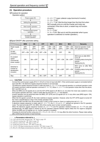
![357
Special operation and frequency control
4
PARAMETERS
4.25.3 Load torque high speed frequency control (Pr. 4, Pr. 5, Pr. 270 to Pr. 274)
<Connection diagram>
Load torque high speed frequency control is a function
which automatically sets the operational maximum
frequency according to the load.
More specifically, the magnitude of the load is judged
according to the average current at a certain time after
starting to perform operation at higher than the preset
frequency under light load.
This function is designed to increase speed
automatically under light load, for example to minimize
the incoming/outgoing time in a multi-story parking lot.
Parameter
Number
Name
Initial
Value
Setting
Range
Description
4
Multi-speed setting (high
speed)
60Hz 0 to 400Hz Set the higher-speed frequency.
5
Multi-speed setting (middle
speed)
30Hz 0 to 400Hz Set the lower-speed frequency.
270
Stop-on contact/load
torque high-speed
frequency control
selection
0
0 Normal operation
1 Stop-on-control (refer to page 205)
2 Load torque high speed frequency control
3
Stop-on-contact (refer to page 205) + load torque high
speed frequency control
271
High-speed setting
maximum current
50% 0 to 220%
Set the upper and lower limits of the current at high and
middle speeds.
272
Middle-speed setting
minimum current
100% 0 to 220%
273 Current averaging range 9999
0 to 400Hz
Average current during acceleration from (Pr. 273 × 1/2)
Hz to (Pr. 273) Hz can be achieved.
9999
Average current during acceleration from (Pr. 5 × 1/2) Hz
to (Pr. 5) Hz is achieved.
274
Current averaging filter
time constant
16 1 to 4000
Set the time constant of the primary delay filter relative to
the output current.
The time constant [ms] is 0.75 × Pr. 274 and the initial
value is 12ms.
A larger setting provides higher stability but poorer response.
<Without high-speed
frequency control>
<With high-speed
frequency control>
Light
Faster
Whether there is a load or
not, the lift is moved
vertically at the same speed.
The lift with a light load or without
a load is moved faster than the lift
with a load.
(The output frequency is increased.)
Mechanical
brake
R/L1
S/L2
T/L3
Motor
MC
STF
CS(X19)*
Start signal
Load torque high-speed frequency
MCCB
Power supply
U
V
W
Pr. 186 = 19
Sink logic
SD
* The used terminal changes according to the Pr. 180 to Pr. 189 (input terminal function selection) settings.](https://image.slidesharecdn.com/fr-a700-instruction-manual-applied-160425021934/85/Catalog-FR-A700-Instruction-manual-applied-Beeteco-com-368-320.jpg)

![359
Special operation and frequency control
4
PARAMETERS
4.25.4 Droop control (Pr. 286 to Pr. 288)
This function is designed to balance the load in proportion to the load torque to provide the speed drooping
characteristic under advanced magnetic flux vector control, real sensorless vector control and vector control.
This function is effective for balancing the load when using multiple inverters
Parameter
Number
Name
Initial
Value
Setting
Range
Description
286 Droop gain 0%
0 Normal operation
0.1% to
100%
Droop control is valid
Set the drooping amount at the rated torque as a
percentage with respect to the rated motor frequency.
287 Droop filter time constant 0.3s 0 to 1s
Set the time constant of the filter applied on the torque
amount current.
288
Droop function activation
selection
0
0
Droop control is not exercised during acceleration/
deceleration.
1
Droop control is always exercised during operation. (with
0 limit)
2
Droop control is always exercised during operation.
(without 0 limit)
10
Droop control is not exercised during acceleration/
deceleration. (Motor speed is referenced)
11
Droop control is always exercised during operation.
(Motor speed is referenced)
(1) Droop control
· The output frequency is changed according to
the magnitude of torque amount current under
advanced magnetic flux vector control, real
sensorless vector control and vector control.
The drooping amount at the rated torque is set
by the droop gain as a percentage using the
rated frequency (Motor speed when Pr. 288 =
"10, 11") as a reference.
· The maximum droop compensation frequency
is 120Hz.
When Pr. 288 = "0 to 2", or under advanced magnetic flux vector control
Droop compensation frequency =
Amount of torque current after filtering
×
Rated motor frequency × Droop gain
Rated value of torque current 100
When Pr. 288 = "10, 11"
Droop compensation frequency =
Amount of torque current after filtering
×
Motor speed × Droop gain
Rated value of torque current 100
REMARKS
Set the droop gain to about the rated slip of the motor.
Magnetic fluxMagnetic fluxMagnetic flux SensorlessSensorlessSensorless VectorVectorVector
Droop compensation
frequency
Ratedfrequency
Torque100%
Droop
gain
-100%
Frequency
0
Rated slip =
Synchronous speed at base frequency - Rated speed
× 100[%]
Synchronous speed at base frequency](https://image.slidesharecdn.com/fr-a700-instruction-manual-applied-160425021934/85/Catalog-FR-A700-Instruction-manual-applied-Beeteco-com-370-320.jpg)

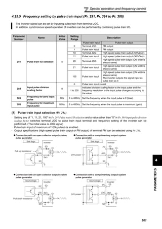


![365
Special operation and frequency control
4
PARAMETERS
(2) Selection of encoder feedback control (Pr. 367 )
(3) Feedback gain (Pr. 368 )
⋅ Set Pr. 368 Feedback gain when the rotation is unstable or response is slow.
⋅ If the acceleration/deceleration time is long, feedback response becomes slower. In this case, increase the Pr. 368
setting.
⋅
(4) Overspeed detection (Pr. 285 )
⋅ If (detection frequency) - (output frequency) > Pr. 285 under encoder feedback control, E.MB1 occurs and the inverter
output is stopped to prevent malfunction when the accurate pulse signal from the encoder can not be detected.
Overspeed is not detected when Pr. 285 = "9999".
⋅ When a value other than "9999" is set in Pr. 367 Speed
feedback range, encoder feedback control is valid.
Using the set point (frequency at which stable speed
operation is performed) as reference, set the higher and
lower setting range. Normally, set the frequency
converted from the slip amount (r/min) of the rated motor
speed (rated load). If the setting is too large, response
becomes slow.
Example: Rated speed of a 4-pole motor is 1740r/min (60Hz)
Slip Nsp = Synchronous speed - Rated speed Frequency equivalent to slip (fsp)
= 1800 - 1740 = 60(r/min)
fsp =
Nsp × Number of poles
=
60 × 4
= 2 (Hz)
120 120
Pr. 368 Setting Description
Pr. 368 > 1 Although the response becomes faster, overcurrent or unstable rotation is liable to occur.
1 < Pr. 368 Although the response becomes slower, the motor rotation becomes stable.
CAUTION
⋅ The encoder should be coupled on the same axis with the motor shaft with a speed ratio of 1 to 1 without any mechanical
looseness.
⋅ During acceleration/deceleration, encoder feedback control is not performed to prevent unstable phenomenon such as hunting.
⋅ Encoder feedback control is performed once output frequency has reached within [set speed] ± [speed feedback range].
⋅ If the following conditions occur during encoder feedback control, the inverter operates at the frequency within [set speed] ±
[speed feedback range] without coming to an alarm stop nor tracking the motor speed.
⋅ The pulse signals are not received from the encoder due to a signal loss, etc.
⋅ The accurate pulse signal from the encoder can not be detected due to induction noise, etc.
⋅ The motor has been forcibly accelerated (regeneration) or decelerated (motor lock or the like) by large external force.
⋅ For the motor with brake, use the RUN signal (inverter running) to open the brake. (The brake may not be opened if the FU
(output frequency detection) signal is used.)
⋅ Do not turn off the external power supply of the encoder during encoder feedback control. Encoder feedback control functions
abnormally.
♦ Parameters referred to ♦
Pr. 81 Number of motor poles Refer to page 144
Speed feedback range
Set value
(Set command)
Driven load Regeneration load](https://image.slidesharecdn.com/fr-a700-instruction-manual-applied-160425021934/85/Catalog-FR-A700-Instruction-manual-applied-Beeteco-com-376-320.jpg)


![368
Useful functions
4.26 Useful functions
4.26.1 Cooling fan operation selection (Pr. 244)
⋅ In either of the following cases, fan operation is regarded as faulty, [FN] is shown on the operation panel, and the fan
fault (FAN) and minor fault (LF) signals are output.
⋅Pr. 244 = "0"
When the fan comes to a stop with power on
⋅Pr. 244 = "1"
When the fan stops during the fan ON command while the inverter is running
⋅ For the terminal used for FAN signal output, set "25" (positive logic) or "125" (negative logic) in any of Pr. 190 to Pr.
196 (output terminal function selection), and for the LF signal, set "98" (positive logic) or "198" (negative logic).
Purpose Parameter that must be Set
Refer to
Page
Increase cooling fan life Cooling fan operation selection Pr. 244 368
To determine the maintenance time
of parts.
Inverter part life display Pr. 255 to Pr. 259 369
Maintenance output function Pr. 503, Pr. 504 372
Current average value monitor
signal
Pr. 555 to Pr. 557 373
Freely available parameter Free parameter Pr. 888, Pr. 889 375
You can control the operation of the cooling fan (FR-A720-1.5K or more, FR-A740-2.2K or more) built in the
inverter.
Parameter
Number
Name Initial Value Setting Range Description
244 Cooling fan operation selection 1
0
A cooling fan operates at power on
Cooling fan on/off control invalid (The
cooling fan is always on at power on)
1
Cooling fan on/off control valid
The fan is always on while the inverter is
running. During a stop, the inverter status
is monitored and the fan switches on-off
according to the temperature.
CAUTION
⋅ When terminal assignment is changed using Pr. 190 to Pr. 196 (output terminal function selection), the other functions may be
affected. Please make setting after confirming the function of each terminal.
♦ Parameters referred to ♦
Pr. 190 to Pr. 196 (output terminal function selection) Refer to page 230](https://image.slidesharecdn.com/fr-a700-instruction-manual-applied-160425021934/85/Catalog-FR-A700-Instruction-manual-applied-Beeteco-com-379-320.jpg)


![378
Setting of the parameter unit and
operation panel
(2) Disable the setting dial and key operation of the operation panel (Press [MODE] long (2s))
⋅ Operation using the setting dial and key of the operation panel can be made invalid to prevent parameter change
and unexpected start and stop.
⋅ Set "10 or 11" in Pr. 161, then press for 2s to make the setting dial and key operation invalid.
⋅ When the setting dial and key operation is made invalid, appears on the operation panel. When the
setting dial and key operation is invalid, appears if the setting dial or key operation is performed. (When
the setting dial or key operation is not performed for 2s, the monitor display appears.)
⋅ To make the setting dial and key operation valid again, press for 2s.
4.27.3 Buzzer control (Pr. 990)
The above parameters allow its setting to be changed during operation in any operation mode even if "0" (initial value) is set in Pr. 77 Parameter write
selection.
4.27.4 PU contrast adjustment (Pr. 991)
The above parameters are displayed as simple mode parameters only when the parameter unit (FR-PU04/FR-PU07) is connected.
REMARKS
⋅ Even if the setting dial and key operation are disabled, the monitor display is valid.
CAUTION
• Release the operation lock to release the PU stop by key operation.
You can make the buzzer "beep" when you press key of the operation panel (FR-DU07) and parameter unit (FR-
PU04/FR-PU07).
Parameter
Number
Name Initial Value Setting Range Description
990 PU buzzer control 1
0 Without buzzer
1 With buzzer
Contrast adjustment of the LCD of the parameter unit (FR-PU04/FR-PU07) can be performed.
Decreasing the setting value makes contrast light.
Parameter
Number
Name Initial Value Setting Range Description
991 PU contrast adjustment 58 0 to 63
0 : Light
↓
63: Dark](https://image.slidesharecdn.com/fr-a700-instruction-manual-applied-160425021934/85/Catalog-FR-A700-Instruction-manual-applied-Beeteco-com-389-320.jpg)


![4
PARAMETERS
383
Check and clear of the alarm history
4.31 Check and clear of the alarm history
(1) Check for the alarm (major fault) history
Alarm history
Monitor/frequency setting
[Operation panel is used
for operation]
Parameter setting
[Parameter setting change]
[Operation for displaying alarm history]
Eight past alarms can be displayed with the setting dial.
(The latest alarm is ended by ".".)
When no alarm exists, is displayed.
Output current
Flickering
Output voltage
Flickering
Flickering
Flickering
Press the
setting
dial.
Press the
setting
dial.
Press the
setting
dial.
Energization time
Alarm history number
(The number of past alarms is displayed.)
Flickering
Output frequency
Flickering Flickering](https://image.slidesharecdn.com/fr-a700-instruction-manual-applied-160425021934/85/Catalog-FR-A700-Instruction-manual-applied-Beeteco-com-394-320.jpg)


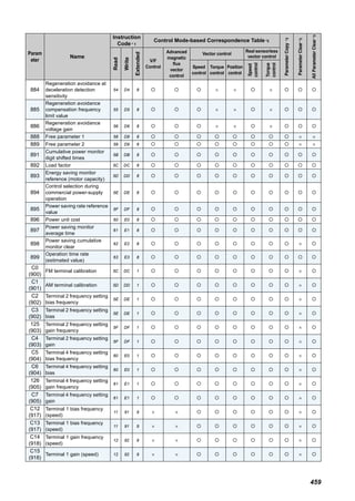


The document is an instruction manual for the Mitsubishi FR-A700 series inverters, detailing safety precautions, installation guidelines, wiring instructions, and operational procedures. It emphasizes the importance of following safety measures to prevent electric shock, fire, and injury, as well as providing specific environmental conditions for optimal operation. The manual also includes technical specifications and parameters for advanced use, along with maintenance and disposal instructions.


