Download to read offline


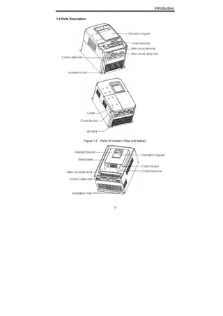


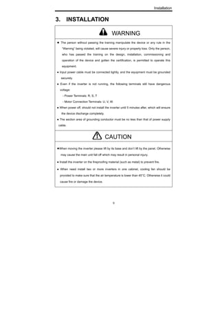


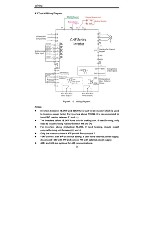


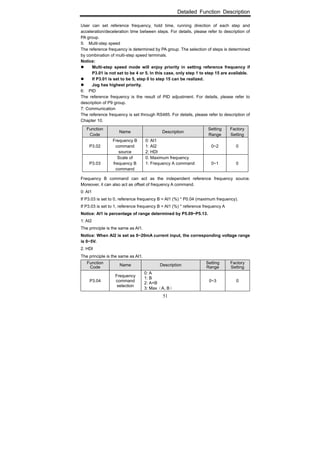
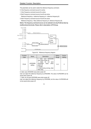


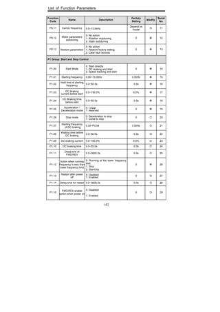

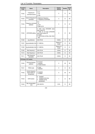


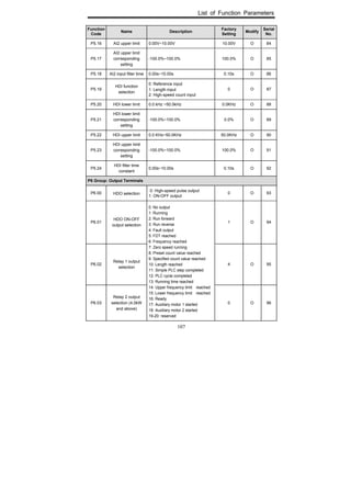
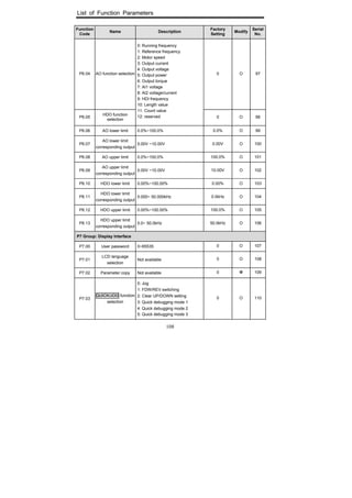


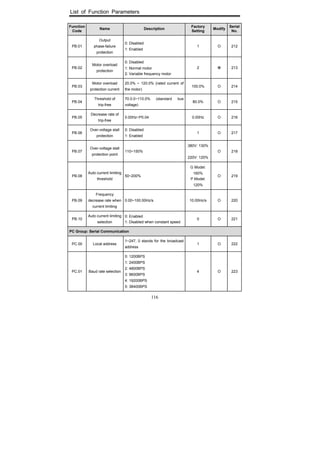

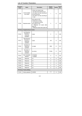

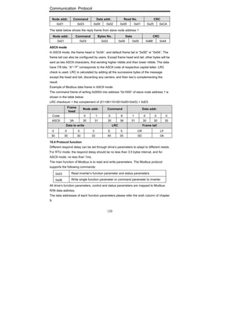
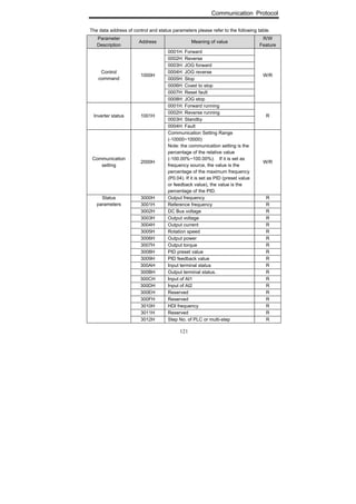


This document is an operation manual for the CHF Series universal inverter. It contains safety precautions and instructions for installation, wiring, operation, function parameters, troubleshooting and maintenance of the inverter. The manual instructs users to read it thoroughly before use to ensure proper usage and safety. It lists the parts and terminals of the inverter and provides typical wiring diagrams. It also describes the keypad functions for controlling and monitoring the inverter. The manual provides detailed settings and applications for the inverter's parameters and functions.


![Ct2000 es manual_english_version_1[1].0](https://cdn.slidesharecdn.com/ss_thumbnails/ct2000esmanualenglishversion11-140613213448-phpapp01-thumbnail.jpg?width=640&height=640&fit=bounds)


![Ct2000 pro plus_manual_english[1]](https://cdn.slidesharecdn.com/ss_thumbnails/ct2000proplusmanualenglish1-140613213527-phpapp02-thumbnail.jpg?width=640&height=640&fit=bounds)


