Download to read offline

![5
Table of Contents
USER SELECTION GUIDE (iH SPECIFICATIONS) ...................................................................... 6
CHAPTER 1 - INSTALLATION..................................................................................................... 9
1.1 Inspection.......................................................................................................................... 9
1.2 Environmental Conditions................................................................................................. 9
1.3 Mounting ........................................................................................................................... 9
1.4 Other Precautions........................................................................................................... 10
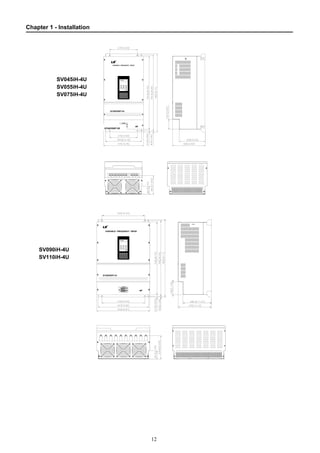
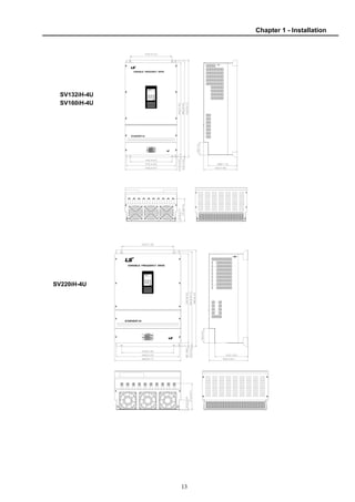
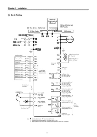
1.5 Dimensions ..................................................................................................................... 11
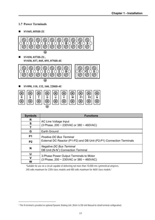
1.6 Basic Wiring.................................................................................................................... 14
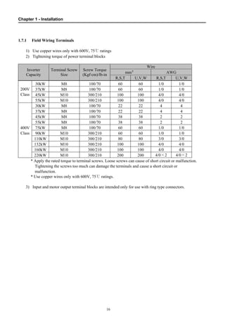
1.7 Power Terminals............................................................................................................. 15
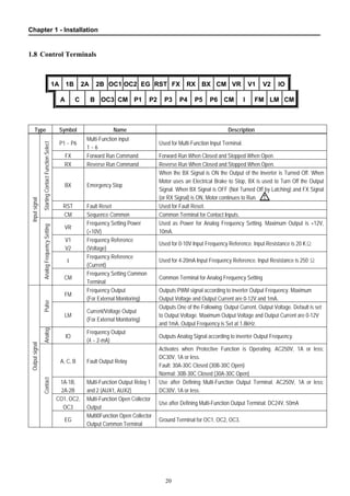
1.8 Control Terminals............................................................................................................ 20
CHAPTER 2 - OPERATION........................................................................................................ 22
2.1 Parameter Groups .......................................................................................................... 22
2.2 Display ............................................................................................................................ 23
2.3 Alpha-numerical Display ................................................................................................. 23
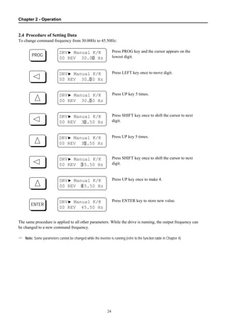
2.4 Procedure of Setting Data............................................................................................... 24
2.5 Parameter Navigation ..................................................................................................... 25
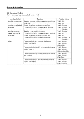
2.6 Operation Method ........................................................................................................... 26
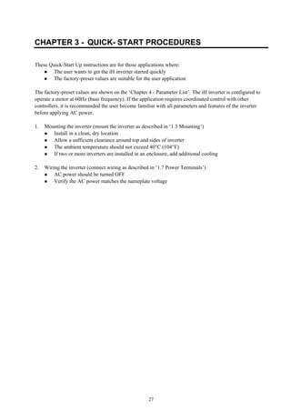
CHAPTER 3 - QUICK- START PROCEDURES ......................................................................... 27
3.1 Operation Using Keypad................................................................................................. 28
3.2 Operation Using Control Terminal – External Start, Stop and Speed Reference ........... 30
3.3 Operation Using Both Keypad and Control Terminals .................................................... 32
CHAPTER 4 - PARAMETER LIST.............................................................................................. 35
4.1 Drive Group..................................................................................................................... 35
4.2 Function Group ............................................................................................................... 35
4.3 I/O Group ........................................................................................................................ 39
CHAPTER 5 - PARAMETER DESCRIPTION............................................................................. 43
5.1 Drive Group [DRV].......................................................................................................... 43
5.2 Function Group ............................................................................................................... 45
5.3 I/O Group ........................................................................................................................ 65
CHAPTER 6 - TROUBLESHOOTING & MAINTENANCE ......................................................... 79
6.1 Fault Display ................................................................................................................... 79
6.2 Fault Remedy.................................................................................................................. 80
6.3 Troubleshooting .............................................................................................................. 81
6.4 How to Check Power Components................................................................................. 86
6.5 Maintenance ................................................................................................................... 87
6.6 Daily and Periodic Inspection Items................................................................................ 88
APPENDIX A - FUNCTIONS BASED ON USE............................................................................ 89
APPENDIX B - PARAMETERS BASED ON APPLICATION....................................................... 90
DECLARATION OF CONFORMITY ............................................................................................. 91](https://image.slidesharecdn.com/sv-ih-140613211445-phpapp01/85/Sv-i-h-6-320.jpg)
![6
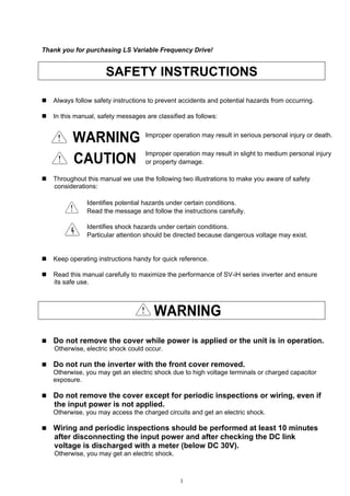
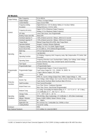
USER SELECTION GUIDE (iH SPECIFICATIONS)
200~230V Class (40 - 75HP)
Model Number SV030iH-2U SV037iH-2U SV045iH-2U SV055iH-2U
Constant Torque [HP] 40 50 60 75Motor
Rating1 Constant Torque [kW] 30 37 45 55
Constant Torque [kVA]2 46 55 68 83Output
Ratings Constant Torque FLA [A] 122 146 180 220
Input Voltage 3 Phase, 200 to 230 V (± 10%)Input
Ratings Input Frequency 50 to 60 Hz (± 5%)
Weight [kg (lbs)] 42 (93) 42 (93) 56 (123) 56 (123)
380~400V Class (40 - 100HP)
Model Number SV030iH-4U SV037iH-4U SV045iH-4U SV055iH-4U SV075iH-4U
Constant Torque [HP] 40 50 60 75 100
Constant Torque [kW] 30 37 45 55 75
Variable Torque [HP] 50 60 75 100 125
Motor
Rating1
Variable Torque [kW] 37 45 55 75 90
Constant Torque FLA [A] 61 75 91 110 152
Constant Torque [kVA]3 40 50 60 70 100
Variable Torque FLA [A] 80 96 115 125 160
Output
Ratings
Variable Torque [kVA] 3 52 62 74 80 103
Input Voltage 3 Phase, 380 to 400 V (± 10%)Input
Ratings Input Frequency 50 to 60 Hz (± 5%)
Weight [kg (lbs)] 45 (99) 45 (99) 63 (139) 63 (139) 68 (150)
380~400V Class (125 - 300HP)
Model Number SV090iH-4U SV110iH-4U SV132iH-4U SV160iH-4U SV220iH-4U
Constant Torque [HP] 125 150 175 215 300
Constant Torque [kW] 90 110 132 160 220
Variable Torque [HP] 150 175 215 250 350
Motor
Rating1
Variable Torque [kW] 110 132 160 185 280
Constant Torque FLA [A] 183 223 264 325 432
Constant Torque [kVA] 3 120 145 170 200 280
Variable Torque FLA [A] 228 264 330 361 477
Output
Ratings
Variable Torque [kVA] 3 147 170 213 233 307
Input Voltage 3 Phase, 380 to 400 V (± 10%)Input
Ratings Input Frequency 50 to 60 Hz (± 5%)
Weight [kg (lbs)] 98 (216) 98 (216) 122 (269) 122 (269) 175 (386)
1 Indicates the maximum applicable capacity when using a 4 Pole motor.
2 Rated kVA (√3*V*I) listed is based on 220VAC operation.
3 Rated kVA (√3*V*I) listed is based on 380VAC operation.](https://image.slidesharecdn.com/sv-ih-140613211445-phpapp01/85/Sv-i-h-7-320.jpg)
![7
440~460V Class (40 - 100HP)
Model Number SV030iH-4U SV037iH-4U SV045iH-4U SV055iH-4U SV075iH-4U
Constant Torque [HP] 40 50 60 75 100
Constant Torque [kW] 30 37 45 55 75
Variable Torque [HP] 50 60 75 100 125
Motor
Rating4
Variable Torque [kW] 37 45 55 75 90
Constant Torque FLA [A] 61 75 91 110 152
Constant Torque [kVA]5 45 56 68 82 113
Variable Torque FLA [A] 80 96 115 125 160
Output
Ratings
Variable Torque [kVA] 5 60 70 86 93 120
Input Voltage 3 Phase, 440 to 460 V (± 10%)Input
Ratings Input Frequency 50 to 60 Hz (± 5%)
Weight [kg (lbs)] 45 (99) 45 (99) 63 (139) 63 (139) 68 (150)
440~460V Class (125 - 300HP)
Model Number SV090iH-4U SV110iH-4U SV132iH-4U SV160iH-4U SV220iH-4U
Constant Torque [HP] 125 150 200 250 300
Constant Torque [kW] 90 110 132 160 220
Variable Torque [HP] 150 200 250 300 350
Motor
Rating4
Variable Torque [kW] 110 132 185 220 280
Constant Torque FLA [A] 183 223 264 325 432
Constant Torque [kVA] 5 136 166 197 242 322
Variable Torque FLA [A] 228 264 330 361 477
Output
Ratings
Variable Torque [kVA] 5 170 200 246 270 356
Input Voltage 3 Phase, 440 to 460 V (± 10%)Input
Ratings Input Frequency 50 to 60 Hz (± 5%)
Weight [kg (lbs)] 98 (216) 98 (216) 122 (269) 122 (269) 175 (386)
4 Indicates the maximum applicable capacity when using a 4 Pole motor.
5 Rated kVA (√3*V*I) listed is based on 440VAC operation.](https://image.slidesharecdn.com/sv-ih-140613211445-phpapp01/85/Sv-i-h-8-320.jpg)
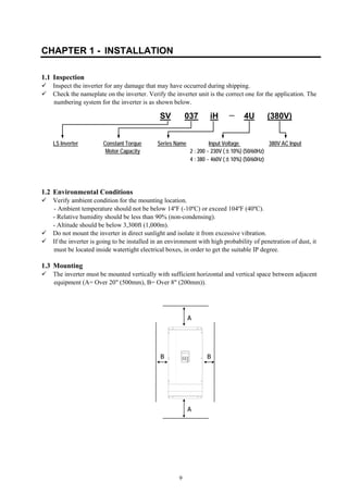
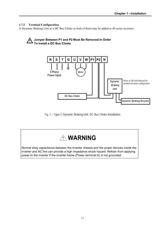
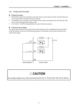
![Chapter 1 - Installation
10
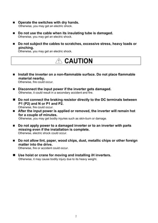
1.4 Other Precautions
Do not carry the inverter by the front cover.
Do not install the inverter in a location where excessive vibration is present. Be cautious when
installing on presses or moving equipment.
The life span of the inverter is greatly affected by the ambient temperature. Install in a location where
temperature are within permissible limits (- 10 ~ 40 ℃).
The inverter operates at high-temperatures - install on a non-combustible surface.
Do not install the inverter in high-temperature or high-humidity locations.
Do not install the inverter in a location where oil mist, combustible gas, or dust is present. Install the
inverter in a clean location or in an enclosed panel, free of foreign substance.
When installing the inverter inside a panel with multiple inverters or a ventilation fan, use caution.
If installed incorrectly, the ambient temperature may exceed specified limits.
Install the inverter using screws or bolts to insure the inverter is firmly fastened.
Inverter
GOOD (O) BAD (X)
Inverter
Cooling fan
Panel Panel
Inverter
Inverter
[When installing several inverters in a panel]
Ventilating fan
GOOD (O) BAD (X)
[When installing a ventilating fan in a panel]](https://image.slidesharecdn.com/sv-ih-140613211445-phpapp01/85/Sv-i-h-11-320.jpg)
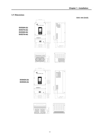
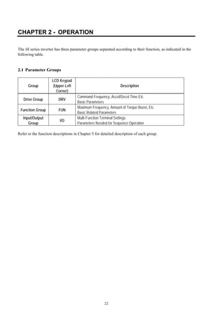
![Chapter 2 - Operation
25
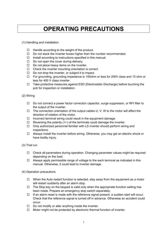
2.5 Parameter Navigation
In any of the parameter groups, users may jump to a specific parameter code by following these steps:
Select a parameter group that requires a change.
At the beginning of each program group the menu will read [Jump Code]. Press the [PROG] key. Enter
the code number of the parameter needing to be changed, then press [ENTER] key. There is no jump
code for [Drive Group].
DRV▶ Manual K/K
00 FWD 60.00 Hz
FUN▶ Jump Code
00 41
I/O▶ Jump Code
00 1
MODE MODE
MODE
DRV▶ Acc. time
01 30.0 sec
DRV▶ Dec. time
02 30.0 sec
DRV▶ Current
03 x.x A
DRV▶ Speed
04 xxxrpm
DRV▶ Power
05 57.5kW
MODE
MODE
MODE
MODE
MODE
FUN▶ Freq. set
01 Key
FUN▶Run/stop set
02 Key
FUN▶Run prohibit
03 None
FUN▶ Freq. max
04 60.00 Hz
FUN▶ Freq. base
05 60.00 Hz
MODE
MODE
MODE
MODE
MODE
I/O▶ P1 input
01 SPD_L
I/O▶ P2 input
02 SPD_M
I/O▶ P3 input
03 SPD_H
I/O▶ P4 input
04 ACCT_L
I/O▶ P5 input
5 ACCT_M
MODE
MODE
MODE
MODE
MODE
FUN▶ Para. lock
98 0
MODE
I/O▶DN: In Inst
65 Instance 70
MODE
MODE
DRV▶ Fault
06 No fault
▼ ▲
▼ ▲
▼ ▲
▼ ▲
▼ ▲
▼ ▲
▼ ▲
▼ ▲
▼ ▲
▼ ▲
▼ ▲
▼ ▲ ▼ ▲
▼ ▲
▼ ▲
▼ ▲
▼ ▲
▼ ▲
Drive Group Function Group I/O Group](https://image.slidesharecdn.com/sv-ih-140613211445-phpapp01/85/Sv-i-h-26-320.jpg)
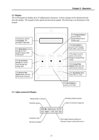
![Chapter 3 – Quick-Start Procedures
28
3.1 Operation Using Keypad
1. Apply AC power.
2. If the message of DRV 00 is ‘Manual K/K’, go to step 11.
3. Press the [PROG] key to display function group.
4. Press the UP-arrow key to display FUN 01.
5. Press the [PROG] key to enter into the program mode.
6. Using arrow keys, select ‘Key”, then press the [ENTER] key.
7. Press UP-arrow key to display FUN 02.
8. Press [PROG] key to enter into the program mode.
9. Using arrow keys, select ‘Key’, then press the [ENTER] key.
10.Press the [MODE] key repeatedly until DRV 00 is displayed.
DRV▶ Manual K/K
00 FWD 0.00 Hz
MODE FUN▶ Jump code
00 41
FUN▶ Freq. set
01 Terminal
PROG FUN▶ Freq. set
01 Terminal
FUN▶ Freq. set
01 Key
FUN▶Run/stop set
02 Terminal-1
PROG
FUN▶Run/stop set
02 Terminal-1
FUN▶Run/stop set
02 Key
ENTER
MODE
ENTER
DRV▶ Manual K/K
00 FWD 0.00 Hz](https://image.slidesharecdn.com/sv-ih-140613211445-phpapp01/85/Sv-i-h-29-320.jpg)
![Chapter 3 – Quick-Start Procedures
29
11.Set the frequency reference by pressing the [PROG] key. Using
arrow keys, change the data to 5.00 Hz. Press the [ENTER] key.
12.Press UP-arrow key to display DRV 01. Change the acceleration
time by pressing the [PROG], arrow and [ENTER] keys.
13.Press the UP-arrow key to display DRV 02. Change the
Deceleration time by pressing the [PROG], arrow and
[ENTER] keys.
14.Press the [FWD] key to run motor in the forward direction.
15.Press the [REV] key to run motor in the reverse direction.
16.Press the [STOP] key to stop motor.
PROG
DRV▶ Manual K/K
00 FWD 0.00 Hz5
DRV▶ Acc. time
01 30.0sec
ENTER
PROG ENTER
DRV▶ Dec. time
02 30.0sec
PROG ENTER
FWD The FWD LED starts blinking.
REV The REV LED starts blinking.
STOP The STOP LED starts blinking.](https://image.slidesharecdn.com/sv-ih-140613211445-phpapp01/85/Sv-i-h-30-320.jpg)
![Chapter 3 – Quick-Start Procedures
30
3.2 Operation Using Control Terminal – External Start, Stop and Speed Reference
1. Confirm ‘Manual T/T’ in DRV 00.
2. If different, as in section 3.1 of this chapter, select
‘Terminal’ in FUN 01 and ‘Terminal-1’ or Terminal-2’
in FUN 02.
3. Install a potentiometer on terminals V1, VR and CM
as shown right below. Select ‘V1’ in FUN 20 to control the
speed by potentiometer alone.
4. Set a frequency reference using the potentiometer.
Make sure to observe the set value in DRV 00.
5. When a ‘4 - 20mA’ current source is used as the
frequency reference, use terminal I and CM.
Select ‘I’ in FUN 20 to control the speed by the
current source alone.
6. To run the motor in the forward direction, close
the [FX] terminal to the [CM] terminal.
7. To run the motor in the reverse direction, close
the [RX] terminal to the [CM] terminal.
DRV▶ Manual T/T
00 FWD 60.00 Hz
FUN▶ Freq. set
01 Terminal
FUN▶Run/stop set
02 Terminal-1
FUN▶ V-I mode
20 V
10 ㏀, 1/2 W
EG RST FX RX
P2 P3 P4 P5
BX CM VR V1
P6 CM I FM
V2 IO
LM CM
FUN▶ V-I mode
20 I
EG RST FX RX
P2 P3 P4 P5
BX CM VR V1
P6 CM I FM
V2 IO
LM CM
4 - 20mA](https://image.slidesharecdn.com/sv-ih-140613211445-phpapp01/85/Sv-i-h-31-320.jpg)
![Chapter 3 – Quick-Start Procedures
31
[FUN 02 - ‘Terminal-1’ Operation] [FUN 02 - ‘Terminal-2’ Operation]
Time
FX-CM
Output Frequency
Time
ON
Time
RX-CM ON
Time
FX-CM
Output Frequency
Time
Time
RX-CM ON
ON](https://image.slidesharecdn.com/sv-ih-140613211445-phpapp01/85/Sv-i-h-32-320.jpg)
![Chapter 3 – Quick-Start Procedures
32
3.3 Operation Using Both Keypad and Control Terminals
3.3.1 Frequency Set by External Source and Run/Stop Set by Keypad
1. Confirm ‘Manual K/T’ in DRV 00.
2. If different, as in section 3.1 of this chapter, select
‘Terminal’ in FUN 01 and ‘Key’ in FUN 02.
3. Install a potentiometer to terminals V1, VR and CM.
Select ‘V1’ in FUN 20 to control the speed by the
potentiometer alone.
4. Set a frequency reference using the potentiometer.
Make sure to observe the set value in DRV 00.
5. When a ‘4 - 20mA’ current source is used as the
frequency reference, use terminals I and CM.
Select ‘I’ in FUN 20 to control the speed by the
current source alone.
6. To run the motor in the forward direction, press
the [FWD] key.
7. To run the motor in the reverse direction, press
the [REV] key.
8. To stop the motor, press the [STOP] key.
DRV▶ Manual K/T
00 FWD 60.00 Hz
FUN▶ Freq. set
01 Terminal
FUN▶Run/stop set
02 Key
FUN▶ V-I mode
20 V1
10 ㏀, 1/2 W
EG RST FX RX
P2 P3 P4 P5
BX CM VR V1
P6 CM I FM
V2 IO
LM CM
FUN▶ V-I mode
20 I
EG RST FX RX
P2 P3 P4 P5
BX CM VR V1
P6 CM I FM
V2 IO
LM CM
4 - 20mA](https://image.slidesharecdn.com/sv-ih-140613211445-phpapp01/85/Sv-i-h-33-320.jpg)
![Chapter 3 – Quick-Start Procedures
33
3.3.2 Frequency Set by Keypad and Run/Stop by External Source
1. Confirm ‘Manual T/K’ in DRV 00.
2. If different, as in section 3.1 of this chapter, select
‘Key’ in FUN 01 and ‘Terminal-1’ or Terminal-2’
in FUN 02.
3. Set a frequency reference in DRV 00.
4. To run the motor in the forward direction, close
the [FX] terminal to the [CM] terminal.
5. To run the motor in the forward direction, close
the [RX] terminal to the [CM] terminal.
DRV▶ Manual T/K
00 FWD 60.00 Hz
FUN▶ Freq. set
01 Key
FUN▶Run/stop set
02 Terminal-1
EG RST FX RX
P2 P3 P4 P5
BX CM VR V1
P6 CM I FM
V2 IO
LM CM
PROG ENTER
DRV▶ Manual T/K
00 FWD 60.00 Hz](https://image.slidesharecdn.com/sv-ih-140613211445-phpapp01/85/Sv-i-h-34-320.jpg)

![35
CHAPTER 4 - PARAMETER LIST
4.1 Drive Group
Code
[DRV]
Description
Drive Group
Keypad Display Setting Range Units
Factory
Default
Adj.
During
Run
Page
00
Output Frequency (During Run) or
Reference Frequency (During Stop)
Cmd. Freq 0 to FUN 04 0.01 0.00 [Hz] Yes 43
01 Acceleration Time Acc. time 0 to 6000 [sec] 0.1 30 [sec] Yes 43
02 Deceleration Time Dec. time 0 to 6000 [sec] 0.1 60 [sec] Yes 43
03 Output Current Current The Load Current in RMS - - [A] - 43
04 Output Speed Speed The Motor Speed in RPM - - [rpm] - 43
05 Output Power Display Power Inverter Output Power - - [kW] - 43
06 Fault Display Fault - - - - 43
4.2 Function Group
Code
[FUN]
Description
Function Group
Keypad Display Setting Range Units
Factory
Default
Adj.
During
Run
Page
00 Jump to Desired Code # Jump Code 1 to 98 1 41 Yes 45
01 Frequency Setting Mode Freq. set
Key,
Terminal,
Remote
- Key No 45
02 Run / Stop Mode Selection Run/stop set
Key,
Terminal-1,
Terminal-2,
Remote
- Key No 45
03 Run Prevention Run prohibit
None,
FWD disable,
REV disable
- None No 46
04
Maximum Frequency Output
Set Point
Freq. max 40 to 400 [Hz] 0.01 60 [Hz] No 46
05 Base Frequency Freq. base 40 to FUN 04 0.01 60 [Hz] No 46
06 Starting Frequency Freq. start 0.5 to 5[Hz] 0.01 0.5 [Hz] No 46
07 Starting Frequency Hold Time Hold time 0 to 10 [sec] 0.1 0.0 [sec] Yes 47
08 Volts / Hz Pattern V/F pattern
Linear,
2.0 (Squared),
User,
Auto
- Linear No 47
09 Torque Boost in Forward Direction Fwd boost 0 to 20 [%] 1 2 [%] No 48
10 Torque Boost in Reverse Direction Rev boost 0 to 20 [%] 1 2 [%] No 48
11 Acceleration Pattern Acc. pattern
Linear,
S-Curve,
U-curve
- Linear No 49
12 Deceleration Pattern Dec. pattern
Linear,
S-Curve,
U-Curve
- Linear No 49
13 Output Voltage Adjustment Volt control 40 to 110 [%] 1 100 [%] No 49](https://image.slidesharecdn.com/sv-ih-140613211445-phpapp01/85/Sv-i-h-36-320.jpg)
![Chapter 4 - Parameter List
36
Code
[FUN]
Description
Function Group
Keypad Display Setting Range Units
Factory
Default
Adj.
During
Run
Page
14 Energy Savings Level Energy save 70 to 100 [%] 1 100 [%] Yes 50
15 Stop Mode Selection Stop mode
Decel,
DCBR,
Free Run
- Decel No 50
16 User V/F - Frequency 1 User-1f 0 to 30 [Hz] 0.01 10.00 [Hz] No 51
17 User V/F - Voltage 1 User-1v 0 to 50 [%] 1 15 [%] No 51
18 User V/F - Frequency 2 User-2f
FUN 16 to
FUN 04
1 30.00 [Hz] No 51
19 User V/F - Voltage 2 User-2v FUN 17 to 100 [%] 1 50 [%] No 51
20 Analog Speed Input Selection V-I mode
V1,
I,
V1 + I,
V2
- V1 No 51
21 Analog Speed Input Filter Gain Filter gain 1 to 100 [%] 1 25 [%] Yes 52
22 Analog Speed Input Gain Analog gain 50 to 250 [%] 0.1 100.0 [%] Yes 52
23 Analog Speed Input Bias Analog bias 0 to 200 [%] 0.1 100.0 [%] Yes 52
24 Analog Speed Input Direction Analog dir
Direct,
Invert
- Direct Yes 52
25 Frequency Limit Selection Freq. limit
No,
Yes
- No No 54
26 Frequency High Limit Selection F-limit high 0 to FUN 04 0.01 60.00 [Hz] No 54
27 Frequency Low Limit Selection F-limit low 0 to FUN 26 0.01 0.00 [Hz] No 54
28 Jump Frequency Selection Freq. jump
No,
Yes
- No No 54
29 Jump Frequency 1 Freq-jump 1f 0 to FUN 04 0.01 10.00 [Hz] No 54
30 Jump Frequency 2 Freq-jump 2f 0 to FUN 04 0.01 20.00 [Hz] No 54
31 Jump Frequency 3 Freq-jump 3f 0 to FUN 04 0.01 30.00 [Hz] No 54
32 Jump Frequency Bandwidth Freq. band 0 to 30 [Hz] 0.01 5.00 [Hz] No 54
33 DC Injection Braking Frequency DC-br freq 0 to 60 [Hz] 0.01 0.50 [Hz] No 55
34
DC Injection Braking On-Delay
Time
DC-br block 0.5 to 5 [sec] 0.1 2 [sec] No 55
35 DC Injection Braking Time DC-br time 0.1 to 25 [sec] 0.1 0.5 [sec] No 55
36 DC Injection Braking Voltage DC-br value 1 to 20 [%] 1 1 [%] No 55
37 Slip Compensation Slip compen.
No,
Yes
- No No 56
38 Rated Motor Slip Rated slip 0 to 5 [Hz] 0.01 0.00 [Hz] No 56
39 Rated Motor Current (RMS) M-rated cur. 0.1 to 999 [A] 0.1 103.0 [A]1 No 56
40 No Load Motor Current in RMS No-load cur. 0.1 to 300 [A] 0.1 0.1 [A] No 56
41 Inverter Capacity Inv Capacity
SV030iH-2U
SV037iH-2U
···
···
SV315iH-4U
- SV030iH-22 No 56
1 Default value will depend on the inverter capacity.
2 FUN 41 is set at its inverter capacity before shipping outside. However, inverter loses its capacity after parameter initialization in FUN 97. If the
parameters are initialized, be sure to re-set the inverter capacity to the right capacity.](https://image.slidesharecdn.com/sv-ih-140613211445-phpapp01/85/Sv-i-h-37-320.jpg)
![Chapter 4 - Parameter List
37
Code
[FUN]
Description
Function Group
Keypad Display Setting Range Units
Factory
Default
Adj.
During
Run
Page
SV375iH-4U
42 Number of Auto Restart attempt Retry number 0 to 10 1 0 Yes 56
43 Delay Time Before Auto Restart Retry time 0 to 10 [sec] 1 1 [sec] Yes 56
44 Fault Output Relay (A, C, B) Relay mode
Retry 0,
All Trips,
LV + Retry 0,
LV + All Trips
- Retry 0 Yes 57
45 Stall Prevention Mode Stall mode
None,
Acc,
Steady,
Acc + Steady,
Dec,
Acc + Dec,
Dec + Steady,
Acc + Dec+
Steady
- None Yes 57
CT: 30 to 150 [%] 1 150 [%] Yes
46 Stall Prevention Level Stall level
VT: 30 to 110 [%] 1 110 [%] Yes
57
CT: 30 to 150 [%] 1 150 [%] Yes
47 Overload Warning Level OL level
VT: 30 to 110 [%] 1 110 [%] Yes
58
48 Overload Warning Hold Time OL time 1 to 30 [sec] 1 10 [sec] Yes 58
CT: 30 to 200 [sec] 1 160 [%] Yes
49 Over Current Trip Limit Level OC lim level
VT: 30 to 150 [sec] 1 110 [%] Yes
59
50 Over Current Limit Time OC lim. Time 0 to 60 [sec] 0.1 60 [sec] Yes 59
51 Electronic Thermal Selection ETH select No, Yes - No Yes 59
52 Electronic Thermal Level ETH level 110 to 150 [%] 1 150 [%] Yes 59
53
Electronic Thermal Characteristic
(Motor Type) Selection
Motor type
General,
Special
- General Yes 59
54 Number of Motor Poles Pole number 2 to 12 1 4 Yes 60
55
IPF (Instant Power Failure)
Restart Selection
IPF select
No,
Yes
- No Yes 61
56 Speed Search Acceleration Time SS acc. time 0.1 to 600 [sec] 0.1 5 [sec] Yes 61
57 Speed Search Deceleration Time SS dec. Time 0.1 to 600 [sec] 0.1 10 [sec] Yes 61
58 Speed Search Gain SS gain 0 to 200 [%] 1 100 [%] Yes 61
59 Restart after Fault Reset Selection RST-restart
No,
Yes
- No Yes 61
60 Restart after Power-On Selection Power on st
No,
Yes
- No Yes 62
61 Carrier Frequency Carrier Freq 2 to 10 [kHz] 1 6 [kHz]3 No 62
3 Carrier Frequency according to the Inverter Capacity (The Carrier Frequency is set to 3kHz for VT Rating)
Inverter Setting
Range
Factory
Default
Inverter Setting
Range
Factory
Default
SV030iH-2U 2 to 10 6kHz SV075iH-4U 2 to 7 6kHz
SV037iH-2U 2 to 10 6kHz SV090iH-4U 2 to 6 6kHz
SV045iH-2U 2 to 8 6kHz SV110iH-4U 2 to 6 6kHz](https://image.slidesharecdn.com/sv-ih-140613211445-phpapp01/85/Sv-i-h-38-320.jpg)
![Chapter 4 - Parameter List
38
Code
[FUN]
Description
Function Group
Keypad Display Setting Range Units
Factory
Default
Adj.
During
Run
Page
62 PI Control Selection PI-control
No,
Yes
- No No 63
63 PI Proportional Gain P-gain 1 to 30000 1 10 Yes 63
64 PI Integral Gain I-gain 1 to 30000 1 50 Yes 63
65 PI Feedback Selection PI-fb select I, V1, V2 - I No 63
66 PI Feedback Filter Gain PI-fb filt. G 1 to 100 [%] 1 25 [%] Yes 63
67 PI Feedback Gain PI-fb gain 50 to 250 [%] 0.1 100.0 [%] Yes 63
68 PI Feedback Bias PI-fb bias 0 to 200 [%] 0.1 100.0 [%] Yes 63
69 PI Feedback Direction PI-fb dir
Direct,
Invert
- Direct No 63
70 PI I Gain Scale I_term scale 1 to 100 [%] 1 100 [%] Yes 63
71 PI Controller Error Direction PI error dir
Direct,
Invert
- Direct No 63
72 PI Control Bypass Regul bypass No, Yes - No No 63
944 CT/VT Selection CT/VT
Constant Trq,
Variable Trq
-
Constant
Trq
No 64
95
Read Parameters into Keypad
from Drive
Para. Read
No,
Yes
- No No 64
96
Write Parameters to Drive
from Keypad
Para. Write
No,
Yes
- No No 64
97
Initialize Parameters to Factory
Default Settings
Para. Init
No,
Yes
- No No 64
98 Parameter Write Protection Para. Lock 0 to 255 1 0 Yes 64
SV055iH-2U 2 to 8 6kHz SV132iH-4U 2 to 5 5kHz
SV030iH-4U 2 to 10 6kHz SV160iH-4U 2 to 4 4kHz
SV037iH-4U 2 to 10 6kHz SV220iH-4U 2 to 4 4kHz
SV045iH-4U 2 to 8 6kHz SV315iH-4U 2 to 4 4kHz
SV055iH-4U 2 to 8 6kHz SV375iH-4U 2 to 4 4kHz
4 VT is available only for 400V class inverter.](https://image.slidesharecdn.com/sv-ih-140613211445-phpapp01/85/Sv-i-h-39-320.jpg)
![Chapter 4 - Parameter List
39
4.3 I/O Group
Code
[I/O]
Description
Function Group
Keypad Display Setting Range Units
Factory
Default
Adj.
During
Run
Page
00 Jump to Desired Code # Jump Code 1 to 65 1 1 Yes 65
01 Multi-function Input 1 (P1 terminal) P1 Input - SPD_L No 65
02 Multi-function Input 2 (P2 terminal) P2 Input - SPD_M No 65
03 Multi-function Input 3 (P3 terminal) P3 Input - SPD_H No 65
04 Multi-function Input 4 (P4 terminal) P4 Input - ACCT_L No 65
05 Multi-function Input 5 (P5 terminal) P5 Input - ACCT_M No 65
06 Multi-function Input 6 (P6 terminal) P6 Input
SPD_L,
SPD_M,
SPD_H,
JOG,
ACCT_L,
ACCT_M,
ACCT_H,
UP,
DOWN,
HOLD,
DIS_OPT,
COMM_CONN,
EXT_DCBR,
EXT_TRIP - ACCT_H No 65
07 Multi-function Output 1 (OC1 terminal) OC1 Output - STEP_L No 68
08 Multi-function Output 2 (OC2 terminal) OC2 Output - STEP_M No 68
09 Multi-function Output 3 (OC3 terminal) OC3 Output - STEP_H No 68
10
Multi-function Output 4
(Aux.1 Relay term.)
AUX1 output - COMM No 68
11
Multi-function Output 5
(Aux. 2 Relay term.)
AUX2 output
FST_LO,
FST_HI,
FDT_HI,
FDT_PULSE,
FDT_BAND,
OL,
STALL,
LV,
RUN,
COMM,
STEP_L,
STEP_M,
STEP_H
- COMM No 68
12 Jog Frequency Jog freq. 0 to FUN 04 0.01 30.00 [Hz] Yes 72
13 Step Speed 1 Step freq-1 0 to FUN 04 0.01 10.00 [Hz] Yes 72
14 Step Speed 2 Step freq-2 0 to FUN 04 0.01 20.00 [Hz] Yes 72
15 Step Speed 3 Step freq-3 0 to FUN 04 0.01 30.00 [Hz] Yes 72
16 Step Speed 4 Step freq-4 0 to FUN 04 0.01 40.00 [Hz] Yes 72
17 Step Speed 5 Step freq-5 0 to FUN 04 0.01 50.00 [Hz] Yes 72
18 Step Speed 6 Step freq-6 0 to FUN 04 0.01 46.00 [Hz] Yes 72
19 Step Speed 7 Step freq-7 0 to FUN 04 0.01 37.00 [Hz] Yes 72
20 Acceleration Time 1 Acc time-1 0 to 6000 [sec] 0.1 1.0 [sec] Yes 72
21 Deceleration Time 1 Dec time-1 0 to 6000 [sec] 0.1 1.0 [sec] Yes 72
22 Acceleration Time 2 Acc time-2 0 to 6000 [sec] 0.1 2.0 [sec] Yes 72
23 Deceleration Time 2 Dec time-2 0 to 6000 [sec] 0.1 2.0 [sec] Yes 72
24 Acceleration Time 3 Acc time-3 0 to 6000 [sec] 0.1 3.0 [sec] Yes 72
25 Deceleration Time 3 Dec time-3 0 to 6000 [sec] 0.1 3.0 [sec] Yes 72
26 Acceleration Time 4 Acc time-4 0 to 6000 [sec] 0.1 4.0 [sec] Yes 72
27 Deceleration Time 4 Dec time-4 0 to 6000 [sec] 0.1 4.0 [sec] Yes 72](https://image.slidesharecdn.com/sv-ih-140613211445-phpapp01/85/Sv-i-h-40-320.jpg)
![Chapter 4 - Parameter List
40
Code
[I/O]
Description
Function Group
Keypad Display Setting Range Units
Factory
Default
Adj.
During
Run
Page
28 Acceleration Time 5 Acc time-5 0 to 6000 [sec] 0.1 5.0 [sec] Yes 72
29 Deceleration Time 5 Dec time-5 0 to 6000 [sec] 0.1 5.0 [sec] Yes 72
30 Acceleration Time 6 Acc time-6 0 to 6000 [sec] 0.1 6.0 [sec] Yes 72
31 Deceleration Time 6 Dec time-6 0 to 6000 [sec] 0.1 6.0 [sec] Yes 72
32 Acceleration Time 7 Acc time-7 0 to 6000 [sec] 0.1 7.0 [sec] Yes 72
33 Deceleration Time 7 Dec time-7 0 to 6000 [sec] 0.1 7.0 [sec] Yes 72
34
Output Voltage / Current Meter
(LM Meter) Selection
LM meter
Voltage,
Current
- Voltage Yes 72
35
Output Voltage / Current Meter
(LM Meter) Adjustment (15V Pulse)
LM adj. 0 to 120 [%] 1 100 [%] Yes 72
36
FM Meter Output Adjustment
(15V Pulse)
FM adj. 0 to 120 [%] 1 100 [%] Yes 73
37
IO Meter Output Adjustment
(4 to 20mA)
IO adj. 0 to 120 [%] 1 100 [%] Yes 73
38 Frequency Steady Level FST-freq. 0 to FUN 04 0.01 0.50 [Hz] No 73
39 Frequency Detection Level FDT-freq. 0 to FUN 04 0.01 60.00 [Hz] No 73
40 Frequency Detection Bandwidth FDT-band 0 to 30 [Hz] 0.01 1.00 [Hz] No 73
41
Multiplier Constant for Speed
Display in ‘DRV 04’
Mul. Factor 0 to 999 1 100 Yes 74
42
Divider Constant for Speed
Display in ‘DRV 04’
Div. factor 1 to 999 1 100 Yes 74
43 Status of Input Terminals Ter. Input - - - - 74
44 Status of Output Terminals Ter. Output - - - - 74
45 Software Version S/W version - - 2.xx - 74
46 Fault History 1 Last fault 1 - - Yes 74
47 Fault History 2 Last fault 2
Fault Status,
Freq. at Fault
Current at Fault - - Yes 74
48 Option 1 Selection Option 1
None , RS485,
ModBus RTU,
Fnet,
Device Net
- None No 75
49 Option 2 Selection Option 2 None, MMC - None No 75
505 Inverter number for Option Inv. Number 1 to 31 1 1 Yes 75
51 Baud rate for Option Baud-rate
1200,
2400,
4800,
9600,
19200
- 9600 BPS Yes 75
52 Communication Timeout Comm. Timeout 0 to 60 [sec] 0.1 10.0 [sec] Yes 75
53 PG Slip Frequency for PG Option PG Slip Freq 0 to 10 [Hz] 0.01 5.00 [Hz] No 76
54 PG-P Gain for PG Option PG. P-Gain 0 to 225 1 1 Yes 76
55 PG-I Gain for PG Option PG. I-Gain 0 to 225 1 1 Yes 76
56 PG-Filter Gain for PG Option PG. F-Gain 0 to 225 1 100 Yes 76
57 Encoder Selection for PG Option Enc pulse 100, - 512 Pulse Yes 76
5 Option related parameters (FUN 50 ~ FUN 61) - Please refer to specific option manual.](https://image.slidesharecdn.com/sv-ih-140613211445-phpapp01/85/Sv-i-h-41-320.jpg)
![Chapter 4 - Parameter List
41
Code
[I/O]
Description
Function Group
Keypad Display Setting Range Units
Factory
Default
Adj.
During
Run
Page
500,
512,
1000,
1024,
2000,
2048,
4000
58 Digital Input for DI/DA Option DI Mode
None,
Freq. 1,
Freq. 2
- Freq.1 Yes 76
59 Analog Output for DI/DA Option DA Mode
Freq.,
Voltage,
Current
- Freq. Yes 76
60 Analog Output Adjustment DA adj. 80 to 120 [%] 1 100 [%] Yes 76
61 Inverter Number for FNet FN: St.ID 1 to 63 1 1 No 77
62 Device Net ID DN: MAC ID 0 to 63 1 0 Yes 77
63 Device Net Communication Speed DN: Baud Rate
125 kBPS
250 kBPS
500 kBPS
- 125 kBPS Yes
77
64 Device Net Output Instance DN: Out Inst
20
21
100
101
- 20 No
77
65 Device Net Input Instance DN: In Inst
70
71
110
111
- 70 No
77](https://image.slidesharecdn.com/sv-ih-140613211445-phpapp01/85/Sv-i-h-42-320.jpg)

![43
CHAPTER 5 - PARAMETER DESCRIPTION
5.1 Drive Group [DRV]
DRV 00: Output Frequency / Reference
Frequency
DRV▶ Manual K/K
00 FWD 60.00 Hz
Setting Range: 0 to FUN 04 [Freq. max]
Factory Default: 0.00 Hz
When the inverter is stopped, the LCD display will
read “Reference Frequency”. This is the Target Set
Frequency. While the inverter is running, the LCD
display will read “Output Frequency”.
The Output Frequency may be controlled by the
digital Keypad or analog input (Speed pot) or (4 ~
20mA). The factory default is [Keypad] mode. To
change the output frequency from Keypad to
Terminal, go to [FUN 01].
DRV 01: Acceleration Time
DRV 02: Deceleration Time
DRV▶ Acc. Time
01 30.0 sec
DRV▶ Dec. Time
02 60.0 sec
Setting Range: 0 to 6000 sec
Factory Default: 5.0 sec
The inverter targets [FUN 04] when accelerating or
decelerating. When [FUN 04] is set to ‘Maximum
Frequency’, the acceleration time is the time taken
by the motor to reach [FUN 04] from 0 Hz. The
deceleration time is the time taken by the motor to
reach 0 Hz from [FUN 04] (Maximum Frequency).
The acceleration and deceleration time can be
changed to a preset transient time via multi-
function inputs. By setting the multi-function
inputs (P1~P6) to ‘ACCT_L’, ACCT_M’,
‘ACCT_H’ respectively, the Accel and Decel time
set in [I/O 01] to [I/O 06] are supplied according to
preset speeds assigned in [I/O 20] to [I/O 33].
[Accel/Decel Operation]
DRV 03: Output Current
DRV▶ Current
03 10.0 A
Displays RMS value of the output current when the
drive is running.
DRV 04: Output Speed
DRV▶ Speed
04 1800 rpm
Displays the speed of the motor in RPM. Line
speed of the motor (m/min.) can be calculated by
the number of motor poles [FUN 54] and the
“Multiplier and Divider Factor” [I/O 41], [I/O 42].
Output Frequency
Max. Freq.
Time
Acc. time Dec. time](https://image.slidesharecdn.com/sv-ih-140613211445-phpapp01/85/Sv-i-h-44-320.jpg)
![Chapter 5 - Parameter Description (Drive Group)
44
DRV 05: Output Power Display
DRV▶ Power
05 47.8kW
Displays inverter output power (kW) when the
drive is running.
DRV 06: Fault Display
DRV▶ Fault
05 No Fault
Displays the status of a fault. The output of the
inverter is turned off when a fault condition occurs.
The condition at the time of the fault can be
examined (Motor Current and Output Frequency).
The Stop LED blinks when a fault has occurred.
The following table shows the fault item.
Display Fault Remark
OC Trip Over Current Latch
OV Trip Over Voltage Latch
EXT Trip External Trip Latch
BX Inverter Disable Unlatch
LV Trip Low Voltage Unlatch
Fuse Open Fuse Blown Latch
GF Trip Ground Fault Latch
Over Heat Cooling Problem Latch
ETH Electronic Thermal Protected Latch
OC Limit Over Current Latch
M/C Fail Magnetic Contactor Problem Unlatch
Inv OLT Inverter Overload Latch
SC Trip1 Short Through Trip Latch
Note: A latched fault must be released by the [RESET]
key or reset (RST) terminal. Unlatched faults are released
upon condition or command.
1 Available for models over 220kW. To reset this fault, the main input
power should be disconnected.](https://image.slidesharecdn.com/sv-ih-140613211445-phpapp01/85/Sv-i-h-45-320.jpg)
![Chapter 5 - Parameter Description (Function Group)
45
5.2 Function Group
FUN 00: Jump to Desired Code #
FUN▶ Jump Code
00 41
Setting Range: 0 to 98
Factory Default: 41
Any program code may be jumped to directly by
entering the desired program code number.
Press the [PROG] key, scroll with the [▲ ▼] keys
to the desired program code, the press the
[ENTER] key to move to a desired program code.
FUN 01: Frequency Setting Mode
FUN▶ Freq. set
01 Key
Setting Range: Key, Terminal, Remote
Factory Default: Key
Key: The target frequency is controlled and
established using the Keypad in [DRV 00].
Terminal: The target frequency is controlled and
established using the Terminal with an analog
speed pot (10V DC) or a (4 ~ 20mA) current signal.
Remote: The target frequency is controlled and
established using Option Board.
Note: Analog input may be fine tuned when controlling the
target frequency through the Terminal. (See FUN 20~22)
FUN 02: Run/Stop Mode Selection
FUN▶Run/stop set
02 Key
Setting Range: Key, Terminal-1, Terminal-2, Remote
Factory Default: Key
This function selects Keypad, Terminal-1,
Terminal-2 or Remote (Option Board) as the
source for the Run/Stop command.
Key: Run/Stop is controlled by Keypad.
Terminal-1: Control terminals FX, RX and CM
control Run/Stop.
FX-CM: Forward Run and Stop Control
RX-CM: Reverse Run and Stop Control
Terminal-2: Control terminals FX, RX and CM
control Run/Stop.
FX-CM: Run/Stop control.
RX-CM: Forward and Reverse Control (Toggle)
Remote: Communication Option controls Run/stop.
[Run/Stop: Terminal-1 Operation]
Output frequency
FX-CM
Time
ON
RX-CM ON
Forward
Reverse](https://image.slidesharecdn.com/sv-ih-140613211445-phpapp01/85/Sv-i-h-46-320.jpg)
![Chapter 5 - Parameter Description (Function Group)
46
[Run/Stop: Terminal-2 Operation]
FUN 03: Run Prevention
FUN▶Run prohibit
03 None
Setting Range: None, FWD disable, REV disable
Factory Default: None
This function prevents reverse operation of the
motor. This function may be used for loads that
rotate only in one direction such as fans and pumps.
Setting Range Description
None Forward and Reverse run is available.
FWD disable Forward run is prevented.
REV disable Reverse run is prevented.
FUN 04: Maximum Frequency Set Point
FUN▶ Freq. max
04 60.00 Hz
Setting Range: 40 ~ 400 Hz
Factory Default: 60.00 Hz
This function selects the maximum frequency
output of the inverter. Caution should be exercised
when increasing the motor’s command speed
beyond its nameplate RPM. Please check with the
motor manufacturer before exceeding the base
speed of the motor.
FUN 05: Base Frequency Set Point
FUN▶ Freq. base
05 60.00 Hz
Setting Range: 40 to FUN 04 [Freq. max]
Factory Default: 60.00 Hz
This function selects the output frequency of the
inverter when operating at rated output voltage.
Base frequency cannot be set above the maximum
frequency. [FUN 04] establishes the frequency for
maximum output voltage. This parameter is
normally set to 60Hz. This allows constant torque
operation of the motor up to its base speed. If base
frequency is set to 60Hz and maximum frequency
is set to 120Hz, the motor will run in the constant
torque range up to the motor’s base frequency, and
in the constant horse power range from the motor’s
base frequency to twice the motor’s base frequency.
FUN 06: Start Frequency Set Point
FUN▶ Freq. start
06 0.50 Hz
Setting Range: 0.5 to 5Hz
Factory Default: 0.50 Hz
This function selects the start frequency when the
inverter starts to output voltage.
Output frequency
FX-CM
Time
ON
RX-CM ON
Forward
Reverse](https://image.slidesharecdn.com/sv-ih-140613211445-phpapp01/85/Sv-i-h-47-320.jpg)
![Chapter 5 - Parameter Description (Function Group)
47
Note: If maximum frequency is decrease, all frequency
parameters are adjusted to the maximum frequency set
point.
FUN 07: Hold Time
FUN▶ Hold time
07 0.0sec
Setting Range: 0 to 10 sec
Factory Default: 0.0 sec
This function selects the amount of time to hold the
starting frequency before accelerating.
FUN 08: Volts/Hz Pattern
FUN▶ V/F pattern
08 Linear
Setting Range: Linear, 2.0, User, Auto
Factory Default: Linear
This is the pattern of voltage/frequency ratio.
Select the proper V/F pattern according to the load.
The motor torque is dependent on this V/F pattern.
[Linear] pattern is used where constant torque is
required. It maintains a linear volts/hertz ratio from
zero to base frequency. This pattern is appropriate
for conveyer, parking facility etc.
[2.0] pattern is used where variable torque is
required. It maintains squared and cube powered
ratio characteristics for the volts/hertz ratio. This
pattern is appropriate for fans, pumps etc.
[User] pattern is used for special applications.
Users can adjust the volts/hertz ratio according to
the application. This is accomplished by setting the
voltage and frequency, respectively, at two (2)
points between starting frequency and base
frequency. The two (2) points of voltage and
frequency are set in [FUN 16] through [FUN 19].
Output voltage
Rated
Voltage
Output
Frequency
FUN 06 FUN 05
FUN 04
Output Frequency
Time
Hold Time
FUN 06
Output Voltage
Output
Frequency
Freq. Base
100%
Output Voltage
Output
Frequency
Freq. Base
100%](https://image.slidesharecdn.com/sv-ih-140613211445-phpapp01/85/Sv-i-h-48-320.jpg)
![Chapter 5 - Parameter Description (Function Group)
48
[Auto Boost] pattern is used where high starting
torque is applications. This pattern will
automatically boost the torque by sensing load
current. It has a high torque characteristic at low
speed. [Auto] pattern cannot be used when
operating several motors with one inverter.
FUN 09: Manual Torque Boost – Forward
FUN 10: Manual Torque Boost - Reverse
FUN▶ Fwd boost
09 2 %
Setting Range: 0 to 20 %
Factory Default: 2 %
FUN▶ Fwd boost
10 2 %
Setting Range: 0 to 20 %
Factory Default: 2 %
[FUN 09] and [FUN 10] establish the level of
torque boost in the Forward and Reverse direction.
These functions are used to increase the output
voltage to the motor at low speeds for a higher V/F
ratio loads that require higher than normal starting
torque.
Note: If the torque boost is set higher than needed, it is
possible to over-flux or saturate the motor. This can result
in the motor overheating.
Note: The manual torque boost value can be added to
“Linear” or “2.0” V/F pattern, but not to “User” or “Auto
Boost” V/F pattern.
[Linear V/F Pattern: ‘Torque Boost’]
[2.0 V/F Pattern: ‘Torque Boost’]
[Auto Boost Pattern: ‘Torque Boost’]
Output Voltage
Output
Frequency
Freq. Base
100%
User-2v
User-1v
User-1f
User-2f
Output Voltage
Output
Frequency
Freq. Base
100%
Manual
boost
value
Output Voltage
Output
Frequency
Freq. Base
100%
Manual
boost
value
Output Voltage
Output
Frequency
Freq. Base
100%
Manual
boost value
Auto
boost value
Output Voltage
Output
Frequency
Freq. base
100%
Manual
Boost value
Auto
Boost value
Auto Boost
FUN 08 [V/F Pattern]
Manual Boost FUN 09, FUN 10](https://image.slidesharecdn.com/sv-ih-140613211445-phpapp01/85/Sv-i-h-49-320.jpg)
![Chapter 5 - Parameter Description (Function Group)
49
FUN 11: Acceleration pattern
FUN 12: Deceleration pattern
FUN▶Acc. pattern
11 Linear
FUN▶Dec. pattern
12 Linear
Setting Range: Linear, S-Curve, U-Curve
Factory Default: Linear
[FUN 11] and [FUN 12] selects different
combinations of acceleration and deceleration
patterns.
Linear: This is the general acceleration and
deceleration pattern for constant torque
applications.
[Acc./Dec. Pattern: ‘Linear’]
S-Curve: This pattern allows the motor to
accelerate and decelerat smoothly. At this time, the
actual acceleration and deceleration time are longer
about 10% than the acceleration and deceleration
time set in DRV 01-02.
[Acc./Dec. Pattern: ‘S-Curve’]
U-Curve: This pattern provides more efficient
control of acceleration and deceleration in the
application like winding machines.
[Acc./Dec. Pattern: ‘U-Curve’]
FUN 13: Output Voltage Adjustment
FUN▶Volt control
13 100 %
Setting Range: 40 to 110%
Factory Default: 100%
This function is used to adjust the output voltage of
the inverter. This is useful when using a motor with
a lower rated voltage than the main input voltage.
When this is set at 100%, the inverter outputs its
rated voltage.
[Output Voltage Adjustment]
Output Frequency
Time
Acc. Pattern Dec. Pattern
Output Frequency
Time
Acc. Pattern Dec. Pattern
Output Frequency
Time
Acc. Pattern Dec. Pattern
Output Voltage
Output
Frequency
Freq. Base
100%
50%
When set at 50%](https://image.slidesharecdn.com/sv-ih-140613211445-phpapp01/85/Sv-i-h-50-320.jpg)
![Chapter 5 - Parameter Description (Function Group)
50
FUN 14: Energy Savings Level
FUN▶ Energy save
14 100 %
Setting Range: 70 to 100%
Factory Default: 100%
This function is used to reduce the output voltage
in applications that do not require high torque and
current at its steady speed. The inverter reduces its
output voltage after accelerating to the reference
frequency (steady speed) if the energy save level is
set at 80%. This function may cause over-current
trip due to the lack of output torque in a fluctuating
load.
This function does not work with a 100% set point
value.
[When Energy Save Level is set at 80%]
FUN 15: Stop Mode Selection
FUN▶ Stop mode
15 Decel
Setting Range: Decel, DCBR, Free Run
Factory Default: Decel
This function is used to select stopping mode of the
motor.
Decel: [Deceleration]
Inverter stops be the deceleration pattern selected
in FUN 12 [Dec. pattern].
DCBR: [DC Injection Braking]
Inverter stops with DC injection braking. Inverter
outputs DC voltage when the frequency reaches the
DC injection braking frequency set in FUN 33
during deceleration.
Free Run: [Coast to Stop]
Inverter cuts off its output immediately when the
stop signal is commanded.
[Stop Mode: ‘Decel’]
[Stop Mode: ‘DCBR’]
Output Voltage
Output
Frequency
Reference Frequency
(Steady Speed)
100%
80%
Output Frequency
Time
FX-CM ON
Output Voltage
Time
Time
Stop Command
Output Frequency
Time
FX-CM ON
Output voltage
Time
Time
Stop Command
FUN 33
[DC-br freq]
FUN 36
[DC-br value]
t1 t2
t1: FUN 34
t2: FUN 35](https://image.slidesharecdn.com/sv-ih-140613211445-phpapp01/85/Sv-i-h-51-320.jpg)
![Chapter 5 - Parameter Description (Function Group)
51
[Stop Mode: ‘Free Run’]
FUN 16 ~ FUN 19: User V/F Pattern
FUN▶ User-1f
16 10.00 Hz
Setting Range: 0 to 30Hz
Factory Default: 10Hz
FUN▶ User-1v
17 15%
Setting Range: 0 to 50%
Factory Default: 15%
FUN▶ User-2f
18 30.00 Hz
Setting Range: FUN 16 to FUN 04
Factory Default: 30Hz
FUN▶ User-2v
19 50%
Setting Range: FUN 17 to 100%
Factory Default: 50%
These functions are available only when ‘User
V/F’ is selected in FUN 08 [V/F pattern]. Users
can make the custom V/F pattern by setting two (2)
points between [FUN 06] (Starting Frequency) and
[FUN 05] (Base Frequency
[V/F Pattern: ‘User V/F’]
FUN 20: Analog Speed Ref. Selection
FUN▶ V-I mode
20 V1
Setting Range: V1, I, V1+I, V2
Factory Default: V1
This function is used to set the analog speed
command. Use this function when operating from
the terminal strip. When using 0~10VDC, 4~20mA
input signal or PI control, be sure that [FUN 01] is
set for terminal control.
V1: [Voltage 1]
A 0 to 10V DC signal is used for analog speed
reference. When using a speed pot, connect it to
VR, V1 and CM terminals.
I: [Current]
A 4 to 20mA signal is used for analog speed
reference. Connect the current source to I and CM
terminals.
V1+I: [Voltage 1+Current]
A 0 to 10V DC and a 4 to 20mA signals are used
for analog speed reference at the same time. One
signal overrides the other signal.
V2: [Voltage 2]
V2 has the same function as V1.
Output Frequency
Time
FX-CM ON
Output Voltage
Time
Time
Stop Command
Output Cutoff
Output Cutoff
Output Voltage
Output
Frequency
Freq. Base
100%
User-2v
User-1v
User-1f User-2fFreq. Start](https://image.slidesharecdn.com/sv-ih-140613211445-phpapp01/85/Sv-i-h-52-320.jpg)
![Chapter 5 - Parameter Description (Function Group)
52
[V-I Mode: ‘V1’ (Voltage 1)]
[V-I Mode: ‘I’ (Current)]
[V-I Mode: ‘V1+I’ (Voltage 1+Current)]
Note: If the PI control [FUN 62] is selected, the value in
[FUN 01] will be ignored. The main speed command is
automatically selected as 0~10V with the feedback
command being 4~20mA.
FUN 21: Analog Speed Input Filter Gain
FUN 22: Analog Speed Input Gain
FUN 23: Analog Speed Input Bias
FUN 24: Analog Speed Input Direction
FUN▶ Filter gain
21 50 %
Setting Range: 1 to 100%
Factory Default: 50%
This function establishes the response value of the
analog speed reference. For a faster response, set
the gain lower and vice versa
FUN▶ Analog gain
22 100.0 %
Setting Range: 50.0 to 250.0%
Factory Default: 100.0%
This function is used to determine the analog input
scale from a speed potentiometer, 0~10V signal or
4~20mA signal. When this value is set at 50.0%,
the inverter outputs maximum frequency at 5V DC
or 12mA.
[Analog Gain: ‘100.0%’]
Output Frequency
Analog Signal
Input
Freq. Max
0V 10V
Reference freq. range
Output Frequency
Output Frequency
Freq. Max
4mA 20mA
Reference freq. range
Analog Signal
Input
Freq. Max
0V+4mA
Reference freq. range
10V+20mA
Analog Signal
Input
Output Frequency
Freq. Max
0V or
4mA
10V or
20mA
Analog Signal
Input](https://image.slidesharecdn.com/sv-ih-140613211445-phpapp01/85/Sv-i-h-53-320.jpg)
![Chapter 5 - Parameter Description (Function Group)
53
[Analog Gain: ’50.0%’]
FUN? Analog bias
23 100.0 %
Setting Range: 0.0 to 200.0%
Factory Default: 100.0%
This function is used to give a minimum output
signal with a zero analog signal from a manual
potentiometer, 0~10V signal or 4~20mA signal.
[Analog Bias: ‘150.0%’]
[Analog Bias: ‘200.0%’]
FUN▶ Analog dir
24 Direct
Setting Range: Direct, Invert
Factory Default: Direct
This function creates either a linear relationship
between the analog input reference and the analog
speed command, or creates an inverted linear
relationship between the analog input reference and
the analog speed command 0~10V signal or
4~20mA signal.
Direct: The output frequency is directly
proportional to the analog signal input.
[Analog dir: ‘Direct’]
Invert: The output frequency is inversely
proportional to the analog signal input.
[Analog dir: ‘Invert’]
Output Frequency
Freq. Max
0V or
4mA
5V or
12mA
10V or
20mA
Analog Signal
Input
Output Frequency
Freq. Max
0V or
4mA
10V or
20mA
50% of
Freq. Max
Analog Signal
Input
Output Frequency
Freq. Max
0V or
4mA
10V or
20mA
Analog Signal
Input
Output Frequency
Freq. Max
0V or
4mA
10V or
20mA
Analog Signal
Input
Output Frequency
Freq. Max
0V or
4mA
10V or
20mA
Analog Signal
Input](https://image.slidesharecdn.com/sv-ih-140613211445-phpapp01/85/Sv-i-h-54-320.jpg)
![Chapter 5 - Parameter Description (Function Group)
54
FUN 25: Frequency Limit Selection
FUN 26: High Limit Frequency
FUN 27: Low Limit Frequency
FUN▶ Freq. limit
25 --- No ---
Setting Range: No, Yes
Factory Default: No
FUN▶F-limit high
26 60.00 Hz
Setting Range: 0 to FUN 04 [Freq. max]
Factory Default: 0%
FUN▶ F-limit low
27 0.00 Hz
Setting Range: 0 to FUN 26 [F-limit high]
Factory Default: 0%
[FUN 25] selects the limits for the inverter
operating frequency. If [FUN 24] is set to ‘Yes’,
the inverter operates within the upper and lower
limit setting. The inverter operates at the upper or
the lower limit when the frequency reference is
outside the frequency limit range.
[Freq. limit: ‘Yes’]
Note: When setting the frequency below the low limit or
above the high limit, the drive will automatically ramp
inside the limited setting.
Note: When accelerating or decelerating, the output
frequency follows the normal acceleration and
deceleration rates.
FUN 28: Frequency Jump Selection
FUN 29: Frequency Jump 1
FUN 30: Frequency Jump 2
FUN 31: Frequency Jump 3
FUN 32: Frequency Jump Bandwidth
FUN▶ Freq. jump
28 --- No ---
Setting Range: No, Yes
Factory Default: No
FUN▶Freq-jump 1f
29 10.00 Hz
Setting Range: 0 to FUN 04 [Freq. max]
Factory Default: 10Hz
FUN▶Freq-jump 2f
30 20.00 Hz
Setting Range: 0 to FUN 04 [Freq. max]
Factory Default: 20Hz
FUN▶Freq-jump 3f
31 30.00 Hz
Setting Range: 0 to FUN 04 [Freq. max]
Factory Default: 30Hz
FUN▶ Freq. band
32 5.00 Hz
Setting Range: 0 to 30Hz
Factory Default: 5Hz
To prevent undesirable resonance and vibration on
the structure of the machine, this function locks out
the resonance frequency from occurring.
Each jump frequency also has a bandwidth. This is
a span of the particular jump frequency selected.
Three different jump frequencies can be set.
However, there is only one bandwidth frequency
available. This jumping of frequencies does not
occur during accelerating or decelerating. It only
occurs during continuous operation. To use just
one jump frequency, both Frequency jump 1 and
Output Frequency
Freq. Max
Time
FUN 25
FUN 26
Reference Frequency Curve
Output Frequency Curve](https://image.slidesharecdn.com/sv-ih-140613211445-phpapp01/85/Sv-i-h-55-320.jpg)
![Chapter 5 - Parameter Description (Function Group)
55
Frequency jump 2 should be set 0 Hz. To use two
jump frequencies, Frequency jump 3 should be set
0 Hz.
Note: When the reference frequency is set inside the jump
frequency, the output frequency goes to the frequency
marked by “n” symbol.
[Frequency Jump]
FUN 33: DC Injection Braking Frequency
FUN 34: DC Injection Braking On-Delay Time
FUN 35: DC Injection Braking Time
FUN 36: DC Injection Braking Voltage
FUN▶ DC-br freq
33 0.5 Hz
Setting Range: 0 to 60Hz
Factory Default: 0.5Hz
FUN▶ DC-br block
34 2.0 sec
Setting Range: 0.5 to 5 sec
Factory Default: 2.0sec
FUN▶ DC-br time
35 0.5 sec
Setting Range: 0.1 to 25 sec
Factory Default: 0.5sec
FUN▶ DC-br value
36 1 %
Setting Range: 1 to 20 %
Factory Default: 1%
The DC injection braking function is enabled in
FUN 15 [Stop mode]. By introducing a DC voltage
to the motor windings, this function stops the
motor immediately.
[DC Injection Braking with ’Stop mode: DCBR’]
Note: The on-delay time must be set according to the DC
injection braking frequency and the magnitude of the load.
If the on-delay time is set 0 sec, the drive may trip on over
current. This is because the DC voltage flows before the
motor’s magnetic field and voltage have decayed.
[FUN 33] (DC Injection Braking Frequency) is the
frequency at which the inverter starts to output DC
voltage during deceleration.
[FUN 34] (DC Injection Braking On-Delay Time)
is the inverter output blocking time before DC
injection braking.
Output Frequency
Freq. Max
Reference
Frequency10Hz 30Hz 50Hz
FUN 32
Output Frequency
Time
FX-CM ON
Output Voltage
Time
Time
Stop Command
FUN 33
[DC-br freq]
FUN 36
[DC-br value]
t1 t2
t1: FUN 34 [DC-br block]
t2: FUN 35 [DC-br time]
Output Current
Time
FUN 31
FUN 32
FUN 30
FUN 32
FUN 29](https://image.slidesharecdn.com/sv-ih-140613211445-phpapp01/85/Sv-i-h-56-320.jpg)
![Chapter 5 - Parameter Description (Function Group)
56
[FUN 35] (DC Injection Braking Time) is the time
the DC current is applied to the motor.
[FUN 36] (DC Injection Braking Voltage) is the
DC voltage applied to the motor and is based upon
rated inverter output voltage.
FUN 37: Slip Compensation
FUN 38: Rated Slip of Motor
FUN 39: Rated Current of Motor
FUN 40: No Load Current of Motor
FUN▶Slip compen.
37 --- No ---
Setting Range: No, Yes
Factory Default: No
FUN▶ Rated slip
38 0.00 Hz
Setting Range: 0 to 5Hz
Factory Default: 0Hz
FUN▶M-rated cur.
39 122.0 A
Setting Range: 0.1 to 999A
Factory Default: depend on [FUN 41]
FUN▶No-load cur.
40 0.1 A
Setting Range: 0.1 to 300A
Factory Default: 4.0A
This function is used to maintain the motor speed
constantly. To keep the motor speed constant, the
output frequency varies within the limit of slip
frequency-FUN 38 [Rated slip] according to the
load current. For example, when the motor speed
decreases below the reference speed (frequency)
due to a heavy load, the inverter increases the
output frequency higher than the reference
frequency to increase the motor speed. The inverter
increases or decreases the output by delta
frequency shown below.
Output frequency = Reference freq. + Delta freq.
FUN 41: Inverter Capacity
FUN▶Inv Capacity
41 SV030iH-2U
Setting Range: SV030iH-2U ~ SV375iH-4U
Factory Default: depend on model number
Description:
[FUN 41] selects the inverter capacity. Inverter
capacity must be set correctly for proper current
calculation and protective functions.
FUN 42: Auto Restart
FUN 43: Restart On-Delay Time
FUN▶Retry number
42 0
Setting Range: 0 to 10
Factory Default: 0
FUN▶ Retry time
43 1.0sec
Setting Range: 0 to 10 sec
Factory Default: 1sec
[FUN 41] establishes the number of times the
inverter will try to restart itself after an over
current, over voltage, ground fault, or over current
limit occurs. This function uses the Speed Search
function. See [FUN 56] through [FUN 58].
[FUN 42] establishes the amount of wait time
between Auto-Restart attempts.
When an under voltage fault, M/C Fail or inverter
disable (BX) occurs, the drive does not restart
automatically.
Delta
Freq.
=
Output Current – No-load Current
Rated Current – No-load Current
Rated
Slip
×](https://image.slidesharecdn.com/sv-ih-140613211445-phpapp01/85/Sv-i-h-57-320.jpg)
![Chapter 5 - Parameter Description (Function Group)
57
[Auto-Restart]
Note: Inverter decreases the retry number by
ones as a fault occurs. When restarted without a
fault during 30 seconds, the inverter increases
the retry number by ones.
FUN 44: Fault Output Relay (A, B, C)
FUN▶ Relay mode
44 Retry 0
Setting Range: Retry 0, All Trips, LV+Retry 0, LV+All Trips
Factory Default: Retry 0
[FUN 44] determines the operation of the fault
relay after a fault has occurred. The output relay
terminals are A, B, C on control terminal strip.
Retry 0: The output relay operates when the retry
number decreases to 0 by faults. When the retry
number is set to 0 by default, the relay operates at
any faults except at under voltage, M/C Fail and
BX (inverter disable) fault.
All Trips: The output relay operates on all faults
except under voltage, M/C Fail and BX (inverter
disable) fault. The output relay operates regardless
of the retry number.
LV+Retry 0: In case of an under voltage fault,
M/C Fail or a 0 restart count, the output relay
operates. For a BX (inverter disable) input, the
relay does NOT operate.
LV+All Trips: When a fault including under
voltage or M/C Fail occurs, the output relay
operates. In BX (inverter disable), the relay does
NOT operate. The output relay operates regardless
of the retry number.
FUN 45: Stall Prevention
FUN 46: Stall Prevention Level
FUN▶ Stall mode
45 None
Setting Range: None, Acc, Steady, Acc+Steady, Dec,
Acc+Dec, Dec+Steady, Acc+Dec+Std
Factory Default: None
FUN▶ Stall level
46 150 %
Setting Range: CT : 30 to 150% VT : 30 to 110%
Factory Default: 150% 110%
[FUN 45] is used to prevent the motor from
stalling by reducing the inverter output frequency
until the motor current decreases below the stall
prevention level.
[FUN 46] assigns the stall prevention level in
percent of motor FLA.
Acc: During acceleration, when the output current
of the inverter reaches the stall prevention level,
the drive reduces its output frequency. When the
current reduces below the stall prevention level, the
drive will begin to accelerate again.
Steady: During steady state, when the output
current of the inverter reaches the stall prevention
level, the drive reduces its output frequency. When
the current is reduced below the stall prevention
level, the drive returns to its command frequency.
Dec: During deceleration, when the output current
of the inverter reaches the stall prevention level,
the drive reduces its output frequency. When the
current reduces below the stall prevention level, the
drive will begin to decelerate again.
Output Frequency
Time
First
Fault
Restart with
Speed Search
Restart with
Speed Search
t t
t: FUN 43
Second
Fault](https://image.slidesharecdn.com/sv-ih-140613211445-phpapp01/85/Sv-i-h-58-320.jpg)
![Chapter 5 - Parameter Description (Function Group)
58
Acc+Steady: Stall prevention is active during
acceleration and steady state operation.
Acc+Dec: Stall prevention is active during
acceleration and deceleration.
Dec+Steady: Stall prevention is active during
deceleration and steady state operation.
Acc+Dec+Std: Stall prevention is active during
acceleration, deceleration and steady state
operation.
[Stall Prevention during ‘Acceleration’]
[Stall Prevention during ‘Steady’]
[Stall Prevention during ‘Deceleration’]
FUN 47: Overload Warning Level
FUN 48: Overload Warning On-Delay Time
FUN▶ OL level
47 150 %
Setting Range: CT : 30 to 150% VT : 30 to 110%
Factory Default: 150% 110%
FUN▶ OL time
48 10.0sec
Setting Range: 1 to 30 sec
Factory Default: 10sec
[FUN 47] is used to provide motor overload
detection. When the output current of the inverter
has reached the “Overload Warning Level” and
Output Current
Time
Output Frequency
Time
FUN 46
[Stall level]
FUN 46
[Stall level]
Output Current
Time
Output Frequency
Time
FUN 46
[Stall level]
FUN 46
[Stall level]
Output Current
Time
Output Frequency
Time
FUN 46
[Stall level]
FUN 46
[Stall level]](https://image.slidesharecdn.com/sv-ih-140613211445-phpapp01/85/Sv-i-h-59-320.jpg)
![Chapter 5 - Parameter Description (Function Group)
59
after the [FUN 48] on-delay time has been reached,
a multi-output signal may be turned on.
For example, define multi-output OC1 in [I/O 07 ~
09] (OC1 Output) to OL. The multi-output is open
collector (24V DC, 50mA).
[Overload Warning]
FUN 49: Over Current-Limit Trip Level
FUN 50: Over Current-Limit Trip Time
FUN▶OC lim level
49 160 %
Setting Range: CT: 30 to 200% VT: 30 to 150%
Factory Default: 160% 110%
FUN▶OC lim. time
50 60.0sec
Setting Range: 0 to 60sec
Factory Default: 60sec
[FUN 49] and [FUN 50] turn off the output current
or the inverter when the motor reaches Over
Current-Limit Trip Level and has timed out. These
functions protect against abnormal load conditions.
[Over Current-Limit Trip]
FUN 51: Electronic Thermal (ETH) Selection
FUN 52: Electronic Thermal Level
FUN 53: Motor Type
FUN▶ ETH select
51 --- No ---
Setting Range: No, Yes
Factory Default: No
FUN▶ ETH level
52 150 %
Setting Range: 30 to 150%
Factory Default: 150%
FUN▶ Motor type
53 General
Setting Range: General, Special
Factory Default: General
These functions are to protect the motor from
overheating without using additional thermal
overload relay. Inverter calculates the temperature
rising of the motor using several parameters and
determines whether or not the motor is overheated.
OC1OC2OC3 EG
Open Collector Outputs
(24VDC, 50mA)
OL
24V DC
Supply
Relay
+
Output Current
Time
Time
FUN 47
[OL level]
FUN 47
[OL level]
OC1-EXTG ON
t1 t2
t1: Overload warning time - FUN 48 [OL time]
t2: Overload warning time / 2
Output Current
Time
Time
FUN 49
[OC lim. level]
FUN 49
[OC lim level]
Output Frequency
FUN 50 [OC lim. time]
OC limit trip](https://image.slidesharecdn.com/sv-ih-140613211445-phpapp01/85/Sv-i-h-60-320.jpg)
![Chapter 5 - Parameter Description (Function Group)
60
Inverter will turn off its output and display a trip
message when the electronic thermal feature is
activated.
[FUN 51] activates the ETH parameters by setting
‘Yes’.
[FUN 52] establishes the reference current when
the inverter determines the motor has overheated. It
trips in one minute when 150% of rated motor
current established in [FUN 39] flows for one
minute.
[FUN 53] makes the ETH function (Motor i2
t)
work correctly. The motor cooling method must be
selected correctly according to the motor. The
selections are either ‘General’ or ‘Special’.
A ‘General’ motor is a motor that has a cooling fan connected
directly to the shaft of the motor. Cooling effects of a self-
cooled motor decrease when a motor is running at low speeds.
The motor current is derated as the motor speed decreases.
A ‘Special’ motor is a motor that uses a separate motor to
power a cooling fan. As the motor speed changes, the cooling
effects do not change.
ETH Trip Time Formula :
Derating factor formula :
When Ref. Freq. is 20Hz and above:
( 0.125 × Output Freq. + 92.5 ) ÷ 100
When Ref. Freq. is 20Hz and below:
( 1.5 × Output Freq. + 65 ) ÷ 100
[Load Current Derating Curve]
[Motor i2t Characteristic Curve]
FUN 54: Number of motor poles
FUN▶ Pole number
54 4
Setting Range: 2 to 12
Factory Default: 4
This parameter selects the number of poles on the
motor. Used to display speed.
100%
95%
65%
Output Current
20Hz 60Hz
Self-Cool
‘General’
Forced-Cool ‘Special’
Load Current [%]
Trip Time
FUN 52
1 Minute
100%
2
[FUN 39] × Derating Factor
Inverter Output Current
- 1
100%
[FUN 52]
2
- 1
× 60](https://image.slidesharecdn.com/sv-ih-140613211445-phpapp01/85/Sv-i-h-61-320.jpg)
![Chapter 5 - Parameter Description (Function Group)
61
FUN 55: IPF Restart Selection
FUN 56: Speed Search Acceleration Time
FUN 57: Speed Search Deceleration Time
FUN 58: Speed Search Gain
FUN▶ IPF select
55 --- No ---
Setting Range: No, Yes
Factory Default: No
FUN▶ss acc. time
56 5.0sec
Setting Range: 0.1 to 600sec
Factory Default: 5sec
FUN▶ss dec. time
57 10.0sec
Setting Range: 0.1 to 600sec
Factory Default: 10sec
FUN▶ ss gain
58 100 %
Setting Range: 0 to 200%
Factory Default: 100%
These functions are used to permit automatic
restarting after Instantaneous Power Failure
without waiting for the motor to stop.
[FUN 55] selects the ‘IPF Restart’ function
[FUN 56] determines the acceleration time during
speed search.
[FUN 57] determines the acceleration time during
speed search.
[FUN 58] determines the gain during speed search.
The speed search gain and Acc/Dec time should be set
after considering the inertia moment (GD2) and magnitude
of the load.
[IPF Restart and Speed Search]
FUN 59: Restart After Fault Reset Selection
FUN▶ RST-restart
59 --- No ---
Setting Range: No, Yes
Factory Default: No
If [FUN 59] is set to ‘Yes’, inverter will restart
after the RST (reset) terminal has been reset. If
[FUN 59] is set to ‘No’, restart the inverter by
cycling the FX terminal to CM terminal after the
fault has been reset. If the motor is rotating at the
time power is restored. The inverter may trip. To
avoid this trip, use ‘Speed Search’ function.
Input Power
Time
Motor Speed
Time
t1 t2
Output Frequency
Output Voltage
Time
Time
Input power loss
t1: FUN 56 [ss acc. time]
t2: FUN 57 [ss dec. time]](https://image.slidesharecdn.com/sv-ih-140613211445-phpapp01/85/Sv-i-h-62-320.jpg)
![Chapter 5 - Parameter Description (Function Group)
62
Note: When selecting ‘Reset Restart’ to ‘Yes’, make
sure to utilize appropriate warning notice to minimize
the potential for injury or equipment damage.
[Reset Restart: ‘No’]
[Reset Restart: ‘Yes’]
FUN 60: Restart After Power-On Selection
FUN▶ Power on st
60 --- No ---
Setting Range: No, Yes
Factory Default: No
If [FUN 60] is set to ‘Yes’, inverter will restart
after input power has been restored. If [FUN 60] is
set to ‘No’, restart the inverter by cycling the FX
terminal after the fault has been reset. If the motor
is rotating at the time power is restored. The
inverter may trip. To avoid this trip, use ‘Speed
Search’ function.
[Power On Start: ‘No’]
[Power On Start: ‘Yes’]
Note: When selecting ‘Power-On Start’ to ‘Yes’, make
sure to utilize appropriate warning notice to minimize
the potential for injury or equipment damage.
FUN 61: Carrier frequency
FUN▶Carrier Freq
61 6 kHz
Setting Range: See [FUN 61] in ‘Parameter List’
Factory Default: 6kHz
This parameter affects the audible sound of the
motor, emission from the inverter, inverter
temperature, and leakage current. If the ambient
temperature where the inverter installed is high or
other equipment may be affected by potential
inverter noise, set this value lower.
Output Frequency
Time
FX-CM ON
Time
RST-CM ON
Time
ON
NO Effect Start
Tripped
Output Frequency
Time
FX-CM ON
Time
RST-CM ON
Time
Start
Tripped
Input Power
Time
FX-CM ON
Time
ON
NO Effect Start
Power On
Output Frequency
Time
Input Power
Time
FX-CM ON
Time
Start
Power On
Output Frequency
Time](https://image.slidesharecdn.com/sv-ih-140613211445-phpapp01/85/Sv-i-h-63-320.jpg)
![Chapter 5 - Parameter Description (Function Group)
63
This is also used to avoid induced resonance in the
machine or motor.
FUN 62: PI Control Selection
FUN 63: Proportional Gain
FUN 64: Integral Gain
FUN 65: PI Feedback Signal Selection
FUN 66: PI Feedback Filtering Gain
FUN 67: PI Feedback Gain
FUN 68: PI Feedback Bias
FUN 69: PI Feedback Direction
FUN 70: I-Term Scale
FUN 71: PI Error Direction
FUN 72: PI Control Bypass
For HVAC or Pump applications, the PID control
can be used to adjust the actual output by
comparing a feedback with a ‘Set-point’ given to
the inverter. This ‘Set-point’ can be in the form of
Speed, Temperature, Pressure, Flow level, etc. The
‘Set-point’ and the feedback signals are provided
externally to the inverter analog input terminals V1,
V2 or I. The inverter compares the signals in
calculating ‘total-error’ which is reflected in the
inverter output.
FUN▶ PI-control
62 --- No ---
Setting Range: No, Yes
Factory Default: No
This parameter selects PI control.
FUN▶ P-gain
63 10
Setting Range: 1 to 30,000
Factory Default: 10
Sets the proportional gain for PI control.
FUN▶ I-gain
64 50
Setting Range: 1 to 30,000
Factory Default: 50
Sets the integral gain for PI control.
FUN▶PI-FB select
65 I
Setting Range: I, V1, V2
Factory Default: I
Selects the feedback signal for PI control.
FUN▶PI-FB fit.G
66 25%
Setting Range: 1 to 100%
Factory Default: 25%
Selects the filtering gain for feedback signal.
FUN▶PI-FB gain
67 100%
Setting Range: 50 to 250%
Factory Default: 100%
Selects the gain for feedback signal.
FUN▶PI-FB bias
68 100%
Setting Range: 0 to 200%
Factory Default: 100%
Selects the bias for feedback signal.
FUN▶PI-FB dir
69 Direct
Setting Range: Direct, Invert
Factory Default: Direct
Selects the direction of feedback signal.
FUN▶I_term scale
70 100%
Setting Range: 0 to 100%
Factory Default: 100%
Used to scale [FUN 64].
FUN▶PI error dir
71 Direct
Setting Range: Direct, Invert
Factory Default: Direct](https://image.slidesharecdn.com/sv-ih-140613211445-phpapp01/85/Sv-i-h-64-320.jpg)
![Chapter 5 - Parameter Description (Function Group)
64
Used to change the polarity of error (command –
feedback).
FUN▶Regul bypass
72 --- No ---
Setting Range: No, Yes
Factory Default: No
PI bypass function is activated when Optional
MMC card is installed. When selected to ‘Yes’,
inverter bypasses PI control and operates with
frequency reference of feedback.
FUN 94: CT/VT Mode Selection
FUN▶ CT/VT
94 Contant Trq
Setting Range: Constant Trq, Variable Trq
Factory Default: Constant Trq
This parameter selects ‘Constant Torque’ or
‘Variable Torque’. If ‘Variable Torque’ is selected,
All current related parameters are changed to VT
rating. (Overload Capacity, Carrier Frequency,
Stall Prevention Level, Overload Warning Level,
and Over Current-Limit Trip Level).
Note: [FUN 94] must be changed only qualified
personnel by LSIS.
FUN 95: Parameter Upload to Keypad
FUN▶ Para. read
95 --- No ---
Setting Range: No, Yes
Factory Default: No
This parameter is used to copy all parameters from
the inverter to the keypad.
FUN 96: Parameter Download to Inverter
FUN▶ Para. write
96 --- No ---
Setting Range: No, Yes
Factory Default: No
This parameter is used to copy all parameters from
the keypad to the inverter.
FUN 97: Initialize Parameters to Factory Setting
FUN▶ Para. init
97 --- No ---
Setting Range: No, Yes
Factory Default: No
This parameter returns all of the inverter
parameters to their original settings.
Note: Initializing the parameters to factory default
settings also initializes the Inverter Capacity
parameter [FUN 41]. Once the parameters are
initialized to their factory defaults, [FUN 41] must be
set to its proper model number.
FUN 98: Parameter Lockout
FUN▶ Para. lock
98 0
Setting Range: 0 to 255
Factory Default: 0
This function will prevent changes from being
made to the parameters set in the drive. When the
parameters are locked, the display arrow changes
from solid to dashed line. The lock and unlock
code is ‘12’.](https://image.slidesharecdn.com/sv-ih-140613211445-phpapp01/85/Sv-i-h-65-320.jpg)
![Chapter 5 - Parameter Description (I/O Group)
65
5.3 I/O Group
I/O 00: Jump to Desired Code #
I/O▶ Jump Code
00 1
Setting Range: 1 to 65
Factory Default: 1
Jumping directly to any program code can be
accomplished by entering the desired code number.
I/O 01 - 06: Multi-Function Inputs
(Terminals P1 ~ P6)
I/O▶ P1 Input
01 SPD_L
Factory Default: SPD_L
I/O▶ P2 Input
02 SPD_M
Factory Default: SPD_M
I/O▶ P3 Input
03 SPD_H
Factory Default: SPD_H
I/O▶ P4 Input
04 ACCT_L
Factory Default: ACCT_L
I/O▶ P5 Input
05 ACCT_M
Factory Default: ACCT_M
I/O▶ P6 Input
06 ACCT_H
Factory Default: ACCT_H
Multi-function input terminals can be defined for
many different applications. The following table
shows various definitions for them.
Setting Range Description
SPD_L
SPD_M
SPD_H
Multi-Step Speed via P1~P6
JOG Jog
ACCT_L
ACCT_M
ACCT_H
Multi-Accel/Decel Time Select
UP Increase Drive Output Frequency
DOWN Decrease Drive Output Frequency
HOLD Hold Drive Output Frequency
DIS_OPT Disable Option Control
COMM_CONN Connect Motor to Commercial Line
EXT_DCBR Initiate Dynamic Braking Mode
EXT_TRIP Initiate External Fault
INTERLOCK Used for MMC Option
SPD_L, SPD_M, SPD_H: [Multi-Step Speed]
By setting P1, P2 and P3 terminals to ‘SPD_L’,
‘SPD_M’, and ‘SPD_H’ respectively, the inverter
can operate at the preset frequency set in [I/O 13]
through [I/O 19].
The preset frequencies are determined by the
combination of P1, P2 and P3 terminals as shown
in the following table.
Multi-Step Speed Selection Table
Speed
0
Speed
1
Speed
2
Speed
3
Speed
4
Speed
5
Speed
6
Speed
7
SPD_L 0 1 0 1 0 1 0 1
SPD_M 0 0 1 1 0 0 1 1
SPD_H 0 0 0 0 1 1 1 1
0: OFF, 1: ON](https://image.slidesharecdn.com/sv-ih-140613211445-phpapp01/85/Sv-i-h-66-320.jpg)
![Chapter 5 - Parameter Description (I/O Group)
66
[Multi-Step Speed Operation]
Note: [I/O 12] (Jog Frequency) can be used as one of the
step frequencies.
Note: If the ‘Jog’ terminal is ON, inverter operates at the
Jog frequency regardless of other terminal inputs.
JOG:
Jog Frequency can be used as one of the step
frequencies. Jog frequency is set in I/O 12.
ACCT_L, ACCT_M, ACCT_H:
[Multi-Step Acceleration/Deceleration Time]
By setting multi-function input terminals to
‘ACCT_L’, ‘ACCT_M’ and ‘ACCT_H’
respectively, up to 7 different Accel and Decel
times can be used. The Accel/Decel time is set in
[I/O 20] through [I/O 33]
The Accel/Decel time is determined by the
combination of multi-function input terminals as
shown in the following table.
Multi-Step Accel/Decel Time Selection Table
Time
0
Time
1
Time
2
Time
3
Time
4
Time
5
Time
6
Time
7
ACCT_L 0 1 0 1 0 1 0 1
ACCT_M 0 0 1 1 0 0 1 1
ACCT_H 0 0 0 0 1 1 1 1
0: OFF, 1: ON
The Time 0 Accel/Decel time is configured by
DRV 01-02 and selected when no Accel/Decel
input terminals are active.
Example:
If P4 is configured as ACC_L, P5 as ACCT_M and P6 as
ACCT_H, then P4, P5 and P6 terminals can select the
transition time.
[Multi-Accel/Decel Time Operation]
UP, DOWN:
By using the Up and Down function, the drive can
accelerate to a steady speed and decelerate down to
a desired speed by using only two input terminals.
Example:
If P1 is configured as ‘UP’ and P2 as ‘DOWN’, then Up/Down
operation can be achieved using P1 and P2 terminals.
P1-CM ON ON
Output Frequency
Time
Time
P2-CM ON ON
Time
P3-CM ON
Time
P4-CM ON
Time
FX-CM ON
Time
RX-CM ON
Time
ON ON
Speed
0
Speed
1
Speed
2
Speed
3
Speed
4
Speed
5
Speed
6
Speed
7
Jog
P4-CM ON
Output Frequency
Time
Time
P5-CM ON
Time
P6-CM ON
Time
FX-CM ON
Time
ON ON ON
ON
Ref.
Freq.
Time 0 Time 1 Time 2 Time 3 Time 4 Time 5 Time 6 Time 7](https://image.slidesharecdn.com/sv-ih-140613211445-phpapp01/85/Sv-i-h-67-320.jpg)
![Chapter 5 - Parameter Description (I/O Group)
67
[Up/Down drive]
HOLD:
This function is for 3-wire start/stop control.
This parameter is mainly used as a momentary
push button to hold the current frequency output
during acceleration or deceleration.
Example:
When P2 is configured as ‘HOLD’.
[Wiring for 3-Wire Operation]
[‘HOLD’ drive]
DIS_OPT: This function is used to exchange
control mode from Option Board to Inverter.
COMM_CONN:
This function is used to bypass the motor from the
inverter to commercial power, or the opposite. To
bypass the motor to commercial line, set [FUN 01]
to either ‘Key’ or ‘Terminal’. Set the Run and Stop
method to ‘Terminal-1’in [FUN 02]. Configure P5
as ‘COMM_CONN’ in [I/O 10]. To bypass the
motor input from the inverter, close the P5 terminal
to CM.
230/460V
50/60 Hz
U
V
W
G
G
R
S
T
φ3
FX
RX
BX
RST
P1
P3
P4
P5
P6
CM
E
VR
V1
I
CM
LM
+
+
FM
CM
LM
A
B
C
1A
1B
Output Frequency Meter
(0~10V pulse)*2
OC1
OC2
OC3
EG
P2
MOTOR
Shielded sheath
connection
Potentiometer
(10 kohm)
Speed signal Input*3
Common for
FM,LM
Forward Run/Stop
2A
2B
IO
CM
Analog output
(4 ~ 20mA)
COMM_CON
Common Terminal
Factory Setting:
Multi-speed and
Muti-acc/dec time
Power supply for
speed signal:
+ 11V, 10mA
Speed signal input:
0 ~ 10V
Speed signal input:
4 ~20mA (250ohm)
Common for
VR, V1, I
Output Voltage/Current
Meter(0~10V pulse)
Multi-function output relay2
less than AC250V, 1A
less than DC30V, 1A
Factory setting: ‘COMM’
Multi-function output 1
Factory setting: ‘STEP_L’
Multi-function output 2
Factory setting: ‘STEP_M’
Multi-function output 3
Factory setting: ‘STEP_H’
Common for
Multi-function outputs
Open
Collector
24V, 50mA
FM
M1
M2
AC220V Line
MCCB
M1
M2
M1
[Wiring for ‘COMM_CONN’]
P1-CM ON
Output Frequency
Time
Time
P2-CM ON
Time
FX-CM ON
Time
Freq.
Max.
FX RX P2 CM
P2-CM ON
Output Frequency
Time
Time
FX-CM ON
Time
RX-CM ON
Time
Freq.
Max.
Freq.
Max.](https://image.slidesharecdn.com/sv-ih-140613211445-phpapp01/85/Sv-i-h-68-320.jpg)
![Chapter 5 - Parameter Description (I/O Group)
68
[‘COMM_CONN’ Sequence]
EXT_DCBR:
DC Injection Braking can be activated, while the
inverter is stopped, by configuring one of the
multi-function input terminals to ‘EXT_DCBR’.
To activate the DC Injection Braking, close the
contact on the assigned terminal while the inverter
is stopped.
Example:
If P4 is configured as EXT_DCBR, then DC injection braking is
achieved on stop by using P4 input terminal.
[External DC-braking in stop]
EXT_TRIP:
This is a normally closed contact input. When an
input terminal is set to ‘EXT_TRIP’ and the
contact input opens, the inverter displays the fault
and cuts off its output. This can be used as an
external latch trip. The inverter will decelerate as
configured in [FUN 15]. The inverter must be
RESET and the RUN command must be re-
initiated to restart the drive.
I/O 07 - 11: Multi-function Outputs
(OC1, OC2, OC3, AUX1, AUX2)
I/O▶ OC1 output
07 STEP_L
Factory Default: STEP_L
I/O▶ OC2 output
08 STEP_M
Factory Default: STEP_M
P4-CM ON
Output Frequency
Time
Time
FX-CM ON
Time
Output Voltage
Time
FUN 36
DC injection braking voltage
FX-CM ON
Output Frequency
Time
Time
P5-CM ON
Time
AUX1
(1A-1B) ON
Time
M1 ON
Time
M2 ON
Time
ON
t1 t2
Inverter
Drive
Inverter
Drive
Commercial
Line Drive
t1, t2: 50msec (interlock time)
Speed Search](https://image.slidesharecdn.com/sv-ih-140613211445-phpapp01/85/Sv-i-h-69-320.jpg)
![Chapter 5 - Parameter Description (I/O Group)
69
I/O▶ OC3 output
09 STEP_H
Factory Default: STEP_H
I/O▶ AUX1 output
10 COMM
Factory Default: COMM
I/O▶ AUX2 output
11 COMM
Factory Default: COMM
Setting Range: FST_LO
FST_HI
FDT_HI
FDT_PULSE
FDT_BAND
OL
STALL
LV
RUN
COMM
STEP_L
STEP_M
STEP_H
Multi-Function outputs OC1, OC2 and OC3 are
open collector outputs and can be defined by the
user. AUX1 and AUX2 are auxiliary relay outputs.
[Multi-Function Output Terminal Configuration]
FST_LO:
During acceleration, deceleration, and constant
speed conditions, the inverter can generate an
output signal via the multi-function output
terminals whenever its output frequency is below
the value in [I/O 38].
[OC1 Configured as ‘FST-LO’]
FST_HI:
The inverter can generate an output signal via the
multi-function output terminals whenever its
output frequency is above the value in [I/O 38].
[OC1 Configured as ‘FST-HI’]
FDT_HI:
The inverter can generate an output signal via the
multi-function output terminals whenever its
output frequency is above the Frequency Detection
Level set in [I/O 39]. The output is turned off when
the output frequency goes below the Frequency
Detection Level frequency minus the Frequency
Detection Bandwidth [I/O 40].
OC1-EG ON
Output Frequency
Time
Time
ON
I/O 38
[FST-freq]
OC1-EG ON
Output Frequency
Time
Time
I/O 38
[FST-freq]
OC1
24V DC, 50mA
Supply+
OC2 OC3 EG 1A 1B 2A 2B
R1 R2 R3
–
AUX2AUX1
Relay](https://image.slidesharecdn.com/sv-ih-140613211445-phpapp01/85/Sv-i-h-70-320.jpg)
![Chapter 5 - Parameter Description (I/O Group)
70
[OC1 Configured as ‘FDT-HI’]
FDT_PULSE:
The inverter can generate a pulsed output signal for
100ms via the multi-function output terminals
when its output frequency is above the Frequency
Detection Level set in [I/O 39]. The output is
pulsed again when the output frequency goes
below the Frequency Detection Level frequency
minus the Frequency Detection Bandwidth [I/O 40].
[OC1 Configured as ‘FDT-PULSE’]
FDT_BAND:
The inverter can generate an output signal via the
multifunction output terminals whenever its output
frequency falls within its programmed bandwidth
[I/O 40]. The output is turned off when the output
frequency goes outside the Frequency Detection
Bandwidth centered on the Frequency Detection
Level frequency.
[OC1 Configured as ‘FDT-BAND’]
OL: [Overload Signal]
When the output current is above the overload
warning level set in FUN 47 [OL level] for
overload duration time set in FUN 48 [OL time],
the inverter can generate an output signal via the
multi-function output terminals. The output signal
will turn off once the current output level falls
below the value of [FUN 47] and hold for more
than half of the time set in [FUN 48].
[OC1 Configured as ‘OL’]
STALL:
Whenever the inverter stalls, the inverter can
generate an output signal via the multi-function
output terminals. This is true throughout
acceleration, deceleration and steady state
conditions.
OC1-EG ON
Output Frequency
Time
Time
I/O 39
[FDT-freq]
Frequency Detection Level
I/O 40 [FDT-
band]
OC1-EG ON
Output Frequency
Time
Time
I/O 39
[FDT-freq]
Frequency Detection Level
I/O 40 [FDT-
band]
ON
10ms 10ms
OC1-EG ON
Output Frequency
Time
Time
I/O 39
[FDT-freq]
Frequency Detection Level
I/O 40 [FDT-
band]
ON
Output Current
Time
Time
FUN 47
[OL level]
FUN 47
[OL level]
OC1-EG ON
t1 t2
t1: Overload warning time - FUN 48 [OL time]
t2: Overload warning time / 2](https://image.slidesharecdn.com/sv-ih-140613211445-phpapp01/85/Sv-i-h-71-320.jpg)
![Chapter 5 - Parameter Description (I/O Group)
71
[OC1 Configured as ‘STALL’]
LV: [Low voltage]
Whenever the inverter’s DC Link Voltage falls
below the under voltage of the drive, the inverter
can generate an output signal via the multi-function
output terminals.
[OC1 Configured as ‘LV’]
RUN: [On Running]
Whenever the inverter is in the Run Mode, the
inverter can generate an output signal via the multi-
function input terminals.
[OC1 Configured as ‘RUN’]
COMM:
Whenever the inverter is in a Bypass Mode, the
inverter can generate an output signal via the multi-
function output terminals.
STEP_L, STEP_M, STEP_H:
The inverter can generate an output signal via the
multi-function output terminals for monitoring
STEP commands. The output signal is in binary
format as set by input terminals [I/O 01] through
[I/O 06] via the OC1, OC2 and OC3 terminals.
[OC1 Configured as ‘STEP_L’,
OC2 Configured as ‘STEP_M’,
OC3 Configured as ‘STEP_H’]
Output Current
Time
Time
FUN 46
[Stall level]
FUN 46
[Stall level]
OC1-EG ON
OC1-EG ON
DC Link Voltage
Time
Time
LV level (200V DC or 400V DC)
OC1-EG ON
Output Frequency
Time
Time
OC1-EG ON ON
Output Frequency
Time
Time
OC2-EG ON ON
Time
OC3-EG ON
Time
ON ON
Speed
0
Speed
1
Speed
2
Speed
3
Speed
4
Speed
5
Speed
6
Speed
7
Jog](https://image.slidesharecdn.com/sv-ih-140613211445-phpapp01/85/Sv-i-h-72-320.jpg)
![Chapter 5 - Parameter Description (I/O Group)
72
I/O 12: Jog Frequency
I/O▶ Jog freq.
12 30.00 Hz
Setting Range: 0 to FUN 04
Factory Default: 30Hz
The Jog Frequency can be used to inch the drive
Forward or Reverse.
[P4 Configured as ‘Jog’]
I/O 13 - 19: Multi-Step Frequency
I/O▶ Step freq-1
13 10.00 Hz
■
■
■
I/O▶ Step freq-7
19 37.00 Hz
Setting Range: 0 to 400Hz (FUN 04)
Up to 7 preset Step Frequencies may be selected in
[I/O 13] through [I/O 19]. See multi-function input
terminal selection for more detail.
I/O 20 - 33: Multi-Step Accel/Decel Time
I/O▶ Acc time-1
20 1.0sec
I/O▶ Dec time-1
21 1.0sec
■
■
I/O▶ Acc time-7
32 7.0sec
I/O▶ Dec time-7
33 7.0sec
Setting Range: 0 to 6000sec
Up to 7 preset Accel/Decel times may be selected
in [I/O 20] through [I/O 33]. See multi-function
input terminal selection for more detail.
I/O 34: Load Meter (LM) Selection
I/O 35: Load Meter (LM) Adjustment (15V Pulse)
I/O▶ LM meter
34 Voltage
Setting Range: Voltage, Current
Factory Default: Voltage
I/O▶ LM adj.
35 100 %
Setting Range: 0 to 120%
Factory Default: 100%
[I/O 34] selects either voltage or current to be
displayed on the inverter’s load meter. Output for
the meter is a pulsed 0~10VDC. This output
voltage may be adjusted in [I/O 35].
P4-CM ON
Time
Time
FX-CM ON
Time
RX-CM ON
Time
Output Frequency
ON
5Hz
5Hz
Jog Frequency](https://image.slidesharecdn.com/sv-ih-140613211445-phpapp01/85/Sv-i-h-73-320.jpg)
![Chapter 5 - Parameter Description (I/O Group)
73
[Load Meter (LM-CM Terminal) Output]
Load Meter Frequency (1/t) = 1.8kHz
Duty (%) = (Output Voltage / Maximum Output Voltage) * 2/3
Or = (Output Current / Rated Current * 1.5) * 2/3
Load Meter Voltage = (Output Voltage / Maximum Output
Voltage) * 10V
Or = (Output Current / Rated Current * 1.5) * 10V
I/O 36: Frequency Meter (FM) Adjustment
(15V Pulse)
I/O▶ FM adj.
36 100 %
Setting Range: 0 to 120%
Factory Default: 100%
[I/O 36] adjust 0~10VDC pulsed frequency meter
display signal on the FM terminal.
[Frequency Meter (FM-CM Terminal) Output]
Frequency meter frequency (1/t) = (Output Frequency /
Maximum Output Frequency) * 1.8kHz
Duty (%) = (Output Voltage / Maximum Output Voltage) * 2/3
Frequency Meter Voltage = (Output Voltage / Maximum
Output Voltage) * 10V
I/O 37: IO Meter Adjustment (4~20mA)
I/O▶ IO adj.
37 100 %
Setting Range: 0 to 120%
Factory Default: 100%
IO meter displays the inverter’s output frequency
as a current signal on the IO terminal. The current
signal is 4~20mA. To adjust the current signal
value, change [I/O 37] to the proper setting. The
following equation may be used to determine the
proper output.
IO Meter Current = 4mA + (Output Frequency / Maximum
Frequency) * 16mA
I/O 38: Frequency Steady Level
I/O 39: Frequency Detection Level
I/O 40: Frequency Detection Bandwidth
I/O▶ FST-freq.
38 0.05 Hz
Setting Range: 0.5 to 400Hz (FUN 04)
Factory Default: 0.05Hz
I/O▶ FDT-freq.
39 60.00 Hz
Setting Range: 0.5 to 400Hz (FUN 04)
Factory Default: 60Hz
I/O▶ FDT-freq.
40 1.00 Hz
Setting Range: 0.5 to 30 Hz
Factory Default: 1Hz
[I/O 38] through [I/O 40] are used in connection
with multi-function output [I/O 07] through [I/O
11].
Load Meter Voltage
Time
15Vpeak
Avg. 0~10V
t
Frequency Meter Voltage
Time
15Vpeak
Avg. 0~10V
t](https://image.slidesharecdn.com/sv-ih-140613211445-phpapp01/85/Sv-i-h-74-320.jpg)
![Chapter 5 - Parameter Description (I/O Group)
74
I/O 41: Speed Display Multiplier Factor
I/O 40: Speed Display Divider Factor
I/O▶ Mul factor
41 100
Setting Range: 0 to 999
Factory Default: 100
I/O▶ Div factor
42 100
Setting Range: 1 to 999
Factory Default: 100
[I/O 41] and [I/O 42] are used to translate [DRV
04] into line or process speed. Motor poles are
defined in [FUN 54]. The following equation may
be used to determine the proper output.
I/O 43: Input Terminal Status
I/O 44: Output Terminal Status
I/O▶ Ter. input
43 1000000001
I/O▶ Ter. output
44 10001
[I/O 43] and [I/O 44] displays the status of FX, RX,
P1 – P6 input terminals and OC1, OC2, OC3,
AUX1 (1A, 1B) and AUX2 (2A, 2B) output
terminals.
Input Terminal Status
P6 P5 P4 P3 P2 P1 X X RX FX
1 0 0 0 0 0 0 0 0 1
0: OFF, 1: ON
Output Terminal Status
AUX2 AUX1 OC3 OC2 OC1
1 0 0 0 1
0: OFF, 1: ON
I/O 45: Software Version
I/O▶S/W version
45 2.04
[I/O 45] displays the software version of the
inverter.
I/O 46: Fault History 1
I/O 47: Fault History 2
I/O▶Last fault 1
46 OV Trip
I/O▶Last fault 2
47 OC Trip
[I/O 46] and [I/O 47] review trip information. By
using keypad, trip information (Over Current, Over
Voltage and Frequency) may be displayed.
Example:
By using the PROG, UP and DOWN arrow key, old trip
information (which contains current, frequency and trip) can be
viewed.
I/O▶Last fault 1
46 OV Trip
I/O▶Last fault 1
46 35.60 Hz
I/O▶Last fault 1
46 16.5 A
I/O▶Last fault 2
47 OC Trip
I/O▶Last fault 2
47 60.00 Hz
Line Speed =
Multiplier Factor
Divide Factor
×
120 * Output Frequency
P (Number of Poles)](https://image.slidesharecdn.com/sv-ih-140613211445-phpapp01/85/Sv-i-h-75-320.jpg)
![Chapter 5 - Parameter Description (I/O Group)
75
I/O▶Last fault 2
47 50.6 A
I/O 48: Option 1 Selection
I/O 49: Option 2 Selection
I/O▶ Option 1
48 None
I/O▶ Option 2
49 None
Setting Range: None
RS485
Modbus RTU
F-Net
Device Net
[I/O 48] and [I/O 49] allows the selection of
available option cards for the inverter.
None:
This option indicates NO option cards are used in
the inverter.
RS485:
This option card allows communication between
the inverter and a computer using the inverter’s
software protocol. For more detailed information,
see RS485 option manual.
Modbus RTU:
This option card allows communication between
the inverter and a computer using Mocbus RTU
protocol. For more detailed information, see
Modbus RTU option manual.
Fnet:
This option card allows communication between
the inverter and LS GLOFA PLC using exclusive
protocol. For more detailed information, see Fnet
option manual.
MMC:
This option card allows for multi-motors control
with one inverter. For more detailed information,
see MMC option manual.
Device Net:
This option card allows communication between
the inverter and a computer using Device Net
protocol. For more detailed information, see
Device Net option manual.
I/O 50: Inverter ID Number
I/O▶ Inv. number
50 1
Setting Range: 1 to 31
Factory Default: 1
[I/O 50] defines the inverter’s unique ID number.
This function is used when the RS485/Modbus
RTU option card is selected.
I/O 51: Baud Rate
I/O▶ Baud-rate
51 9600 BPS
Setting Range: 1200, 2400, 4800, 9600, 19200
Factory Default: 9600
[I/O 51] selects the baud rate used in inverter
communication. This function is used when the
RS485/Modbus RTU/Fnet option card is selected.
I/O 52: Communication Timeout
I/O▶Comm.Timeout
52 10.0sec
Setting Range: 0 to 60sec
Factory Default: 10sec
[I/O 52] selects the time by which the inverter
determines communication error between the
inverter and option card. This function is used
when the RS485/Modbus RTU/Fnet option card is
selected.](https://image.slidesharecdn.com/sv-ih-140613211445-phpapp01/85/Sv-i-h-76-320.jpg)
![Chapter 5 - Parameter Description (I/O Group)
76
I/O 53: PG Slip Frequency
I/O▶PG Slip Freq
53 5.00 Hz
Setting Range: 0 to 10Hz
Factory Default: 5Hz
[I/O 53] selects the slip frequency when using the
‘PG’ option card.
I/O 54: PG P-Gain
I/O▶ PG. P-Gain
54 10
Setting Range: 0 to 255
Factory Default: 10
[I/O 54] establishes the proportional gain when
using the ‘PG’ option card.
I/O 55: PG I-Gain
I/O▶ PG. I-Gain
55 30
Setting Range: 0 to 255
Factory Default: 30
[I/O 55] establishes the integral gain when using
the ‘PG’ option card.
I/O 56: PG Filter Gain
I/O▶ PG. F-Gain
56 100
Setting Range: 0 to 255
Factory Default: 100
[I/O 56] establishes the filter gain when using the
‘PG’ option card.
I/O 57: Encoder Pulse Selection
I/O▶ Enc pulse
57 512 Pulse
Setting Range: 100, 500, 512, 1000, 1024, 2000, 2048, 4000
pulse
Factory Default: 512 Pulse
[I/O 57] establishes the number of encoder pulses
per revolution when using the ‘PG’ option card.
I/O 58: Digital Input Selection
I/O▶ DI Mode
58 None
Setting Range: None, Freq. 1, Freq. 2
Factory Default: None
[I/O 58] selects the type of 12-bit digital input
when using the ‘DI_DA’ option card.
I/O 59: Analog Output Selection
I/O▶ DA Mode
59 Freq.
Setting Range: Freq., Voltage, Current
Factory Default: Freq.
[I/O 59] selects Frequency, Voltage of Current for
the inverter output signal when using the ‘DI_DA’
option card.
I/O 60: Analog Output Adjustment
I/O▶ DA adj.
60 100 %
Setting Range: 80 to 120%
Factory Default: 100%
[I/O 60] calibrates the 4~20mA output signal when
using ‘DI_DA’ option card.](https://image.slidesharecdn.com/sv-ih-140613211445-phpapp01/85/Sv-i-h-77-320.jpg)
![Chapter 5 - Parameter Description (I/O Group)
77
I/O 61: Inverter Number for Fnet
I/O▶ FN:St. ID
61 1
Setting Range: 1 to 63
Factory Default: 1
[I/O 61] defines the inverter’s unique ID number.
This function is used when the Fnet option card is
selected.
I/O 62: Inverter Number for Device Net
I/O▶DN: MAC ID
62 0
Setting Range: 0 to 63
Factory Default: 0
[I/O 62] defines the inverter’s unique ID number.
This function is used when the Device Net option
card is selected.
I/O 63: Baud Rate for Device Net
I/O▶DN:BaudRate
63 125 kBPS
Setting Range: 125, 250, 500 kBPS
Factory Default: 125 kBPS
[I/O 63] selects the baud rate used in inverter
communication. This function is used when the
Device Net option card is selected.
I/O 64: Device Net Output Instance
I/O▶DN:Out Inst
64 Instance 20
Setting Range: 20, 21, 100, 101
Factory Default: 20
[I/O 64] selects the output instance used in inverter
communication. This function is used when the
Device Net option card is selected.
I/O 65: Device Net Input Instance
I/O▶DN: In Inst
65 Instance 70
Setting Range: 70, 71, 110, 111
Factory Default: 70
[I/O 65] selects the input instance used in inverter
communication. This function is used when the
Device Net option card is selected.](https://image.slidesharecdn.com/sv-ih-140613211445-phpapp01/85/Sv-i-h-78-320.jpg)

![79
CHAPTER 6 - TROUBLESHOOTING & MAINTENANCE
6.1 Fault Display
When a fault occurs, the inverter turns off its output and displays the fault status in [DRV 05]. The last 2
faults are saved in [I/O 46] and [I/O 47] with the operation status at the instance of fault.
Keypad Display
Protective
Function
Description
OC Tip
Over Current
Protection
The inverter turns off its output when the output current of the inverter flows more than
200% of the inverter rated current.
GF Trip
Ground Fault
Protection
The inverter turns off its output when a ground fault occurs and the ground fault current
is more than the internal setting value of the inverter. Over current trip function may
protect the inverter when a ground fault occurs due to a low ground fault resistance.
OV Trip
Over Voltage
protection
The inverter turns off its output if the DC voltage of the main circuit increases higher
than the rated value when the motor decelerates or when regenerative energy flows
back to the inverter due to a regenerative load. This fault can also occur due to a surge
voltage generated at the power supply system.
OC Limit
Current Limit
Protection
(Overload
Protection)
The inverter turns off its output if the output current of the exceeds the value set in [FUN
49] over the time set in [FUN 50]
Fuse Open Fuse Open
The inverter turns off its output by opening the fuse when something is wrong with the
main circuit IGBT to protect the wiring from being damaged from short currents.
Over Heat
Heat Sink
Over Heat
The inverter turns off its output if the heat sink over heats due to a damaged cooling fan
or an alien substance in the cooling fan by detecting the temperature of the heat sink.
ETH Electronic Thermal
The internal electronic thermal of the inverter determines the over heating of the motor.
If the motor is overloaded the inverter turns off the output. The inverter cannot protect
the motor when driving a multi-pole motor or when driving multiple motors, so consider
thermal relays or other thermal protective devices for each motor.
Overload capacity: Value set in [FUN 52]
EXT Trip External Fault Multi-function input configured as ‘EXT_TRIP’ has opened.
LV Trip
Low Voltage
Protection
The inverter turns off its output if the DC voltage is below the detection level because
insufficient torque or over heating of the motor can occurs when the input voltage of the
inverter drops.
SC Trip IGBT Short The inverter turns off the output if an IGBT short through or an output short occurs.
BX
BX Protection
(Instant Cut Off)
Used for the emergency stop of the inverter. The inverter instantly turns off the output
when the BX terminal is turned ON, and returns to regular operation when the BX
terminal is turned OFF. Take caution when using this function.
Inv. OLT Inverter Overload
The inverter turns off its output when the output current of the inverter flows more than
the rated level (150% for 1 minute, 200% for 0.5 seconds).
M/C Fail
Magnetic
Contactor Fail
The inverter turns off its output if the magnetic contactor does not work or CVT fuse has
opened.
To reset fault, Press RESET key, Close RST-CM terminals or connect input power.
If a problem persists, please contact the factory or your local distributor.](https://image.slidesharecdn.com/sv-ih-140613211445-phpapp01/85/Sv-i-h-80-320.jpg)
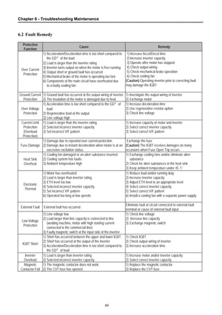
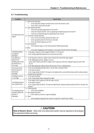
![Chapter 6 - Troubleshooting Maintenance
82
6.3.1 Motor Does Not RUN
NoCharge LED ON?
Yes
Inverter TroubleYesInput Power ON?
RST or BX
Terminal OFF?
Check RST, BX
Terminal Input
No
FUN 02
Set to 'Key'?
Yes
FUN 02 set to
'Terminal 1' or 2?
No
FUN 01
Set to 'Key'?
Check FX, RX
Terminal Input
Yes
FUN 01
Set to 'Terminal'?
No
Freq. Set
in DRV 00?
Yes
Voltage Output
at U,V,W?
Yes
Check Output Wiring
and Motor
Yes
Command freq. Higher
than FUN06?
Yes
Analog Signal
V1-5G or I-5G?
Yes
Yes Set Commnad freq.
higher than Starting
freq. [FUN 06]
No
Iverter Trouble
Yes
* Please check if the Run
Prevetion is set correctly in
FUN 03
No](https://image.slidesharecdn.com/sv-ih-140613211445-phpapp01/85/Sv-i-h-83-320.jpg)
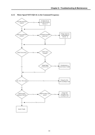
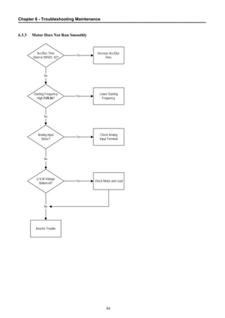
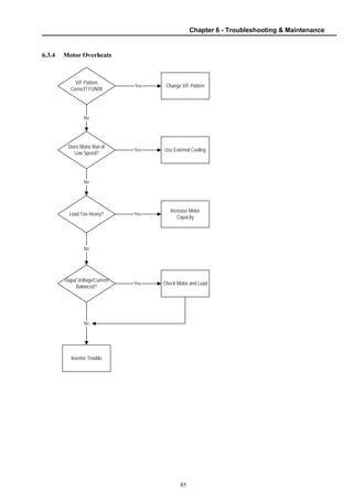
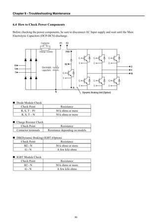
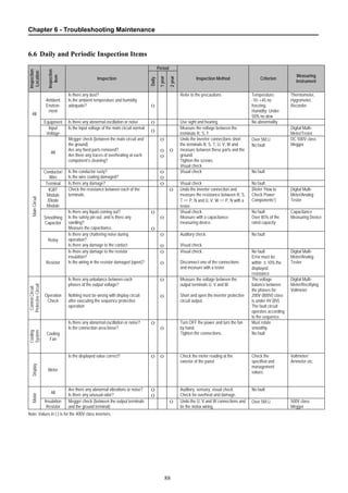
![89
APPENDIX A - FUNCTIONS BASED ON USE
Set the function properly according to the load and operating conditions. Application and related functions
are listed in the following table.
Use Related Parameter Code
Accel/Decel Time, Pattern Adjustment
DRV-01 [Acceleration Time], DRV-02 [Deceleration Time],
FUN 11 [Acceleration Pattern], FUN 12 [Deceleration Pattern]
Reverse Rotation Prevention FUN 03 [Forward, Reverse Prevention]
Minimum Accel/Decel Time FUN 11 [Acceleration Pattern], FUN 12 [Deceleration Pattern]
Accel/Decel at Continuous Rating Range FUN 11 [Acceleration Pattern], FUN 12 [Deceleration Pattern]
Braking Operation Adjustment FUN 15 [Stop Method], FUN 33~36 [DC Braking],
Operations for Frequencies Over 60 Hz
FUN 04 [Maximum Frequency],
FUN 25~26 [Frequency Limit]
Selecting an Appropriate Output
Characteristics for the Load
FUN 03 [Maximum Frequency],
FUN 05 [Base Frequency]
Motor Output Torque Adjustment
FUN 05 [Starting Frequency],
FUN 09~10 [Torque Boost],
FUN 45~46 [Stall Prevention],
FUN 39~40 [Rated Motor]
Output Frequency Limit
FUN 25~27 [Frequency Upper/Lower Limit],
I/O 20~24 [Analog Frequency Setting]
Motor Overheat Protection FUN 51~53 [Electronic Thermal], FUN 38~40 [Rated Motor]
Multi Step Operation
I/O 01~06 [Define the Multi Function Input Terminals],
I/O 12~19 [Jog, Multi Step Frequency],
FUN 25~27 [Frequency Upper/Lower Limit]
Jog Operation I/O 12 [Jog Frequency]
Frequency Jump Operation FUN 28~32 [Frequency Jump]
Timing the Electronic Brake Operation
I/O 39~40 [Frequency Detection Level],
I/O 07~11 [Multi Function Output]
Displaying the Rotating Speed
DRV 04 [Motor Speed],
FUN 41~42 [Motor RPM Display Gain]
Function Alteration Prevention FUN 98 [Parameter Lock]
Energy Saving FUN 14 [Energy Saving]
Auto Restart Operation After Alarm Stop FUN 42~43 [Auto Retry]
PID Feedback Operation FUN 62~72 [PID Operation]
Frequency Reference Signal and Output
Adjusting
FUN 20~24 [Analog Frequency Setting]
Define the Multi-Function Input Terminals I/O 01~06 [Define the Multi-Function Input Terminals]
Define the Multi-Function Input Terminals I/O 07~11 [Multi Function Auxiliary Contact Output Setting]
Commercial Line ⇔ inverter Switchover
Operation
I/O 01~06 [Define the Multi-Function Input Terminals],
I/O 07~11 [Multi-Function Auxiliary Contact Output Setting]
Frequency Meter Calibration I/O 34~37 [FM Output]
Operate by Communicating with a Computer
I/O 50 [Inverter No.],
I/O 51 [communication Speed]
I/O 52 [communication Timeout]](https://image.slidesharecdn.com/sv-ih-140613211445-phpapp01/85/Sv-i-h-90-320.jpg)
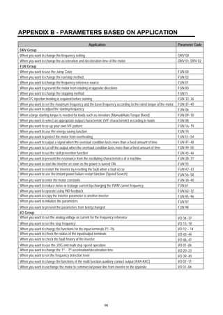
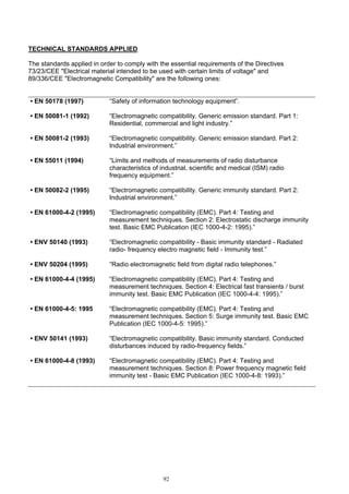
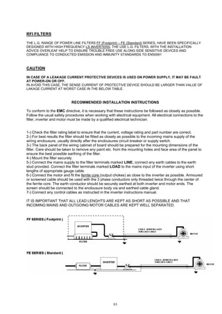
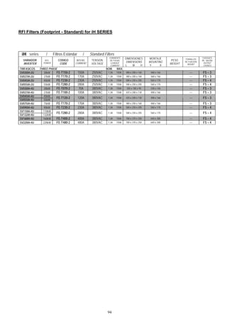
![96
UL MARKING
1. Short Circuit Rating
“Suitable For Use On A Circuit Capable Of Delivering Not More Than Table1 RMS Symmetrical Amperes,
240V for rated 240V drives, 480V for rated 480V drives Volts Maximum,” or equivalent.
Table 1. RMS Symmetrical Amperes for iH series.
Model Rating
SV030iH-4U, SV037iH-4U 5,000A
SV045iH-4U, SV055iH-4U, SV075iH-4U, SV090iH-4U, SV110iH-4U, SV132iH-4U 10,000A
SV160iH-4U, SV220iH-4U 18,000A
2. SHORT CIRCUIT FUSE/BREAKER MARKING
Use Class H or K5 UL Listed Input Fuse and UL Listed Breaker Only. See the table below for the Voltage
and Current rating of the fuses and the breakers.
External Fuse Breaker Internal Fuse
Input
Voltage
Motor
[kW]
Inverter Current
[A]
Voltage
[V]
Current
[A]
Voltage
[V]
Current
[A]
Voltage
[V]
Manufacturer Model Number
30 SV030iH-4U 100 500 100 460 125 600 Hinode Elec. 600FH-125S
37 SV037iH-4U 100 500 225 460 150 600 Hinode Elec. 600FH-150S
45 SV045iH-4U 100 500 225 460 200 600 Hinode Elec. 600FH-200S
55 SV055iH-4U 150 500 225 460 200 600 Hinode Elec. 600FH-200S
75 SV075iH-4U 200 500 225 460 125 600 Hinode Elec. 600FH-125S
90 SV090iH-4U 250 500 400 460 200 600 Hinode Elec. 600FH-200S
110 SV110iH-4U 300 500 400 460 200 600 Hinode Elec. 600FH-200S
132 SV132IH-4U 400 500 400 460 300 600 Hinode Elec. 600FH-300S
160 SV160iH-4U 400 500 400 460 300 600 Hinode Elec. 600FH-300S
400V
CLASS
220 SV220iH-4U - - 600 460 600 600 Hinode Elec. 600SPF-600UL
3. OVERLOAD PROTECTION
OC Limit : Inverter shuts off its output when inverter output current exceeds its overload trip level (FUN-
49 OC lim. Level)for overload trip time. (FUN-50 OC lim.time)
4. OVER SPEED PROTECTION
“Not Provided With Overspeed Protection”.](https://image.slidesharecdn.com/sv-ih-140613211445-phpapp01/85/Sv-i-h-97-320.jpg)
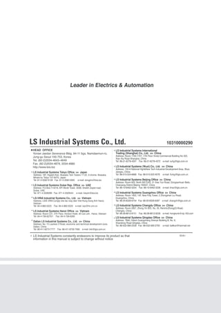

1) This document provides safety instructions and operating precautions for using an LS Variable Frequency Drive. It outlines potential hazards and proper safety procedures to prevent accidents. 2) Warnings and cautions are provided throughout regarding electric shock, improper wiring, operating errors, environmental conditions, and maintenance procedures. 3) Quick reference guides are included at the beginning and end to help users understand specifications, installation, operation, parameters, troubleshooting and more for maximizing performance of the inverter.


![Ct2000 pro plus_manual_english[1]](https://cdn.slidesharecdn.com/ss_thumbnails/ct2000proplusmanualenglish1-140613213527-phpapp02-thumbnail.jpg?width=640&height=640&fit=bounds)


![Ct2000 es manual_english_version_1[1].0](https://cdn.slidesharecdn.com/ss_thumbnails/ct2000esmanualenglishversion11-140613213448-phpapp01-thumbnail.jpg?width=640&height=640&fit=bounds)


