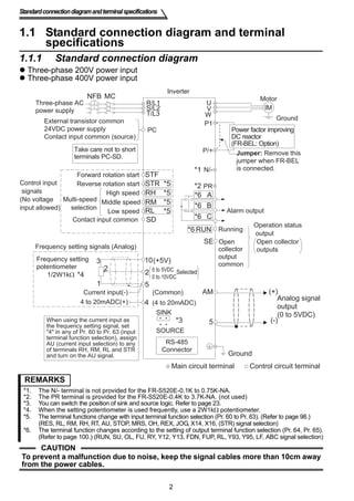
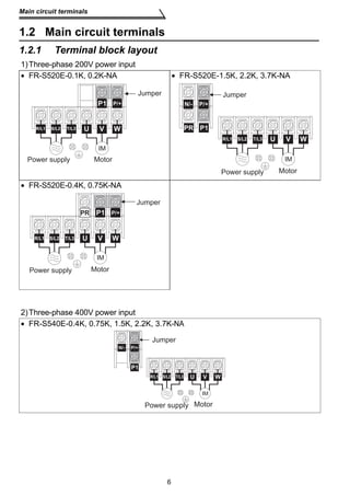
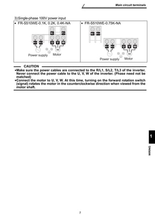
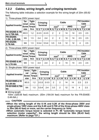
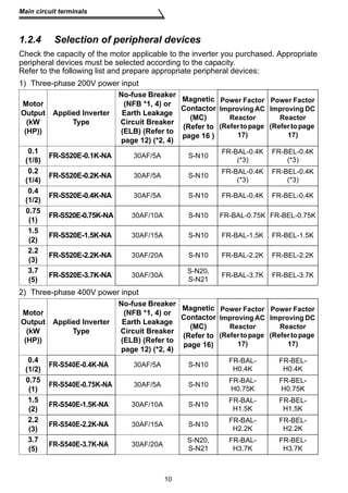
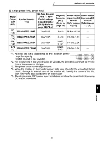
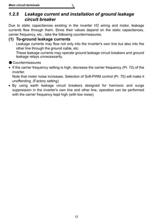
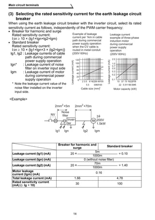
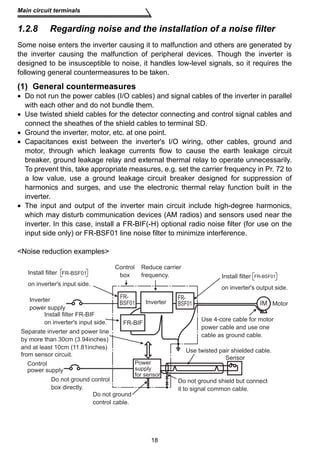
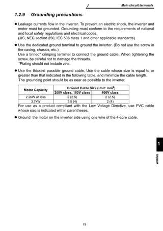
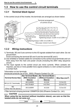
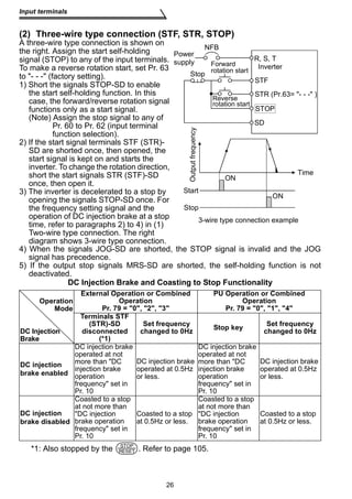
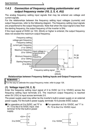
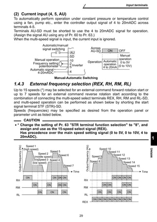
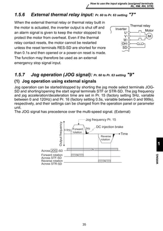
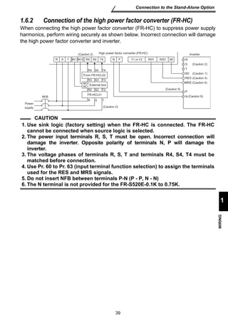
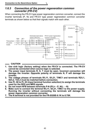
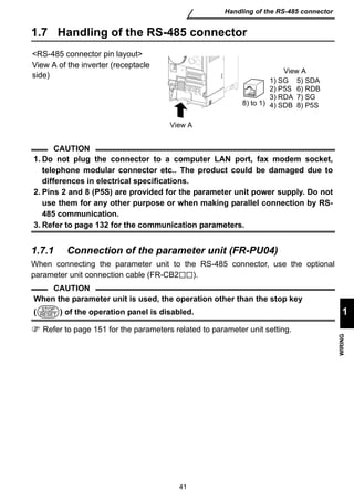
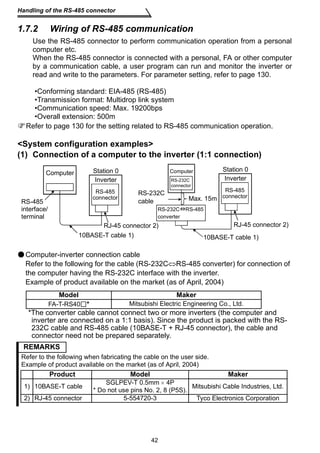
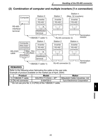
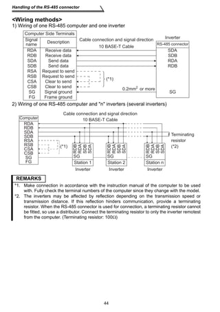
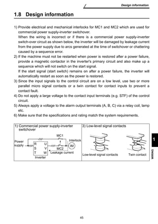
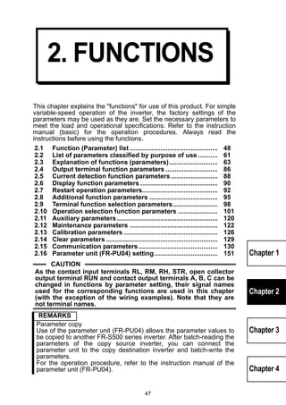
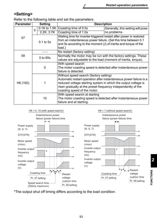
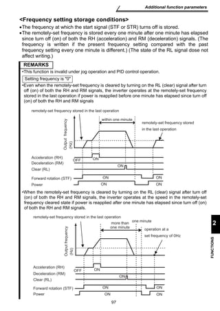
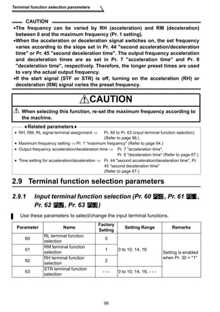
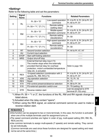
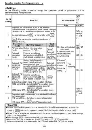
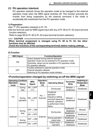
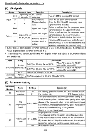
This document provides instructions for wiring and operating Mitsubishi transistorized inverters, including the FR-S500 series. It contains chapters on wiring, functions, protective functions, specifications, and safety. The document emphasizes safety precautions to prevent electric shock, fire, injury, and improper use. It provides guidance on transportation, installation, wiring, trial runs, operation, maintenance, inspection, and disposal of the inverters.
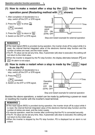
![Thank you for choosing this Mitsubishi Transistorized inverter.
This instruction manual (detailed) provides instructions for advanced use of the FR-S500
Incorrect handling might cause an unexpected fault. Before using the inverter, always
read this instruction manual and the instruction manual (basic) [IB-0600210ENG]
packed with the product carefully to use the equipment to its optimum.
This section is specifically about safety matters
Do not attempt to install, operate, maintain or inspect the inverter until you have read
through this instruction manual (basic) and appended documents carefully and can
use the equipment correctly. Do not use the inverter until you have a full knowledge
of the equipment, safety information and instructions.
In this instruction manual (detailed), the safety instruction levels are classified into
"WARNING" and "CAUTION".
Assumes that incorrect handling may cause hazardous
conditions, resulting in death or severe injury.
Assumes that incorrect handling may cause hazardous
conditions, resulting in medium or slight injury, or may cause
physical damage only.
WARNING
CAUTION
CAUTION
Note that even the level may lead to a serious consequence
according to conditions. Please follow the instructions of both levels because they are
important to personnel safety.
A-1
series inverters.
1. Electric Shock Prevention
WARNING
While power is on or when the inverter is running, do not open the front cover. You
may get an electric shock.
Do not run the inverter with the front cover or wiring cover removed. Otherwise,
you may access the exposed high-voltage terminals or the charging part of the
circuitry and get an electric shock. Also, the inverter's ability to withstand
earthquakes will deteriorate.
Even if power is off, do not remove the front cover except for wiring or periodic
inspection. You may access the charged inverter circuits and get an electric shock.
Before starting wiring or inspection, check to make sure that the 3-digit LED inverter
monitor is off, wait for at least 10 minutes after the power supply has been switched
off, and check to make sure that there are no residual voltage using a tester or the
like.
This inverter must be grounded. Grounding must conform to the requirements of
national and local safety regulations and electrical codes. (JIS, NEC section 250,
IEC 536 class 1 and other applicable standards)
Any person who is involved in the wiring or inspection of this equipment should be
fully competent to do the work.
Always install the inverter before wiring. Otherwise, you may get an electric shock
or be injured.
Perform setting dial and key operations with dry hands to prevent an electric
shock.
Do not subject the cables to scratches, excessive stress, heavy loads or pinching.
Otherwise, you may get an electric shock.
Do not change the cooling fan while power is on. It is dangerous to change the
cooling fan while power is on.
When you have removed the front cover, do not touch the connector above the 3-
digit monitor LED display. Otherwise, you get an electrick shock.](https://image.slidesharecdn.com/mitsubishi-s500e-vfd-detailed-manual-140830020319-phpapp02/85/Mitsubishi-s500-e-vfd-detailed-2-320.jpg)
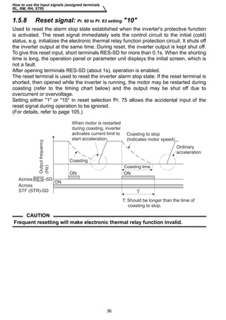
![A-3
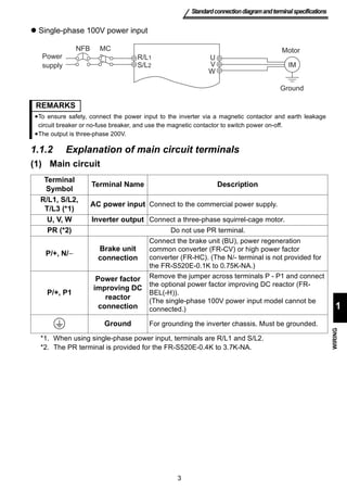
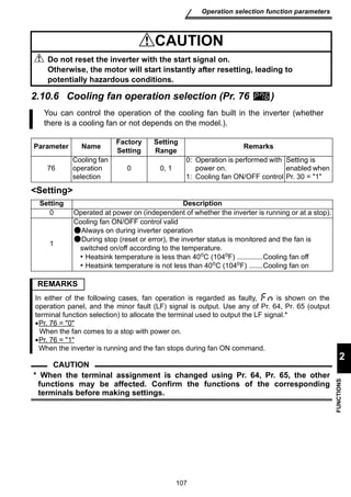
(2) Wiring
(3) Trial run
(4) Operation
CAUTION
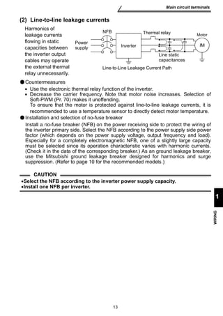
Do not fit capacitive equipment such as power factor correction capacitor, radio
noise filter (option FR-BIF(-H)) or surge suppressor to the output of the inverter.
The connection orientation of the output cables U, V, W to the motor will affect the
direction of rotation of the motor.
CAUTION
Check all parameters, and ensure that the machine will not be damaged by a
sudden start-up.
When the load GD2 is small (at the motor GD or smaller) for 400V from 1.5K to 3.7K, the
output current may vary when the output frequency is in the 20Hz to 30Hz range.
If this is a problem, set the Pr.72 PWM frequency selection to 6kHz or higher.
(When setting the PWM to a higher frequency, check for noise or leakage current
problem and take countermeasures against it.)
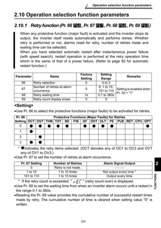
WARNING
When you have chosen the retry function, stay away from the equipment as it will
restart suddenly after an alarm stop.
The [STOP] key is valid only when the appropriate function setting has been made.
Prepare an emergency stop switch separately.
Make sure that the start signal is off before resetting the inverter alarm. A failure to
do so may restart the motor suddenly.
The load used should be a three-phase induction motor only. Connection of any
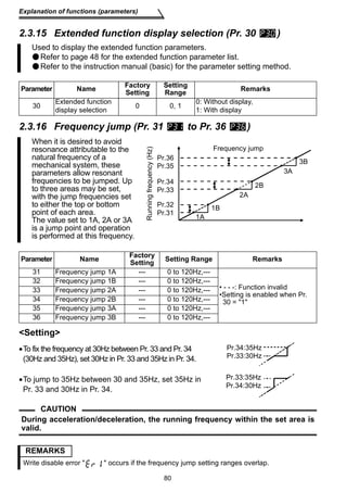
other electrical equipment to the inverter output may damage the equipment.
Do not modify the equipment.
Do not perform parts removal which is not instructed in this manual. Doing so may
lead to fault or damage of the inverter.](https://image.slidesharecdn.com/mitsubishi-s500e-vfd-detailed-manual-140830020319-phpapp02/85/Mitsubishi-s500-e-vfd-detailed-4-320.jpg)
![CPU
31
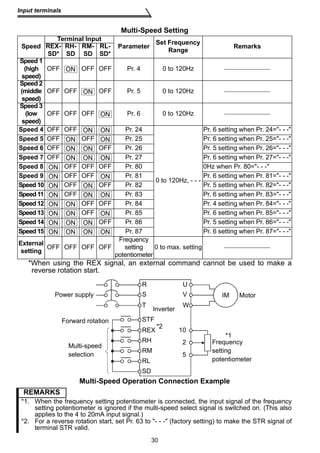
Input terminals
1
WIRING
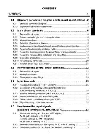
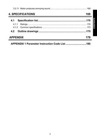
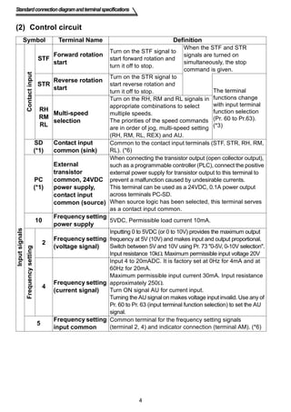
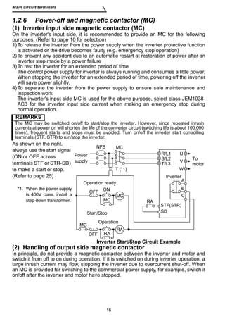
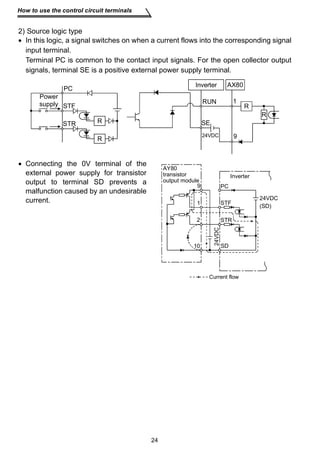
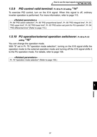
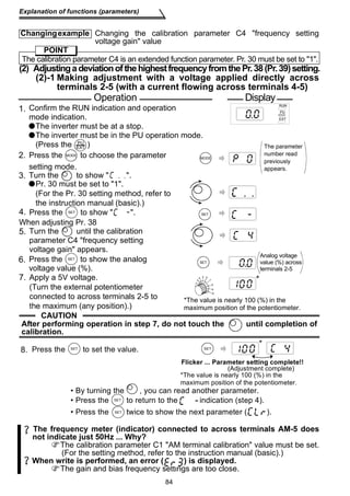
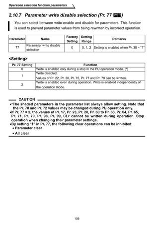
1.4.4 Indicator connection and adjustment (AM)
A full-scale 5VDC analog signal can
be output from across terminals AM-
5.
The analog output level can be
calibrated by the operation panel or
parameter unit (FR-PU04). Terminal
AM function selection can be set in
Pr. 54 AM terminal function
selection.
Terminal AM is isolated from the
control circuit of the inverter. The
cable length should not exceed
30m.
The output signal from terminal AM
delays about several 100ms in
output and therefore cannot be used
as a signal for control which requires
fast response.
AM
5
Meter
5V full scale
Analog meter
Terminal AM Output Circuit
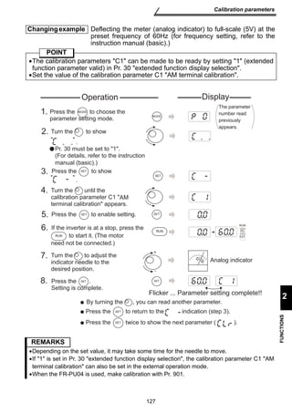
Set the reference output value of the inverter which outputs the full-scale voltage
5VDC.
Set it in Pr. 55 for frequency monitoring reference, or in Pr. 56 for current monitoring
reference.
Use the terminal AM output calibration parameter C1 to adjust the output voltage.
[Example] 1. To set the output across AM-5 to 5VDC at the inverter output
frequency of 90Hz, set 90Hz in Pr. 55. (Factory setting: 50Hz)
2. To set the output across AM-5 to 5VDC at the inverter output current of
20A, set 20A in Pr. 56. (Factory setting: rated inverter current)
CAUTION
•Refer to page 126 for the procedure of indicator adjustment.
AM
5 5VDC
Inverter
AM
circuit
Adjustment](https://image.slidesharecdn.com/mitsubishi-s500e-vfd-detailed-manual-140830020319-phpapp02/85/Mitsubishi-s500-e-vfd-detailed-41-320.jpg)
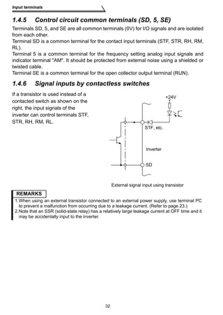
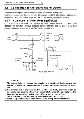


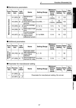
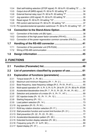
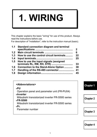
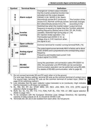
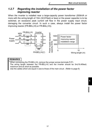
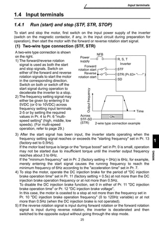
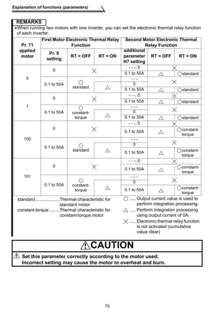
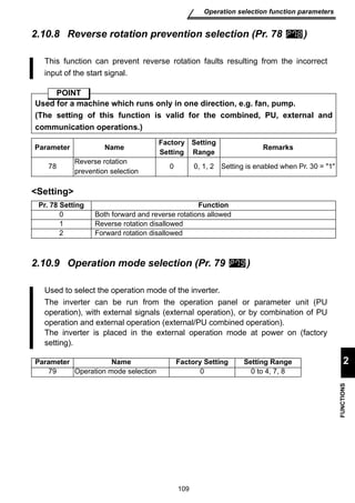
![Set the motor used and protect the motor from overheat.
This feature provides the optimum protective characteristics, including reduced
motor cooling capability, at low speed.
•When using the Mitsubishi constant-torque motor
Set 1 in Pr. 71 for V/F control or automatic torque boost control.
The electronic thermal relay function is set to the thermal characteristic of the
constant-torque motor.
•When you selected the Mitsubishi constant-torque motor, the values of the following
parameters are automatically changed. (only when the setting values of those
parameters are at factory setting)
Pr. 0 torque boost, Pr. 12 DC injection brake voltage
Para
meter Name Factory
Setting
Range Remarks
Rated output
current 0 to 50A
71 Applied motor 0 0, 1,
100, 101
Second electronic
thermal O/L relay - - - 0 to 50A,
- - -
Pr. 71 Setting Thermal Characteristic of the ElectronicThermal Relay Function
0, 100 Thermal characteristics of a standard motor
1, 101 Thermal characteristics of a Mitsubishi constant-torque motor
(This provides a 100% continuous torque characteristic in the low-speed region.)
69
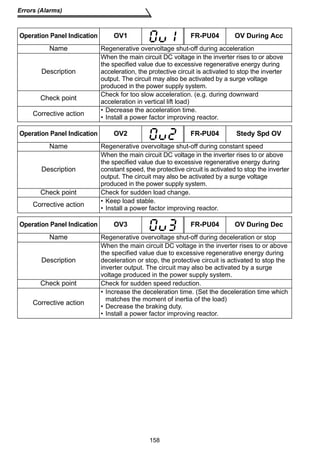
Explanation of functions (parameters)
2
FUNCTIONS
2.3.6 Selection and protection of a motor (Pr. 9 , Pr. 71 , H7 )
POINT
Setting
9 Electronic thermal
O/L relay
Setting is
enabled
when
Pr. 30 = 1
H7
(559)
- - -: Without second electronic
thermal relay function
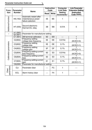
• The parameter number in parentheses is the one for use with the parameter unit (FR-PU04).
Setting
•Refer to the following list and set Pr. 71 according to the motor used.
Setting 100 or 101 changes thermal characteristic of the electronic thermal relay function
to thermal characteristics of a Mitsubishi constant-torque motor when the RT signal is ON.
•Set the rated current [A] of the motor in Pr. 9. (Normally set the rated current at 50Hz.)
•Setting 0 in Pr. 9 disables electronic thermal relay function (motor protective
function). (The protective function of the inverter is activated.)
•When setting second electronic thermal relay function, set the motor rated current
value in the additional parameter H7. The second electronic thermal relay function is
valid when the RT signal is on. (When the RT signal is on, other second functions
(Pr.44 to Pr.47) are also selected.)
CAUTION
•When two or more motors are connected to the inverter, they cannot be
protected by the electronic thermal relay function. Install an external thermal
relay to each motor.
•When a difference between the inverter and motor capacities is large and the
setting becomes less than half amount of the inverter rated current, the
protective characteristics of the electronic thermal relay function will be
deteriorated. In this case, use an external thermal relay.
•A special motor cannot be protected by the electronic thermal relay function.
Use an external thermal relay.](https://image.slidesharecdn.com/mitsubishi-s500e-vfd-detailed-manual-140830020319-phpapp02/85/Mitsubishi-s500-e-vfd-detailed-79-320.jpg)
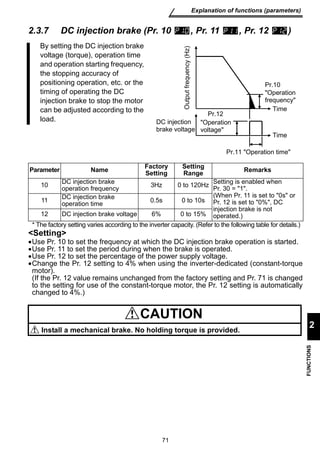
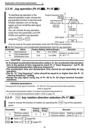
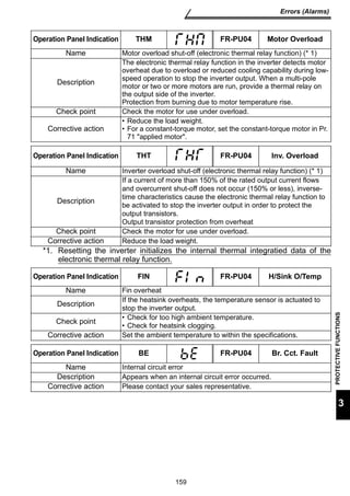
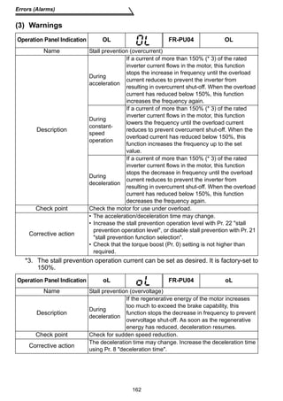
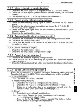
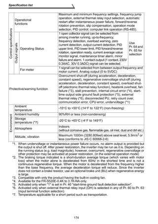
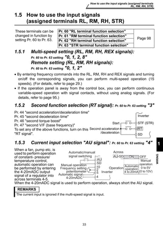
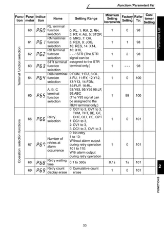
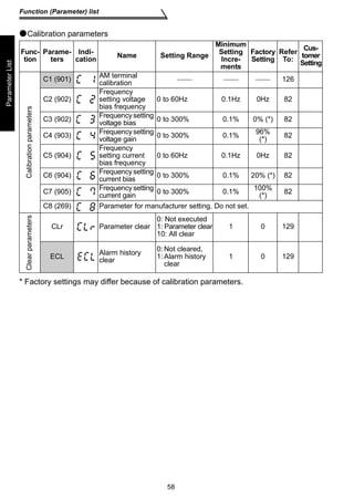
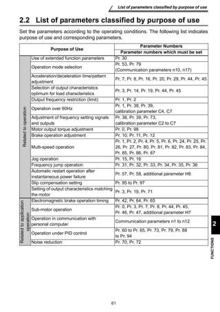
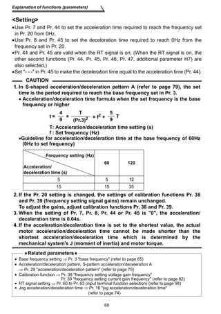
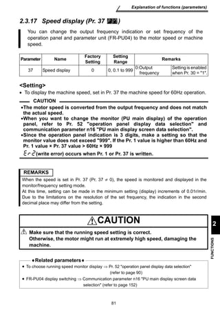
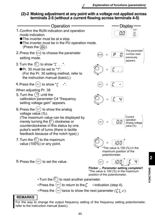
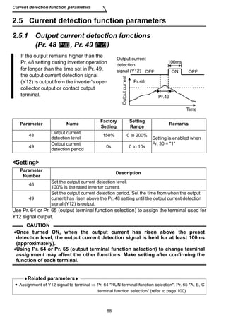
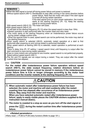
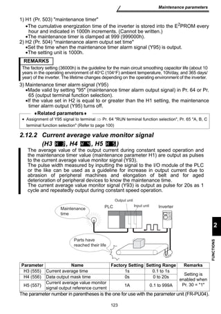
![Set the output current level (% value to the inverter rated current) at which the
output frequency will be adjusted to prevent the inverter from stopping due to
overcurrent etc.
During high-speed operation above the rated motor frequency, acceleration
may not be made because the motor current does not increase. To improve
the operating characteristics of the motor in this case, the stall prevention
level can be reduced in the high frequency region. This function is effective for
performing operation up to the high speed range on a centrifugal separator
etc. Normally, set 60Hz in Pr. 28 stall prevention operation reduction starting
frequency and 100% in Pr. 23.
Parameter Name Factory
Setting
level 150% 0 to 200%
- - - 0 to 200%,
reduction starting frequency 60Hz 0 to 120Hz
When Pr.23 =- - -
Pr.23
120Hz
Pr.22
Pr.28
Stall prevention
operation level (%)
Reduction ratio
compensation factor (%)
Output
frequency (Hz)
Setting example
150%,
(Pr.22=
Pr.23=100%, Pr.28= Hz)
150
112.5
90
75
0 80100120
Stall prevention
operation level (%)
60
Output
frequency (Hz)
60
Stall prevention operation level (%) = A + B ×[ Pr. 22-A ]×[ Pr. 23-100 Pr. 22-B 100 ]
where, A = Pr. 28 (Hz) × Pr. 22 (%) , B = Pr. 28 (Hz) × Pr. 22 (%)
output frequency (Hz) 120Hz
77
Explanation of functions (parameters)
2
FUNCTIONS
2.3.13 Stall prevention (Pr. 22 , Pr. 23 , Pr. 28 )
Setting
Range Remarks
22 Stall prevention operation
Setting is
enabled
when
Pr. 30 = 1.
23
Stall prevention operation
level compensation factor at
double speed
- - -
- - -: Pr. 22
equally
28 Stall prevention operation
Setting
•Generally, set 150% (factory setting) in Pr. 22 stall prevention operation level.
Setting 0 in Pr. 22 disables stall prevention operation.
•To reduce the stall prevention operation level in the high frequency range, set the
reduction starting frequency in Pr. 28 stall prevention operation reduction starting
frequency and the reduction ratio compensation factor in Pr. 23.
Formula for stall prevention operation level
•By setting - - - (factory setting) in Pr. 23, the stall prevention operation level is
constant at the Pr. 22 setting up to 120Hz.](https://image.slidesharecdn.com/mitsubishi-s500e-vfd-detailed-manual-140830020319-phpapp02/85/Mitsubishi-s500-e-vfd-detailed-87-320.jpg)
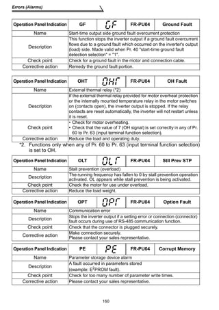
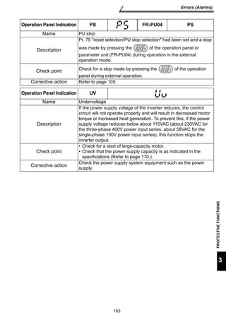
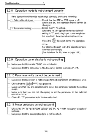
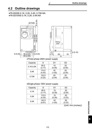
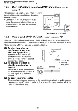
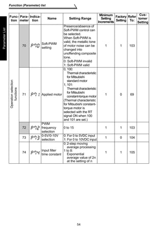
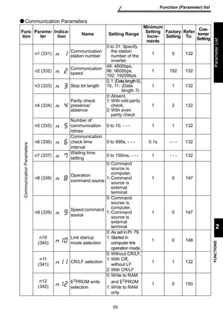
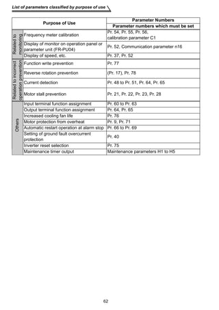
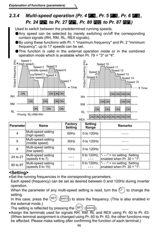
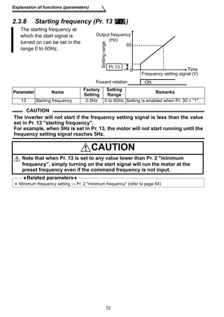
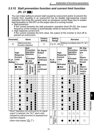
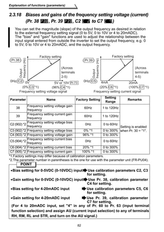
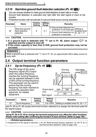
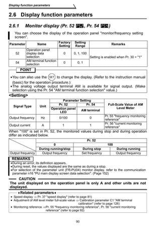
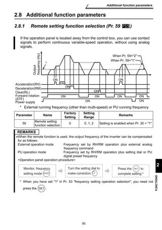
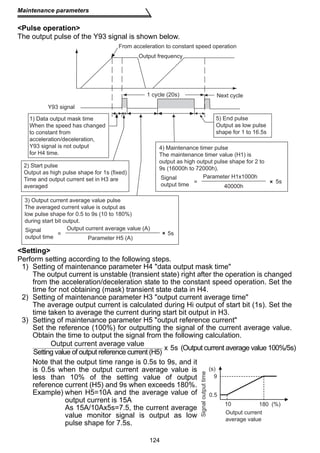
![Set the acceleration/deceleration pattern.
Set value 1
[S-pattern
acceleration/deceleration A]
79
Explanation of functions (parameters)
2
FUNCTIONS
2.3.14 Acceleration/deceleration pattern (Pr. 29 )
fb
Output
frequency (Hz)
Set value 0
[Linear
acceleration/deceleration]
Time
Output
frequency (Hz)
Parameter Name Factory
Setting
Setting
Set value 2
[S-pattern
acceleration/deceleration B]
Output
frequency (Hz)
Time
f1
f2
Setting
Range Remarks
29 Acceleration/
Time
deceleration pattern 0 0, 1, 2 Setting is enabled when Pr. 30 = 1.
Pr. 29
Setting Function Description
0
Linear
acceleration/
deceleration
Acceleration is made to the set frequency linearly.
(Factory setting)
1
S-pattern
acceleration/
deceleration A (*)
For machine tool spindle applications, etc.
Used when acceleration/deceleration must be made in a short
time to a high-speed region of not lower than the base
frequency. Acceleration/deceleration is made in a pattern
where fb (base frequency) acts as the inflection point of an S
shape, and you can set the acceleration/deceleration time
which matches the motor torque reduction in the constant-output
operation region of not lower than the base frequency.
2
S-pattern
acceleration/
deceleration B
For prevention of load shifting in conveyor and other
applications. Since acceleration/deceleration is always made in
an S shape from f2 (current frequency) to f1 (target frequency),
this function eases shock produced at acceleration/
deceleration and is effective for load collapse prevention, etc.
CAUTION
* As the acceleration/deceleration time, set the time taken to reach the Pr. 3
base frequency value, not the Pr. 20 acceleration/deceleration reference
frequency value.
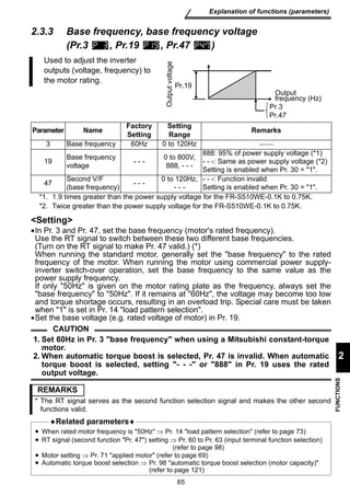
♦Related parameters♦
• Base frequency (acceleration/deceleration time setting) setting ⇒ Pr. 3 base frequency
(refer to page 65)
• Pr. 20 acceleration / deceleration reference frequency ⇒ refer to page 67
• For setting of 1 (S-pattern acceleration/deceleration A)
⇒ Pr. 44 second acceleration/deceleration time, Pr. 45 second deceleration time (refer to
page 67)](https://image.slidesharecdn.com/mitsubishi-s500e-vfd-detailed-manual-140830020319-phpapp02/85/Mitsubishi-s500-e-vfd-detailed-89-320.jpg)
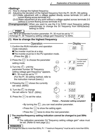
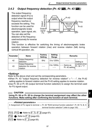
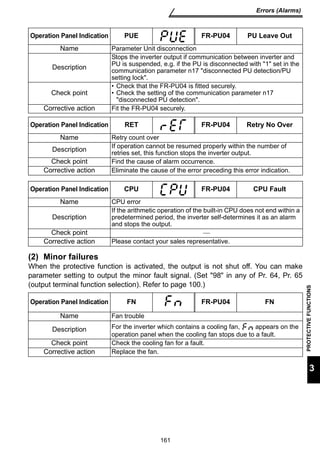
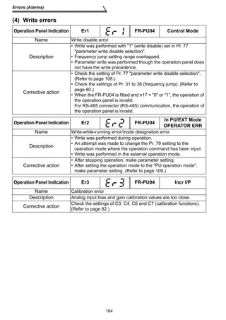
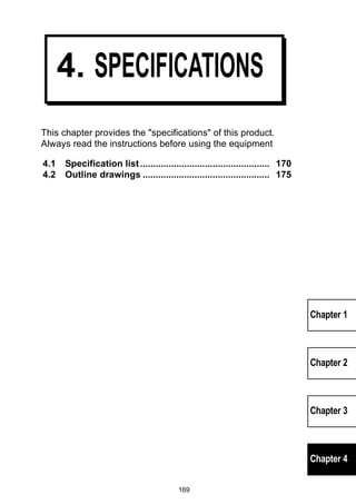
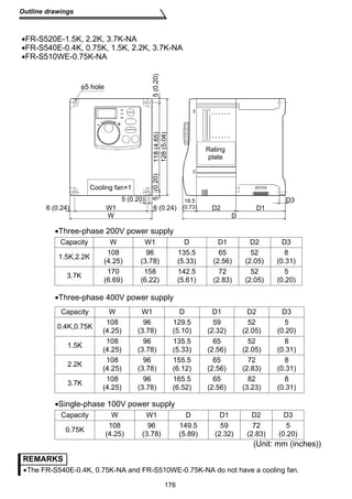
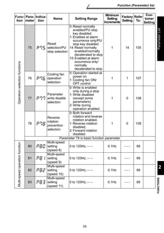
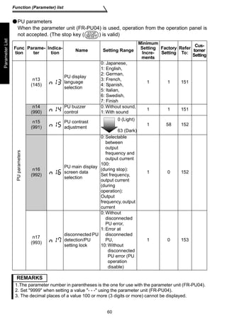
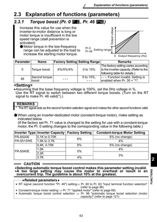
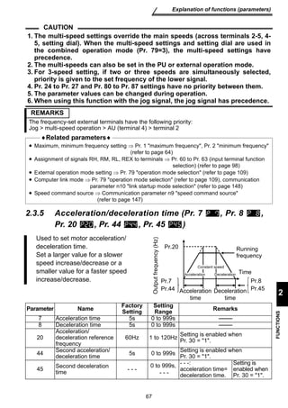
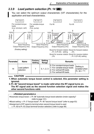
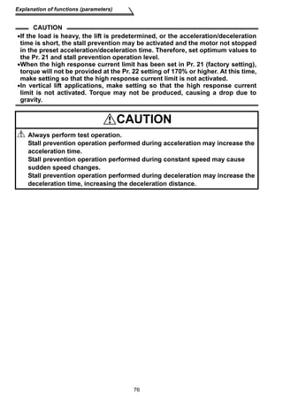
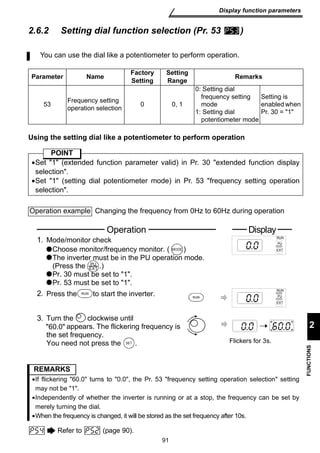
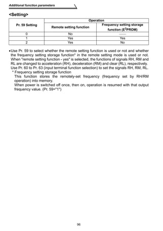
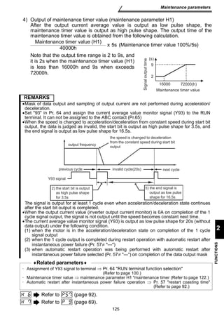
![When the inverter's
output current falls
Start signal OFF ON
to 0[A], torque will
not be generated.
This may cause a
Pr.50
100ms
gravity drop when
OFF OFF
the inverter is used
in vertical lift
application.
To prevent this, the output current zero signal can be output from the inverter
to close the mechanical brake when the output current has fallen to 0[A].
Parameter Name Factory
Setting
ON ON
Pr.51
detection period
Pr.51
detection period
50 Zero current detection level 5% 0 to 200% Setting is enabled when
51 Zero current detection period 0.5s 0.05 to 1s Pr. 30 = 1
POINT
If the output is lower than the Pr. 50 setting for longer than the time set in Pr.
51 during inverter operation, the zero current detection (Y13) signal is output
from the inverter's open collector output terminal or contact output terminal.
Parameter Description
Set the zero current detection level.
Set the level of zero current detection in terms of the percentage of the rated
inverter current from the output current value of 0 [A].
Set the zero current detection period.
Set a period of time from when the output current falls to or below the Pr. 50
setting to when the zero current detection signal (Y13) is output.
89
Current detection function parameters
2
FUNCTIONS
2.5.2 Zero current detection (Pr. 50 , Pr. 51 )
Setting
Setting
Range Remarks
50
51
Use Pr. 64 or Pr. 65 (output terminal function selection) to assign the terminal used for
Y13 signal output.
CAUTION
•If the current falls below the preset detection level but the timing condition is
not satisfied, the zero current detection signal is held on for about 100ms.
•When the terminal functions are changed using Pr. 64, Pr. 65, the other
functions may be affected. Please make setting after confirming the function
of each terminal.
•When running (connecting) multiple motors with one inverter in due order, the
zero current detection signal (Y13) may be output. Set 13% or more for the 0.1K
and 8% or more for the 0.2K.
(when the total capacity of motors is less than the zero current detection level
and the motor capacity per inverter is less than the zero current detection level)
♦Related parameters♦
• Assignment of Y13 signal to terminal ⇒ Pr. 64 RUN terminal function selection, Pr. 65 A, B, C
terminal function selection (refer to page 100)
Pr.50
zero
current
detection
level
Output
current 0 [A]
Zero current
detection signal
output (Y13)](https://image.slidesharecdn.com/mitsubishi-s500e-vfd-detailed-manual-140830020319-phpapp02/85/Mitsubishi-s500-e-vfd-detailed-99-320.jpg)
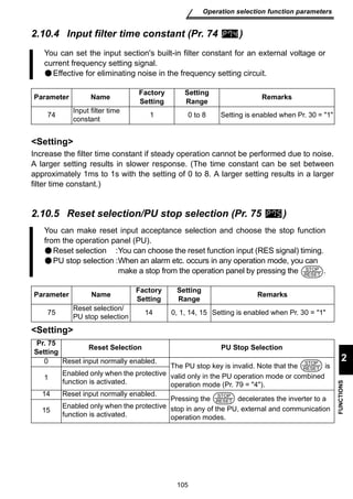
![You can change the motor sound.
Parameter Name Factory
103
Operation selection function parameters
2
FUNCTIONS
2.10.2 PWM carrier frequency (Pr. 70 , Pr. 72 )
Setting
• By parameter setting, you can set whether to exercise Soft-PWM control that
changes the motor tone.
• Soft-PWM control is a control system that changes the motor noise from a metallic
tone into an unoffending complex tone.
Refer to (page 69).
Setting
Setting
Range Remarks
70 Soft-PWM setting 1 0, 1 Setting is enabled when
72 PWM frequency selection 1 0 to 15 Pr. 30 = 1
Pr.70 Setting Description
0 Soft-PWM invalid
1 When Pr. 72=0 to 5, Soft-PWM is made valid.
Pr.72 Setting Description
0 to 15
PWM carrier frequency can be changed.
The setting displayed is in [kHz].
Note that 0 indicates 0.7kHz and 15 indicates 14.5kHz.
REMARKS
•An increased PWM frequency will decrease the motor sound but increase noise and leakage
currents. Therefore, perform the reduction techniques. (Refer to page 18.)
•Metallic sound may be generated from the motor at sudden deceleration but it is not a fault.](https://image.slidesharecdn.com/mitsubishi-s500e-vfd-detailed-manual-140830020319-phpapp02/85/Mitsubishi-s500-e-vfd-detailed-113-320.jpg)
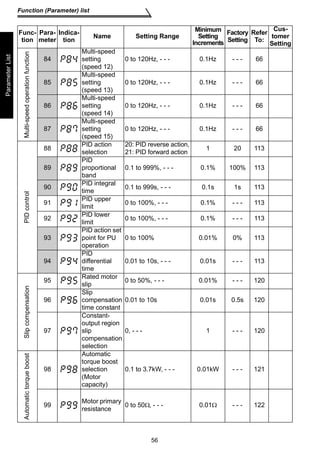
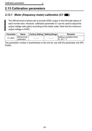
![The inverter can be used to exercise process control, e.g. flow rate, air volume
or pressure.
The voltage input signal (0 to +5V or 0 to +10V) or Pr. 93 setting is used as a
set point and the 4 to 20mADC current input signal used as a feedback value
to constitute a feedback system for PID control.
Made valid by turning on the X14 signal. Use Pr. 60 to Pr. 63 (input terminal function
selection) to make assignment.
Parameter Name Factory
Inverter circuit :
PID operation
+- IM
Set point
1
Kp 1+ +Td S
Ti S
Terminal 4
Kp: Proportion constant Ti: Integral time S: Operator Td: Differential time
113
Operation selection function parameters
2
FUNCTIONS
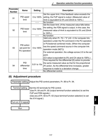
2.10.10 PID control (Pr. 88 to Pr. 94 )
POINT
Setting
(1) Basic PID control configuration
(2) PID action overview
Setting Setting Range Remarks
88 PID action selection 20 20, 21
Setting is enabled
when Pr. 30 = 1
89 PID proportional band 100% 0.1 to 999%, - - -
90 PID integral time 1s 0.1 to 999s, - - -
91 PID upper limit - - - 0 to 100%, - - -
92 PID lower limit - - - 0 to 100%, - - -
93 PID action set point for PU
operation 0% 0 to 100%
94 PID differential time - - - 0.01 to 10s, - - -
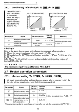
1) PI action
A combination of proportional control
action (P) and integral control action (I)
for providing a manipulated variable in
response to deviation and changes
with time.
[Operation example for stepped
changes of measured value]
REMARKS
PI action is the sum of P and I actions.
Manipulated
variable
Motor
Feedback signal (Measured value)
Pr. 93 or Treminal 2
Deviation Set point
Measured value
Time
Time
Time
P action
I action
PI action](https://image.slidesharecdn.com/mitsubishi-s500e-vfd-detailed-manual-140830020319-phpapp02/85/Mitsubishi-s500-e-vfd-detailed-123-320.jpg)
![114
Operation selection function parameters
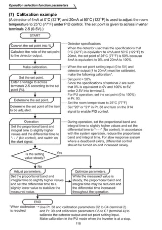
2) PD action
A combination of proportional control
action (P) and differential control action
(D) for providing a manipulated
variable in response to deviation speed
to improve the transient characteristic.
[Operation example for proportional
changes of measured value]
REMARKS
PD action is the sum of P and D actions.
3) PID action
The PI action and PD action are
combined to utilize the advantages of
both actions for control.
REMARKS
The PID action is the sum of P, I and D actions.
4) Reverse action
Increases the manipulated
variable (output frequency) if
deviation X = (set point -
measured value) is positive, and
decreases the manipulated
variable if deviation is negative.
Deviation
Set point
Time
Time
Time
P action
D action
PD action
Measured
value
Deviation
Time
Time
Time
P action
D action
PID action
Set point
Measured
value
Time
I action
y=at 2 +bt+c
Set point
[Heating]
+
-
Feedback signal
(Measured value)
Deviation
Set point
X0
X0
Cold up
Hot down
Measured value](https://image.slidesharecdn.com/mitsubishi-s500e-vfd-detailed-manual-140830020319-phpapp02/85/Mitsubishi-s500-e-vfd-detailed-124-320.jpg)
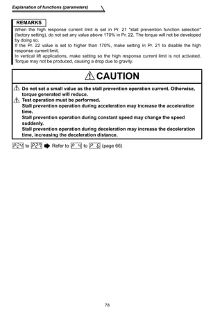
![Set point
Too cold down
Hot up
Inverter
R/L1
S/L2
T/L3
STF
STR
SD
RH(X14)(*3)
RUN(FUP,FDN)
10
2
5
4
UV
W
(*2)
SE
Pump
IM P
For
3-wire
type
- + + - +
A
C
Upper limit
(Lower limit)
Forward
rotation output
Reverse
rotation output
Forward (reverse)
rotation output
signal common
(Measured value) 4 to 20mA
0 24V
power supply (*1)
115
Operation selection function parameters
2
FUNCTIONS
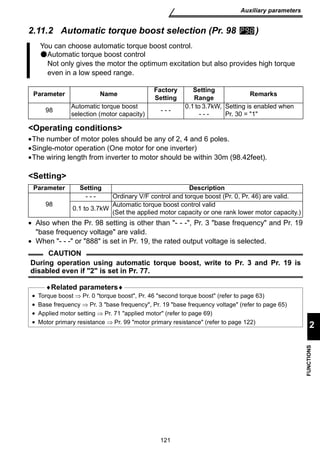
5) Forward action
Increases the manipulated
variable (output frequency) if
deviation X = (set point -
measured value) is negative,
and decreases the manipulated
variable if deviation is positive.
X0
X0
[Cooling]
+
-
Feedback signal
(Measured value)
Measured value
Set point
Deviation
Relationships between deviation and manipulated variable (output frequency)
(3) Wiring example
Deviation
Positive Negative
Reverse action
Forward action
•Pr. 60 = 14
•Pr. 64 = 15
•Pr. 65 = 16
•Pr. 88 = 20
Forward rotation
Reverse rotation
(Set point setting)
φ
AC1
200/220V 50/60Hz
CAUTION
Motor
Limit signal
common
For
2-wire
type
Detector
Power
supply
NFB
PID control
selection
Setting
potentiometer
(OUT) (COM) (24V)
*1.The power supply must be selected in accordance with the power
specifications of the detector used.
*2.The output signal terminals used depends on the Pr. 64, Pr. 65 settings.
*3.The input signal terminal used depends on the setting of Pr. 60 to Pr. 63.
•The contact input signal (AU Signal) need not be turned on.](https://image.slidesharecdn.com/mitsubishi-s500e-vfd-detailed-manual-140830020319-phpapp02/85/Mitsubishi-s500-e-vfd-detailed-125-320.jpg)
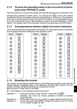
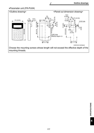
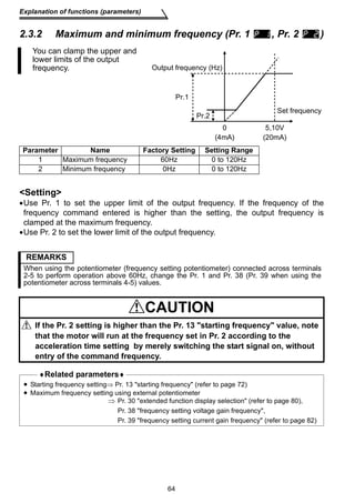
![[Detection value]
(%)
100
0
0 4 20 (mA)
119
Operation selection function parameters
2
FUNCTIONS
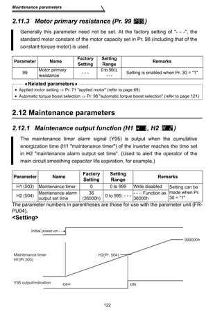
Set point input calibration
1. Apply the input voltage of 0% set point setting (e.g. 0V) across terminals 2-5.
2. Make calibration using the calibration parameters C2, C3. At this time, enter in C2
the frequency which should be output by the inverter at the deviation of 0% (e.g.
0Hz). (When using the FR-PU04, make calibration with Pr. 902.)
3. Apply the voltage of 100% set point (e.g. 5V) to across terminals 2-5.
4. Make calibration using Pr. 38 and calibration parameter C4. At this time, enter in Pr.
38 the frequency which should be output by the inverter at the deviation of 100%
(e.g. 60Hz). (When using the FR-PU04, make calibration with Pr. 903.)
Detector output calibration
1. Apply the output current of 0% detector setting (e.g. 4mA) across terminals 4-5.
2. Make calibration using the calibration parameter C6. (When using the FR-PU04,
make calibration with Pr. 904.)
3. Apply the output current of 100% detector setting (e.g. 20mA) across terminals 4-5.
4. Make calibration using the calibration parameter C7. (When using the FR-PU04,
make calibration with Pr. 905.)
Note: The frequencies set in the calibration parameter C5 and Pr. 39 should be equal
to those set in the calibration parameter C2 and Pr. 38, respectively.
The results of the above calibration are as shown below:
(%)
100
[Set point setting]
0
0 5 (V)
[Manipulated variable]
Manipulated
variable (Hz)
60
0
0 100 Deviation (%)
REMARKS
•If the multi-speed (RH, RM, RL signal) or jog operation (JOG signal) is entered, PID control is
stopped and multi-speed or jog operation is started.
•When the terminal functions are changed using Pr. 60 to Pr. 65, the other functions may be
affected. Confirm the functions of the corresponding terminals before making settings.
•When PID control is selected, the minimum frequency is the frequency set in the calibration
parameter C2 and the maximum frequency is the frequency set in Pr. 38.
(The Pr. 1 maximum frequency and Pr. 2 minimum frequency settings are also valid.)
♦Related parameters♦
• X14 signal assignment ⇒ Pr. 60 to Pr. 63 (input terminal function selection) (refer to page 98)
• FUP, FDN and RL signal assignment ⇒ Pr. 64 RUN terminal function selection, Pr. 65 A, B, C
terminal function selection (refer to page 100)
• Voltage input selection (0 to ±5V, 0 to ±10V) ⇒ Pr. 73 0-5V/0-10V selection
(refer to page 104)
• Operation mode selection ⇒ Pr. 79 operation mode selection (refer to page 109)
• Making terminal calibration ⇒ Pr. 38, Pr. 39, C2 to C7 (calibration parameters) (refer to page 82)](https://image.slidesharecdn.com/mitsubishi-s500e-vfd-detailed-manual-140830020319-phpapp02/85/Mitsubishi-s500-e-vfd-detailed-129-320.jpg)
![Auxiliary parameters
2.11 Auxiliary parameters
2.11.1 Slip compensation (Pr. 95 , Pr. 96 , Pr. 97 )
The inverter output current may be used to assume motor slip to keep the motor
speed constant.
Parameter Name Factory
Setting Setting Range Remarks
95 Rated motor slip - - - 0 to 50%, - - -
constant 0.5s 0.01 to 10s
compensation selection - - - 0, - - -
Rated slip = Synchronous speed at base frequency - rated speed Synchronous speed at base frequency ×100[%]
Parameter Setting Function
95 0.01 to 50% Used to set the rated motor slip.
0, - - - Slip compensation is not made.
96 0.01 to 10s Used to set the slip compensation response time. (*)
97 0 Slip compensation is not made in the constant output range
(frequency range above the frequency set in Pr. 3).
- - - Slip compensation is made in the constant output range.
120
96 Slip compensation time
97 Constant-output region slip
Setting
Setting is enabled
when Pr. 30 = 1
*When this value is made smaller, response will be faster.
However, as load inertia is greater, a regenerative overvoltage (OVT) error is
more liable to occur.
REMARKS
When making slip compensation at 60Hz, set the maximum frequency (Pr. 1) to slightly higher
than 60Hz.
In the factory setting status, it is clamped at 60Hz.](https://image.slidesharecdn.com/mitsubishi-s500e-vfd-detailed-manual-140830020319-phpapp02/85/Mitsubishi-s500-e-vfd-detailed-130-320.jpg)
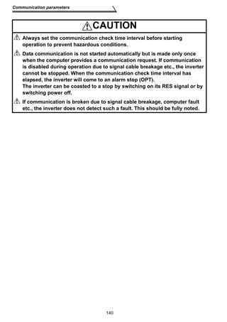
![Communication parameters
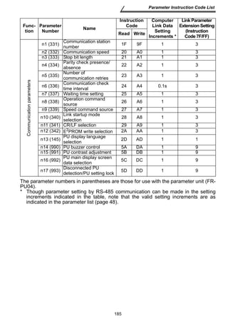
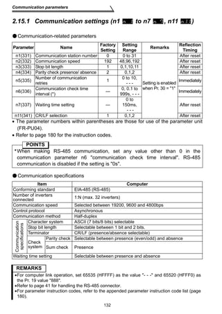
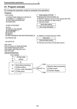
2.15 Communication parameters
You can perform communication operation from the RS-485 connector of the
inverter through RS-485.
Computer
link
operation
Switching by
computer program
Switching by operation panel
/parameter unit (FR-PU04)
External
operation
C
D
(Switching must not be made)
E
F
A
B
Symbol Switching Type Switching Method
PU
operation
PU
EXT PU EXT
Using the of the operation panel or the / of
the parameter unit (FR-PU04)
PU
EXT PU EXT
Using the of the operation panel or the / of
the parameter unit (FR-PU04)
Using the
computer program Read (H7B)/
Using the
computer program
Switching must not be made
(External operation may be selected at and then
switched to computer link operation at *)
E A
C
Switching must not be made
(External operation may be selected at and then
switched to PU operation at *)
F D
130
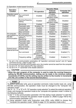
(1) Operational functions
1) Operation mode switching
[Operation mode switching method]
*1.
PU operation to external
operation
External operation to PU
operation
External operation to
computer link operation
Write (HFB)
H0000: Communication
operation
H0001: External
operation
Computer link operation to
external operation
PU operation to computer
link operation
Computer link operation to
PU operation
A
B
C
D
B
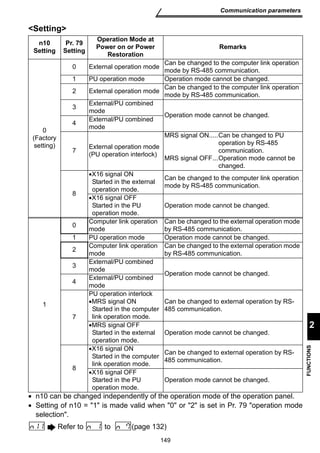
* When 1 is set in the communication parameter n10 link startup mode selection,
the inverter is placed in the computer link operation mode at power on or inverter
reset. (Note that it is overridden by the Pr. 79 operation mode selection setting.)
REMARKS
Unlike the other inverters, the FR-S500 series is not the type of inverter whose operation panel
is removed to make communication.
Parameter setting using setup S/W is not enabled in the PU operation mode and external / PU
combined operation mode (Pr. 79 = 1, 3, 4). Also, pressing the RUN
on the operation panel
starts the inverter in the external / PU combined operation mode. (Pr. 79=1, 3)](https://image.slidesharecdn.com/mitsubishi-s500e-vfd-detailed-manual-140830020319-phpapp02/85/Mitsubishi-s500-e-vfd-detailed-140-320.jpg)
![133
Communication parameters
2
FUNCTIONS
Setting
To make communication between the personal computer and inverter, initialization of
the communication specifications must be made to the inverter. If initial setting is not
made or there is a setting fault, data transfer cannot be made.
*After making the initial setting of the parameters, always reset the inverter. After you
have changed the communication-related parameters, communication cannot be
made until the inverter is reset.
Parameter Description Setting Description
n1 Communication
station number 0 to 31
Station number specified for communication from
the RS-485 connector.
Set the inverter station numbers when two or more
inverters are connected to one personal computer.
n2 Communication
speed
48 4800bps
96 9600bps
192 19200bps
n3 Stop bit length/
data length
8 bits 0 Stop bit length 1 bit
1 Stop bit length 2 bits
7 bits 10 Stop bit length 1 bit
11 Stop bit length 2 bits
n4
Parity check
presence/
absence
0 Absent
1 Odd parity present
2 Even parity present
n5
Number of
communication
retries
0 to 10
Set the permissible number of retries at occurrence
of a data receive error.
If the number of consecutive errors exceeds the
permissible value, the inverter will come to an alarm
stop (OPT).
---
(65535)
If a communication error occurs, the inverter will not
come to an alarm stop. At this time, the inverter can
be coasted to a stop by MRS or RES input.
During a communication error (H0 to H5), the minor
fault signal (LF) is switched on. Allocate the used
terminal with any of Pr. 64, Pr. 65 (output terminal
function selection).
n6
Communication
check time
interval
0 No communication
0.1 to 999
Set the communication check time [s] interval.
If a no-communication state persists for longer than
the permissible time, the inverter will come to an
alarm stop (OPT).
--- Communication check suspension.
n7 Waiting time
setting
0 to 150 Set the waiting time between data transmission to
the inverter and response.
--- Set with communication data.
n11 CR/LF selection
0 Without CR/LF
1 With CR, without LF
2 With CR/LF](https://image.slidesharecdn.com/mitsubishi-s500e-vfd-detailed-manual-140830020319-phpapp02/85/Mitsubishi-s500-e-vfd-detailed-143-320.jpg)
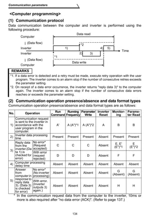
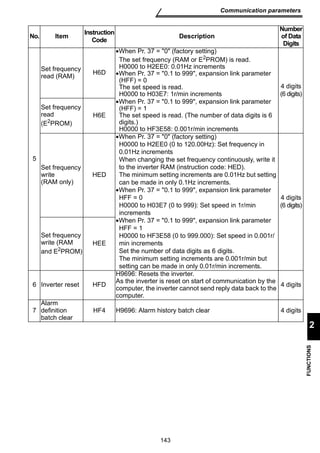
![REMARKS
*1. Setting any of 0.1 to 999 in Pr. 37 speed display and 1 in instruction code HFF sets
the data format to A or E (6-digit data). Also, the output frequency turns to a speed
display, which is valid in 0.01r/min increments. (The third decimal place is invalid.) If the
instruction code HFF is other than 1, the display is in 1r/min increments and a 4-digit
data format can be used. Reply data is given in format E if the requested monitor data has
4 digits, in format E' if the data has 2 digits, or in format E if the data has 6 digits.
*2. The data format to read/write Pr. 37 speed display is always E/A (6-digit data).
*3
Waiting
time
1 2 3 4 5 6 7 8 9 10 11 12 13
*3
Waiting
time
1 2 3 4 5 6 7 8 9 10 11
*3
Waiting
time
1 2 3 4 5 6 7 8 9 10 11 12 13 14 15
*3
Waiting
time
Instruction
code *4 Sum
check
[No data error detected] [Data error detected]
[No data error detected] [Data error detected]
*1
ETX
*2
Inverter
station
number
Sum *4
check
1 2 3 4 5 6 7 8 9 10 11
*2
Inverter
station
number
Sum *4
check
1 2 3 4 5 6 7 8 9
135
Communication parameters
2
FUNCTIONS
(3) Data format
Data used is hexadecimal.
Data is automatically transferred in ASCII between the computer and inverter.
Data format types
1) Communication request data from computer to inverter
[Data write]
Format A
Format A'
Format A
[Data read]
Format B
*1
ENQ
*2
Inverter
station
number
2) Reply data from inverter to computer during data write
3) Reply data from inverter to computer during data read
Number of
characters
Number of characters
*1
ENQ
*2
Inverter
station
number
Instruction
code Data *4
Number
of
characters
Sum
check
Number of characters
*1
ENQ
*2
Inverter
station
number
Instruction
code Data Sum *4
check
*1
ENQ
*2
Inverter
station
number
Instruction
code Data *4 Sum
check
1 2 3 4 5 6 7 8 9
Error
code
*2
Inverter
station
number
*1
ACK *4
Number
of
characters
Format C
*2
Inverter
station
number Number
of
characters
*1
NAK *4 Format D
1 2 3 4 1 2 3 4 5
Format E *1
Format E'
Format E''
*1
ETX
Number
of
characters
Format F
STX
*1
STX
*1
STX
Read
data
*1
ETX
Read
data
*1
Error
NAK code
*4
1 2 3 4 5
*2
Inverter
station
number
Number of
*2
Inverter
station
number
Sum *4
check
Read
data
1 2 3 4 5 6 7 8 9 10 11 12 13 characters](https://image.slidesharecdn.com/mitsubishi-s500e-vfd-detailed-manual-140830020319-phpapp02/85/Mitsubishi-s500-e-vfd-detailed-145-320.jpg)
![Communication parameters
4) Send data from computer to inverter during data read
[No data error detected]
(May be omitted)
*2
Inverter
station
number
*1
ACK *4
[Data error detected]
Format G Format H
Number
of
characters
1 2 3 4
Number
of
characters
*2
Inverter
station
number
*1
NAK *4
1 2 3 4
REMARKS
*1. Indicates the control code. (Refer to the table below.)
*2. Specify the inverter station numbers between H00 and H1F (stations 0 to 31) in
*3. When communication parameter n7 waiting time setting ≠ - - -, create the communication
request data without waiting time in the data format.
(The number of characters is decremented by 1.)
When data is transmitted from the computer to the inverter, codes CR (carriage return)
and LF (line feed) codes are automatically set at the end of a data group on some
computers. In this case, setting must also be made on the inverter according to the
computer.
Also, the presence or absence of the CR and LF codes can be selected using n11.
Signal ASCII Code Description
STX H02 Start of Text (Start of data)
ETX H03 End of Text (End of data)
ENQ H05 Enquiry (Communication request)
ACK H06 Acknowledge (No data error detected)
LF H0A Line Feed
CR H0D Carriage Return
NAK H15 Negative Acknowledge (Data error detected)
136
hexadecimal.
*4. CR or LF code
(4) Data definitions
1) Control codes
2) Inverter station number
Specify the station number of the inverter which communicates with the computer.
3) Instruction code
Specify the processing request, e.g. operation or monitoring, given by the computer
to the inverter. Hence, the inverter can be run and monitored in various ways by
specifying the instruction code as appropriate. (Refer to page 180.)
4) Data
Indicates the data such as frequency and parameters transferred to and from the
inverter. The definitions and ranges of set data are determined in accordance with
the instruction codes. (Refer to page 180.)](https://image.slidesharecdn.com/mitsubishi-s500e-vfd-detailed-manual-140830020319-phpapp02/85/Mitsubishi-s500-e-vfd-detailed-146-320.jpg)
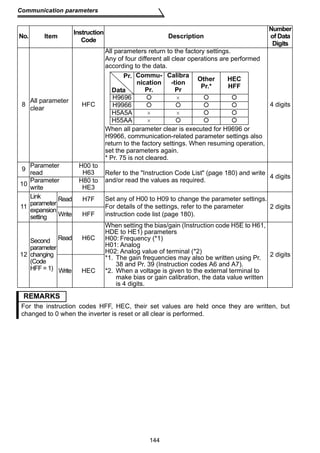
![Computer
Inverter
Inverter
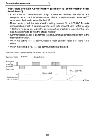
Computer
Inverter data processing time
= waiting time + data check time
(setting 10ms) (12ms)
REMARKS
When communication parameter n7 waiting time setting ≠ - - -, create the communication
request data without waiting time in the data format. (The number of characters is
decremented by 1.)
Data sending time
(refer to the following formula)
Computer
Inverter
Inverter
Computer
Inverter data processing time = waiting time + data check time
(set value 10ms) (12ms)
ACK ENQ
10ms or
more required
10ms or
more required
STX
Data sending time
(refer to the following formula)
Data sending time
(refer to the following formula)
Computer
Inverter
Inverter
Computer
Inverter data processing time = waiting time + data check time
(set value 10ms) (12ms)
ENQ
10ms or
more required
Data sending time
(refer to the following formula)
Communication speed = Data sending time (s)
(Refer to page 135) ×
Communication specification
137
Communication parameters
2
FUNCTIONS
5) Waiting time
Specify the waiting time between the receipt of data at the inverter from the
computer and the transmission of reply data. Set the waiting time in accordance
with the response time of the computer between 0 and 150ms in 10ms increments
(e.g. 1 = 10ms, 2 = 20ms).
6) Response time
[Formula for data sending time]
1
× Number of data characters
(bps)
Communication specification
(Total number of bits)
(See below)
Name Number of Bits
Stop bit length 1 bit
2 bits
Data length 7 bits
8 bits
Parity check
Yes 1 bit
No 0 bit
In addition to the bits in the above table, 1 bit is required for the start bit.
Minimum total number of bits ... 9 bits
Maximum total number of bits ... 12 bits](https://image.slidesharecdn.com/mitsubishi-s500e-vfd-detailed-manual-140830020319-phpapp02/85/Mitsubishi-s500-e-vfd-detailed-147-320.jpg)
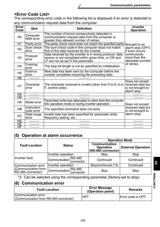
![141
Communication parameters
2
FUNCTIONS
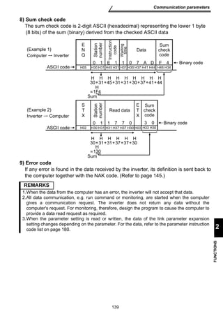
Setting items and set data
After completion of parameter settings, set the instruction codes and data then start
communication from the computer to allow various types of operation control and
monitoring.
No. Item Instruction
Code Description
Number
of Data
Digits
1 Operation
mode
Read H7B
H0000: Communication operation
H0001: External operation
H0002: PU operation 4 digits
Write HFB H0000: Communication operation
H0001: External operation
2
Monitoring
Output
frequency
[speed]
H6F
H0000 to HFFFF: Output frequency in 0.01Hz
increments
Pr. 37 = 0 (factory setting) H0000 to HFFFF: Speed in 1r/min increments 4 digits
When Pr. 37 = 0.1 to 999, expansion link parameter (HFF)
= 0
H000000 to HFFFFFF: Speed in 0.01r/min increments
When Pr. 37 = 0.1 to 999, expansion link parameter (HFF)
6 digits
= 1
Output
current H70 H0000 to HFFFF: Output current (hexadecimal) in 0.01A
increments 4 digits
Alarm
definition H74 to H75
H0000 to HFFFF: Two most recent alarm definitions
Alarm definition display example (instruction code H74)
* Error code may not be returned.
4 digits
b15 b8b7 b0
0 0 1 1 0 0 0 0 1 0 1 0 0 0 0 0
Previous alarm
(H30)
Most recent alarm
(HA0)
Alarm data
Data Description Data Description
H00 No alarm H60 OLT
H10 OC1 H70 BE
H11 OC2 H80 GF
H12 OC3 H90 OHT
H20 OV1 HA0 OPT
H21 OV2 HB0 PE
H22 OV3 HB1 PUE
H30 THT HB2 RET
H31 THM HC0 CPU*
H40 FIN](https://image.slidesharecdn.com/mitsubishi-s500e-vfd-detailed-manual-140830020319-phpapp02/85/Mitsubishi-s500-e-vfd-detailed-151-320.jpg)
![142
Communication parameters
3 Run
command HFA
* Function change can be made using Pr. 60 to Pr. 63
(input terminal function selection).
2 digits
4 Inverter status
monitor H7A
* Function change can be made using Pr. 64 and Pr. 65
(output terminal function selection).
2 digits
No. Item Instruction
Code Description
Number
of Data
Digits
b0 :
b1 : Forward
rotation (STF)
b2 : Reverse
rotation (STR) *
b3 : Low speed (RL) *
b4 : Middle speed (RM) *
b5 : High speed (RH) *
b6 :
b7 :
b7
0 0 0 0 0 0 1 0
b0
[For example 1]
[Example 1] H02 ... Forward
rotation
[Example 2] H00 ... Stop
b7
0 0 0 0 0 0 1 0
b0
[For example 1]
[Example 1] H02 ... During
forward
rotation
[Example 2] H80 ... Stop due to
alarm
b0: Inverter
running (RUN)*
b1: Forward rotation
b2: Reverse rotation
b3: Up to
frequency (SU)
b4: Overload (OL)
b5:
b6: Frequency
detection (FU)
b7: Alarm occurrence*](https://image.slidesharecdn.com/mitsubishi-s500e-vfd-detailed-manual-140830020319-phpapp02/85/Mitsubishi-s500-e-vfd-detailed-152-320.jpg)
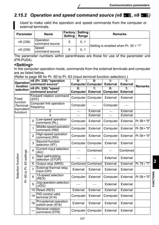
![n8 (Pr. 338) operation
command source
0:
Computer
External n9 (Pr. 339) speed
Remarks command source
0:
Computer
1:
External
1:
0:
Computer
1:
External
0:
Computer
1:
External
Remote setting
(RH, RM, RL) Computer External Computer External
15-speed selection (REX) 1, 2
PU operation interlock
(MRS) External External External External Pr. 79 = 7
Operation
location
selection
When Pr. 79 operation mode selection is set to 7 (PU operation interlock
function), only the external terminal is made valid independently of the n8 and
n9 settings because the MRS terminal is shared.
The operation mode at power on and at power restoration after instantaneous
power failure can be selected.
Set 1 in n10 to select the computer link operation mode.
After a link start, parameter write is enabled with a program.
Setting
Range Remarks
mode selection 0 0, 1 Setting is enabled when Pr. 30 = 1
148
Communication parameters
RH, RM,
RL, REX
selection
function
Pr. 59 =
MRS
selection
function
[Explanation of table]
External : Operation is valid only from external terminal signal.
Computer : Operation is valid only from computer.
Combined : Operation is valid from either of external terminal and computer.
: Operation is invalid from either of external terminal and computer.
CAUTION
2.15.3 Link startup mode selection (n10 )
Parameter Name Factory
Setting
n10 (340) Link startup
The parameter number in parentheses is the one for use with the parameter unit (FR-PU04).](https://image.slidesharecdn.com/mitsubishi-s500e-vfd-detailed-manual-140830020319-phpapp02/85/Mitsubishi-s500-e-vfd-detailed-158-320.jpg)