Download to read offline


![81
MODBUS communication
CRC Generation (continued):
Pseudo code for generating a CRC-16:
CONST ARRAY BUFFER /* data,ex: 11h, 03h, 00h,6bh,00h,02h */
CONST WORD POLYNOMIAL = 0a001h /* X16 = X15 + X2 + X1 */
/* SUBROTINUE OF CRC CACULATE START */
CRC_CAL(LENGTH)
VAR INTEGER LENGTH;
{
VAR WORD CRC16 = 0FFFFH ; /* CRC16 initialize */
VAR INTEGER = I,j; /* LOOP COUNTER */
VAR BYTE DATA; /* DATA BUFFER */
FOR (I=1;I=LENGTH;I++) /* BYTE LOOP */
{
DATA == BUFFER[I];
CRC16 == CRC16 XOR DATA;
FOR (J=1;J=8;J++) /* BIT LOOP */
{
IF ((DATA XOR CRC16) AND 0001H) = 1 THEN
CRC16 = (CRC16 SHR 1) XOR POLYNOMIAL;
ELSE
CRC16 == CRC16 SHR 1;
DATA == DATA SHR 1;
};
};
};](https://image.slidesharecdn.com/ct2000evmanualenglishversion1-140613213458-phpapp02/85/Ct2000-ev-manual_english_version-1-1-81-320.jpg)


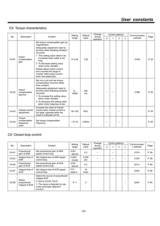


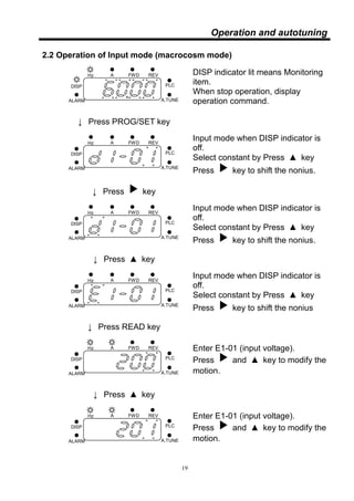
This document provides instructions for installing and operating an inverter. It includes wiring diagrams, terminal specifications, installation guidelines, and descriptions of operation modes and functions. Chapters cover installation, operation and autotuning, settings, control modes, protective functions, specifications, and more. The document aims to ensure proper use of the inverter.


![Ct2000 es manual_english_version_1[1].0](https://cdn.slidesharecdn.com/ss_thumbnails/ct2000esmanualenglishversion11-140613213448-phpapp01-thumbnail.jpg?width=640&height=640&fit=bounds)

![Ct2000 pro plus_manual_english[1]](https://cdn.slidesharecdn.com/ss_thumbnails/ct2000proplusmanualenglish1-140613213527-phpapp02-thumbnail.jpg?width=640&height=640&fit=bounds)


