Download to read offline

![Chapter 1 Introduction|
Revision Oct. 2009, 07EE, SW--PW V1.14/CTL V2.14 1-13
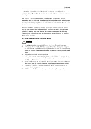
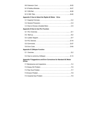
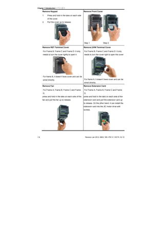
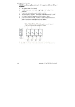
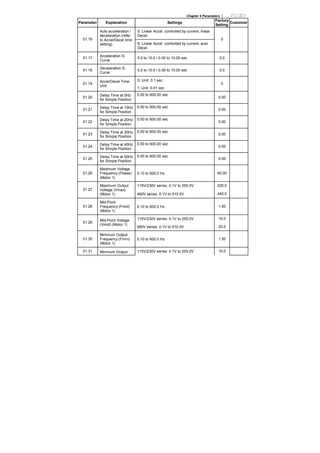
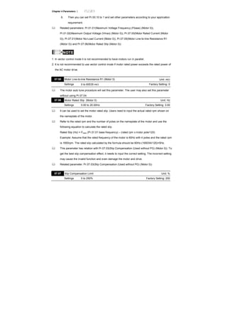
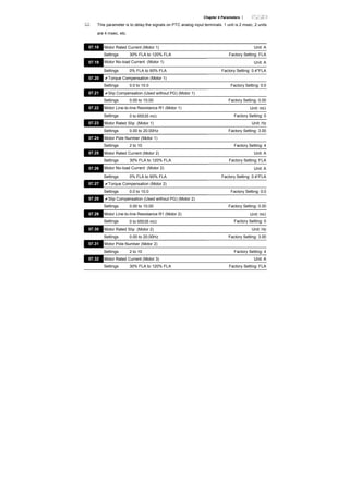
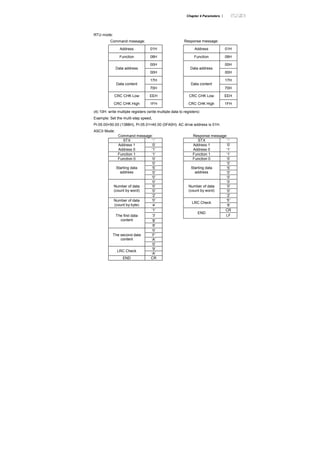
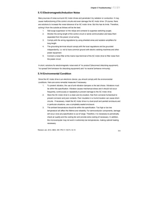
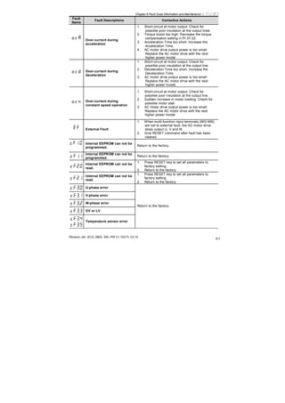
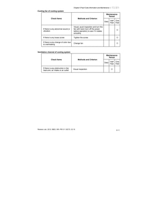
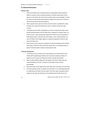
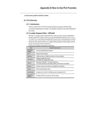
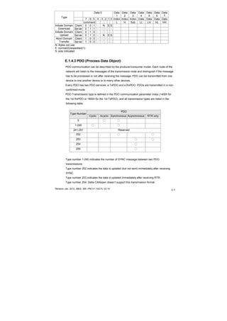
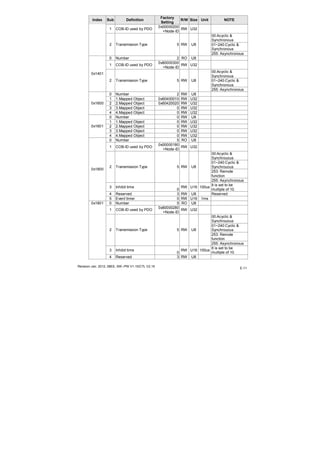
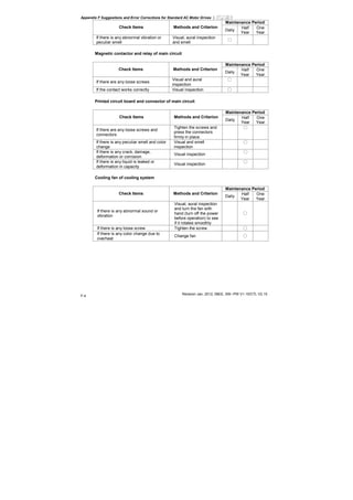
1.3 Dimensions
(Dimensions are in millimeter and [inch])
Frame A
D
H1
H
W
W1
S2S1
D1
D2
Unit: mm [inch]
Frame W W1 H H1 D D1 D2 S1 S2
A (A1)
72.0
[2.83]
60.0
[2.36]
142.0
[5.59]
120.0
[4.72]
152.0
[5.98]
50.0
[1.97]
4.5
[0.18]
5.2
[0.20]
5.2
[0.20]
A (A2)
72.0
[2.83]
56.0
[2.20]
155.0
[6.10]
143.0
[5.63]
111.5
[4.39]
9.5
[0.37]
- 5.3
[0.21]
-
NOTE
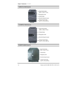
Frame A (A1): VFD002E11A/21A/23A, VFD004E11A/21A/23A/43A, VFD007E21A/23A/43A,
VFD015E23A/43A, VFD002E11C/21C/23C, VFD004E11C/21C/23C/43C, VFD007E21C/23C/43C,
VFD015E23C/43C, VFD002E11T/21T/23T, VFD004E11T/21T/23T/43T, VFD007E21T/23T/43T,
VFD015E23T/43T
Frame A (A2): VFD002E11P/21P/23P, VFD004E11P/21P/23P/43P, VFD007E21P/23P/43P,
VFD015E23P/43P](https://image.slidesharecdn.com/vfd-emen20120118-140613014256-phpapp01/85/Vfd-e-m-en_20120118-22-320.jpg)
![Chapter 1 Introduction|
1-14 Revision Jan 2012, 08EE, SW--PW V1.15/CTL V2.15
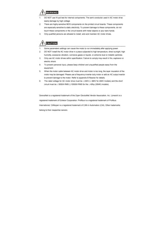
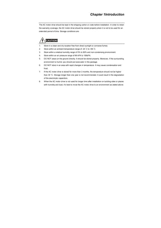
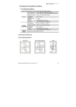
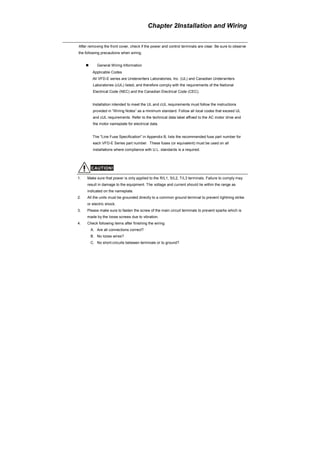
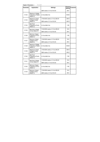
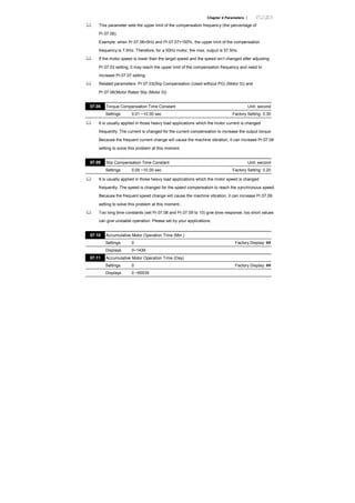
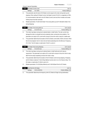
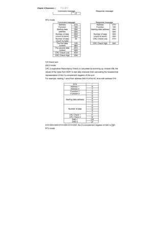
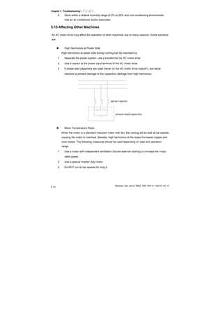
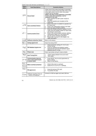
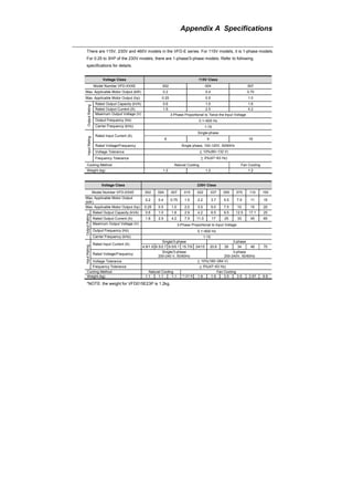
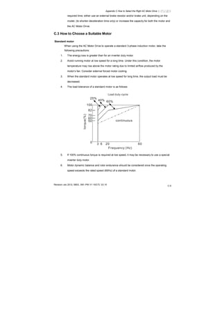
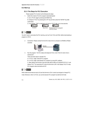
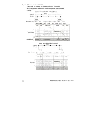
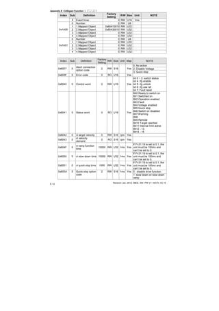
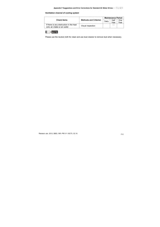
Frame B
D
H
S2
H1
W
W1
D1
D2
S1
Unit: mm [inch]
Frame W W1 H H1 D D1 D2 S1 S2
B1
100.0
[3.94]
89.0
[3.50]
174.0
[6.86]
162.0
[6.38]
152.0
[5.98]
50.0
[1.97]
4.0
[0.16]
5.5
[0.22]
5.5
[0.22]
NOTE
Frame B (B1): VFD007E11A, VFD015E21A, VFD022E21A/23A/43A, VFD037E23A/43A,
VFD007E11C, VFD015E21C, VFD022E21C/23C/43C, VFD037E23C/43C](https://image.slidesharecdn.com/vfd-emen20120118-140613014256-phpapp01/85/Vfd-e-m-en_20120118-23-320.jpg)
![Chapter 1 Introduction|
Revision Oct. 2009, 07EE, SW--PW V1.14/CTL V2.14 1-15
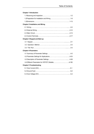
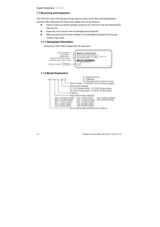
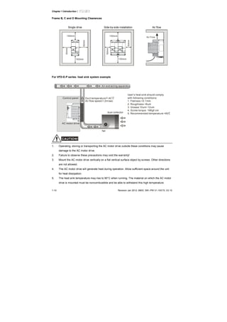
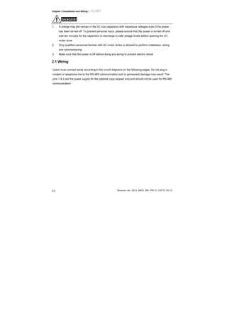
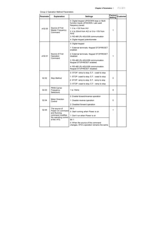
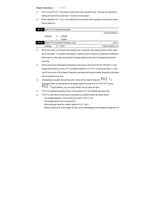
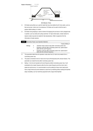
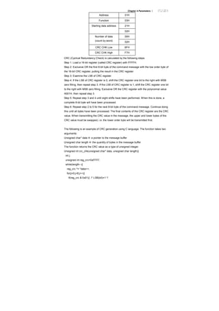
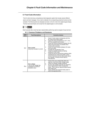
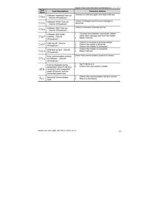
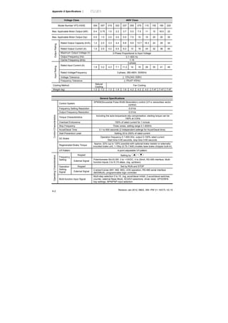
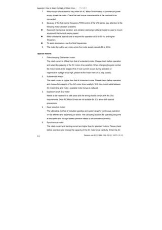
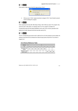
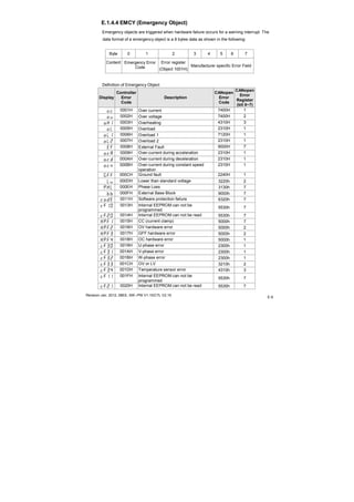
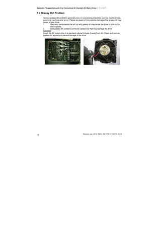
Frame C
H
H1
W1
W
S1
S2
D
D1
D2
Unit: mm [inch]
Frame W W1 H H1 D D1 D2 S1 S2
C1
130.0
[5.12]
116.0
[4.57]
260.0
[10.24]
246.5
[9.70]
169.2
[6.66]
78.5
[3.09]
8.0
[0.31]
6.5
[0.26]
5.5
[0.22]
NOTE
Frame C (C1): VFD055E23A/43A, VFD075E23A/43A, VFD110E23A/43A, VFD055E23C/43C,
VFD075E23C/43C, VFD110E23C/43C](https://image.slidesharecdn.com/vfd-emen20120118-140613014256-phpapp01/85/Vfd-e-m-en_20120118-24-320.jpg)
![Chapter 1 Introduction|
1-16 Revision Jan 2012, 08EE, SW--PW V1.15/CTL V2.15
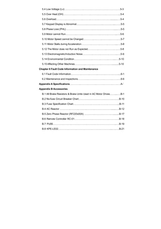
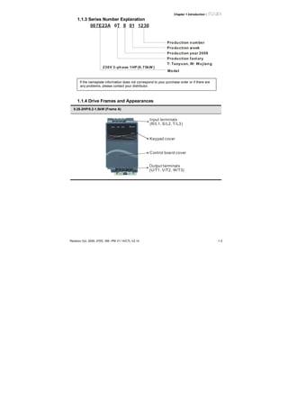
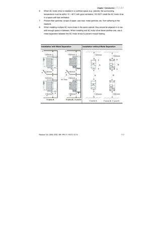
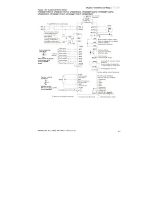
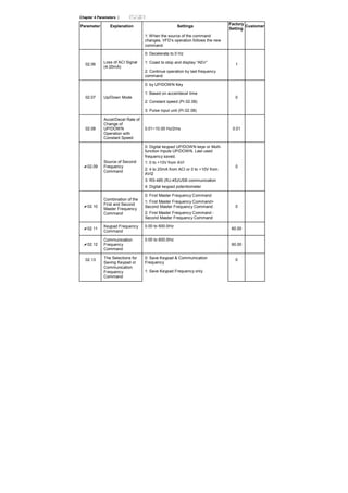
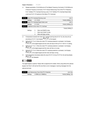
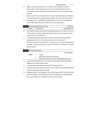
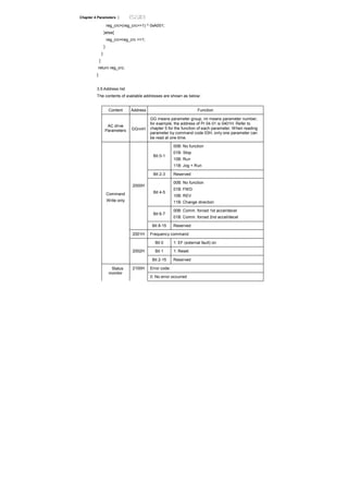
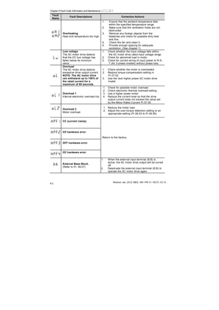
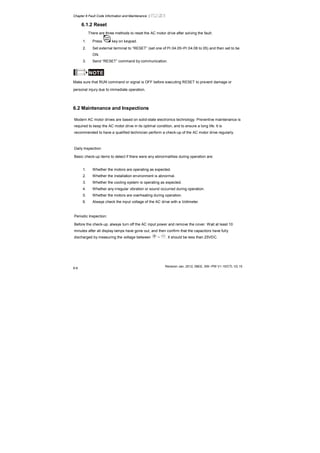
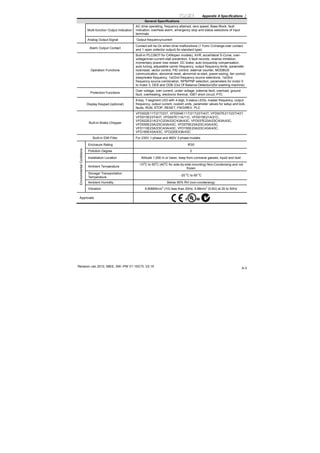
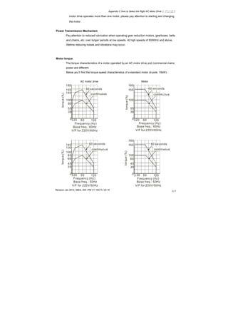
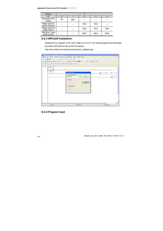
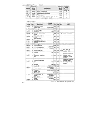
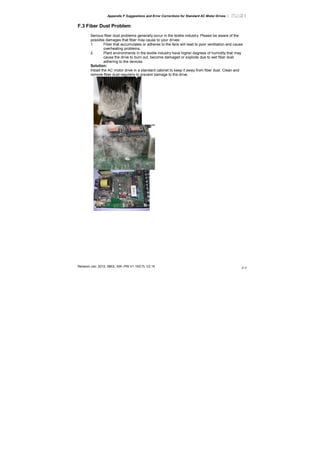
Frame D
W1
W
D2
D1
D
H1
H
S1
S2
Unit: mm [inch]
Frame W W1 H H1 D D1 D2 S1 S2
D
200.0
[7.87]
180.0
[7.09]
310.0
[12.20]
290.0
[11.42]
190.0
[7.48]
92.0
[3.62]
10.0
[0.39]
10.0
[0.39]
9.0
[0.35]
NOTE
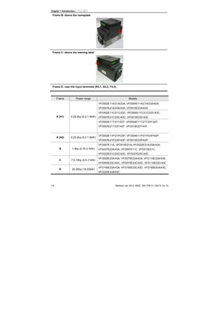
Frame D (D1): VFD150E23A/23C, VFD150E43A/43C, VFD185E43A/43C, VFD220E43A/43C,](https://image.slidesharecdn.com/vfd-emen20120118-140613014256-phpapp01/85/Vfd-e-m-en_20120118-25-320.jpg)
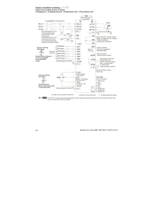
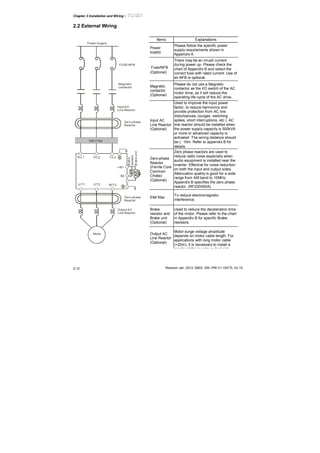
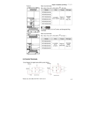
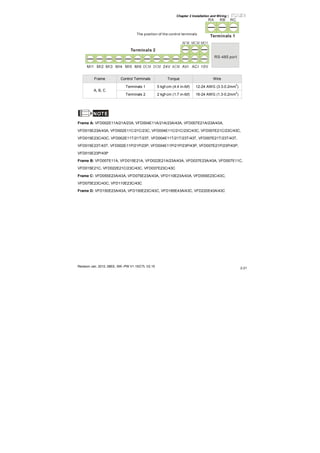
![Chapter 2 Installation and Wiring|
Revision Jan. 2012, 08EE, SW--PW V1.15/CTL V2.15
2-15
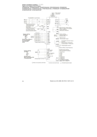
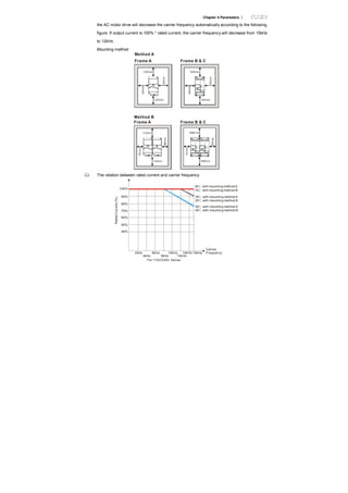
to the group 9 for details. Method2, control by the optional keypad KPE-LE02. Refer to
Appendix B for details.
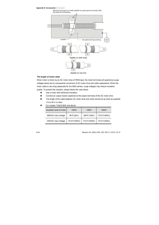
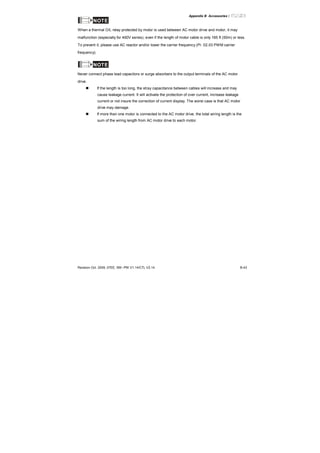
When it needs to install the filter at the output side of terminals U/T1, V/T2, W/T3 on the
AC motor drive. Please use inductance filter. Do not use phase-compensation capacitors
or L-C (Inductance-Capacitance) or R-C (Resistance-Capacitance), unless approved by
Delta.
DO NOT connect phase-compensation capacitors or surge absorbers at the output
terminals of AC motor drives.
Use well-insulated motor, suitable for inverter operation.
Terminals [+/B1, B2] for connecting brake resistor
BR
B2
BR
+/B1 B2
BR
B1 -
BUE
+/B1
Brakeresistor (optional)
Brake unit(optional)
Refer to Appendix B for details.
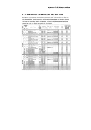
Connect a brake resistor or brake unit in applications with frequent deceleration ramps,
short deceleration time, too low brake torque or requiring increased brake torque.
If the AC motor drive has a built-in brake chopper (frame B, frame C and VFDxxxExxT
models), connect the external brake resistor to the terminals [+/B1, B2] or [B1, B2].
Models of frame A don’t have a built-in brake chopper. Please connect an external
optional brake unit (BUE-series) and brake resistor. Refer to BUE series user manual for
details.
Connect the terminals [+(P), -(N)] of the brake unit to the AC motor drive terminals [+/B1, -
]. The length of wiring should be less than 5m with cable.
When not used, please leave the terminals [+/B1, -] open.
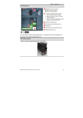
WARNING!
Short-circuiting [B2] or [-] to [+/B1] can damage the AC motor drive.](https://image.slidesharecdn.com/vfd-emen20120118-140613014256-phpapp01/85/Vfd-e-m-en_20120118-40-320.jpg)
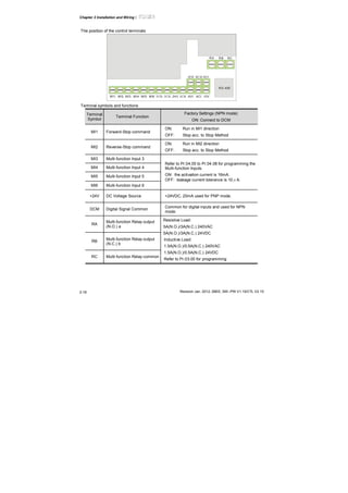
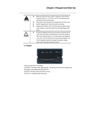

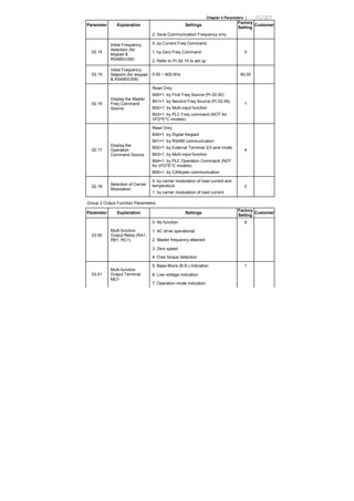
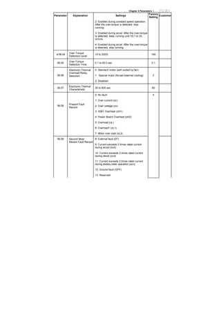

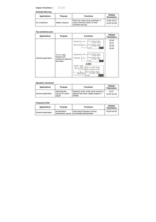

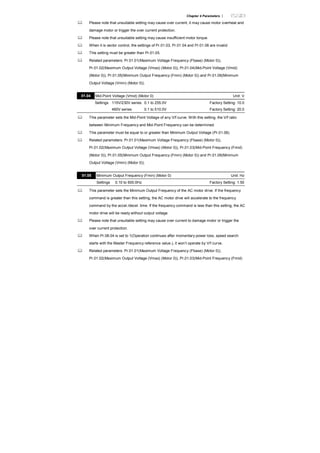
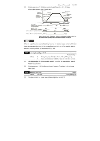

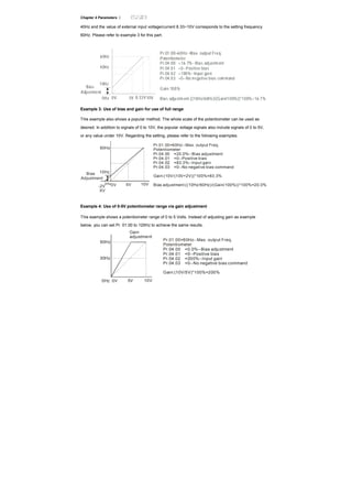

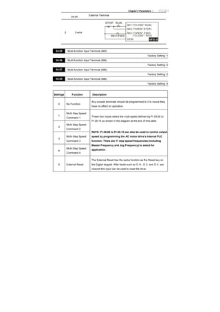

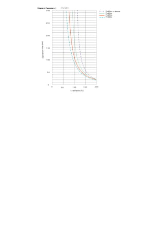


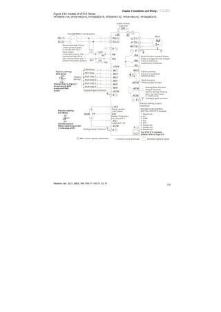
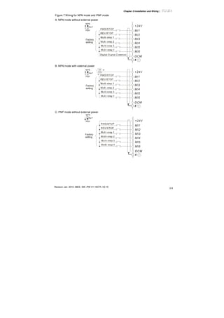
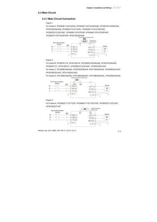
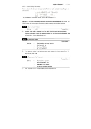
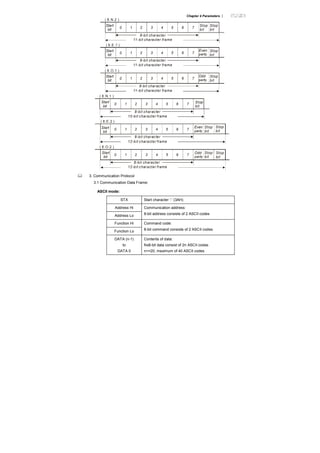
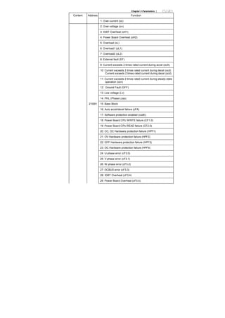
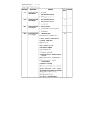
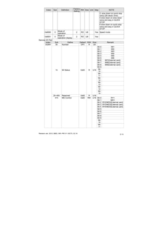
![Chapter 4 Parameters |
AVI
ACM
+10V
PTC
VFD-E
47kΩ
resistor-divider
R1
internal circuit
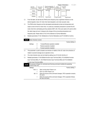
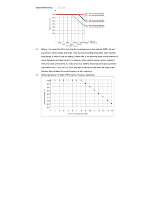
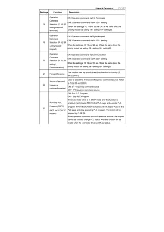
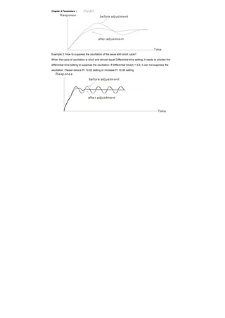
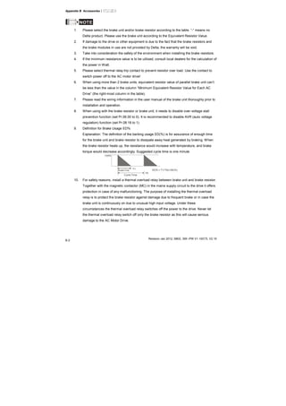
Refer to following calculation for protection level and warning level.
Protection level
Pr.07.14= V+10 * (RPTC1//47K) / [R1+( RPTC1//47K)]
Warning level
Pr.07.16= V+10 * (RPTC2//47K) / [R1+( RPTC2//47K)]
Definition:
V+10: voltage between +10V-ACM, Range 10.4~11.2VDC
RPTC1: motor PTC overheat protection level. Corresponding voltage level set in Pr.07.14,
RPTC2: motor PTC overheat warning level. Corresponding voltage level set in Pr.07.15,
47kΩ: is AVI input impedance, R1: resistor-divider (recommended value: 1~20kΩ)
Take the standard PTC thermistor as example: if protection level is 1330Ω, the voltage
between +10V-ACM is 10.5V and resistor-divider R1 is 4.4kΩ. Refer to following calculation
for Pr.07.14 setting.
1330//47000=(1330*47000)/(1330+47000)=1293.4
10.5*1293.4/(4400+1293.4)=2.38(V) ≒2.4(V)
Therefore, Pr.07.14 should be set to 2.4.
550
1330
temperature ( )℃
resistor value ( )Ω
Tr
Tr-5℃ Tr+5℃](https://image.slidesharecdn.com/vfd-emen20120118-140613014256-phpapp01/85/Vfd-e-m-en_20120118-173-320.jpg)


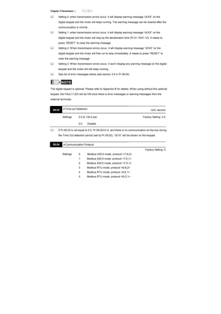
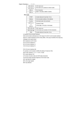
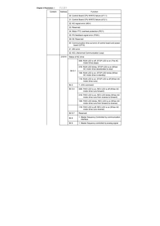
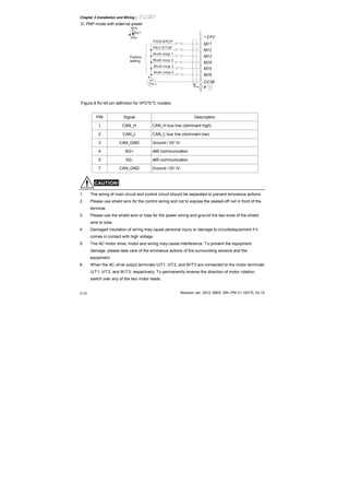
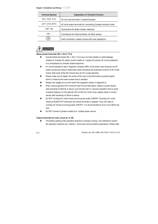
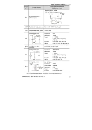
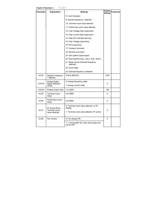
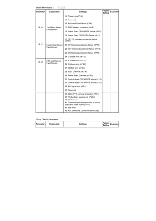
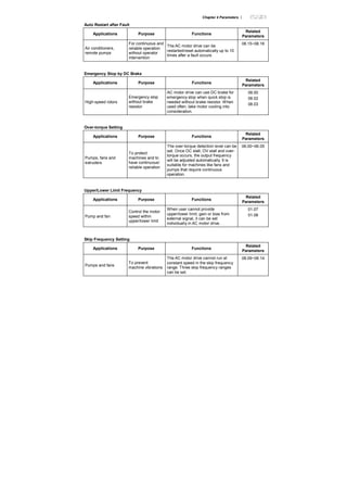
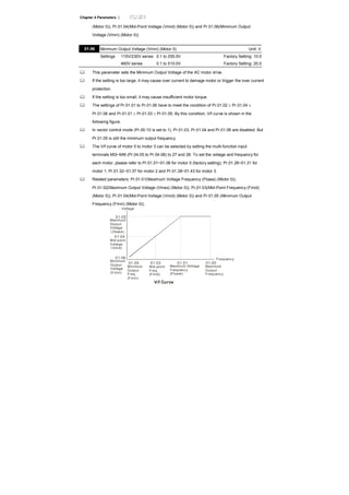
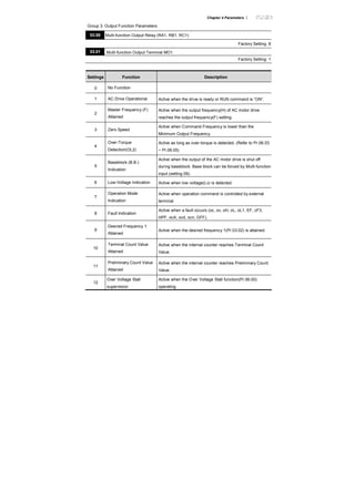
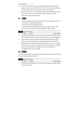
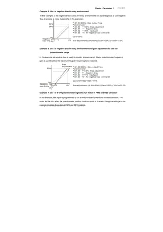
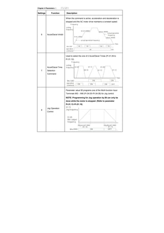
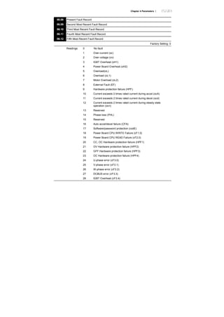
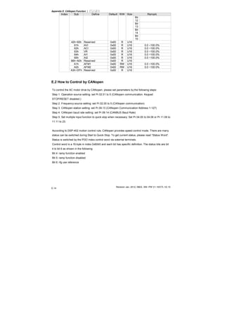
![Chapter 4 Parameters |
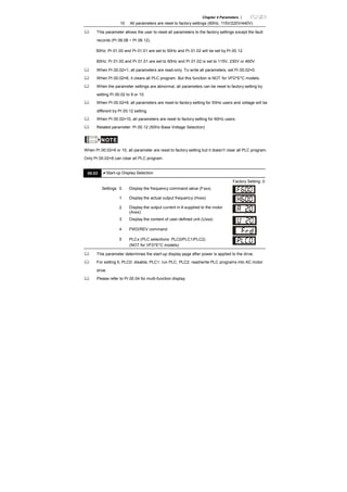
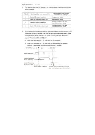
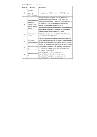
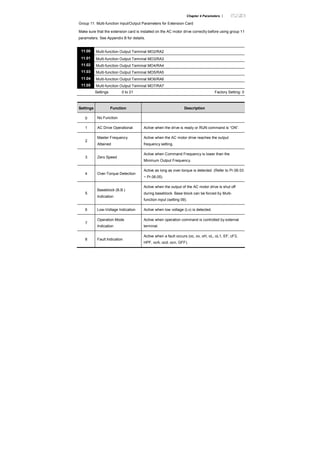
#include<conio.h>
#include<process.h>
#define PORT 0x03F8 /* the address of COM1 */
/* the address offset value relative to COM1 */
#define THR 0x0000
#define RDR 0x0000
#define BRDL 0x0000
#define IER 0x0001
#define BRDH 0x0001
#define LCR 0x0003
#define MCR 0x0004
#define LSR 0x0005
#define MSR 0x0006
unsigned char rdat[60];
/* read 2 data from address 2102H of AC drive with address 1 */
unsigned char tdat[60]={':','0','1','0','3','2','1','0',’2', '0','0','0','2','D','7','r','n'};
void main(){
int i;
outportb(PORT+MCR,0x08); /* interrupt enable */
outportb(PORT+IER,0x01); /* interrupt as data in */
outportb(PORT+LCR,(inportb(PORT+LCR) | 0x80));
/* the BRDL/BRDH can be access as LCR.b7==1 */
outportb(PORT+BRDL,12); /* set baudrate=9600, 12=115200/9600*/
outportb(PORT+BRDH,0x00);
outportb(PORT+LCR,0x06); /* set protocol, <7,N,2>=06H, <7,E,1>=1AH,
<7,O,1>=0AH, <8,N,2>=07H, <8,E,1>=1BH, <8,O,1>=0BH */
for(i=0;i<=16;i++){
while(!(inportb(PORT+LSR) & 0x20)); /* wait until THR empty */
outportb(PORT+THR,tdat[i]); /* send data to THR */ }
i=0;
while(!kbhit()){
if(inportb(PORT+LSR) & 0x01){ /* b0==1, read data ready */
rdat[i++]=inportb(PORT+RDR); /* read data form RDR */
} } }
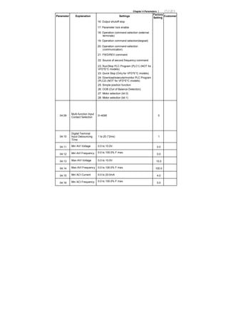
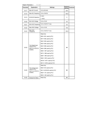
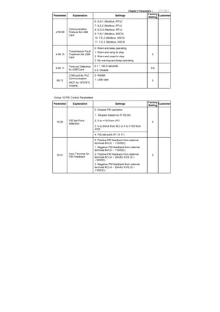
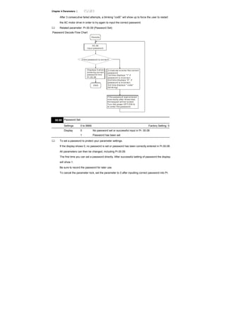
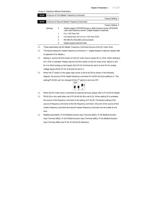
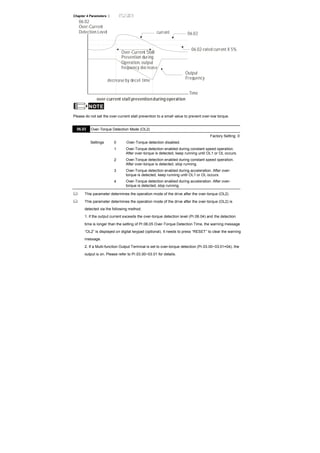
09.05 Reserved](https://image.slidesharecdn.com/vfd-emen20120118-140613014256-phpapp01/85/Vfd-e-m-en_20120118-205-320.jpg)

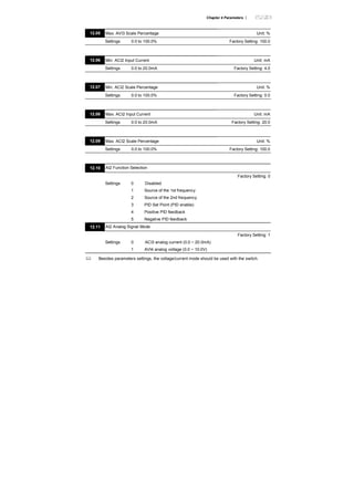
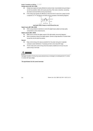
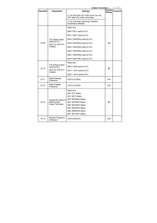
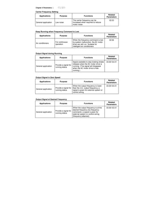
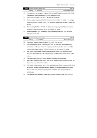
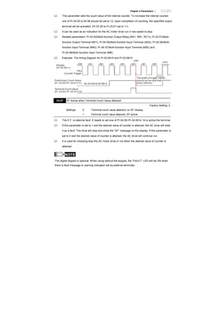
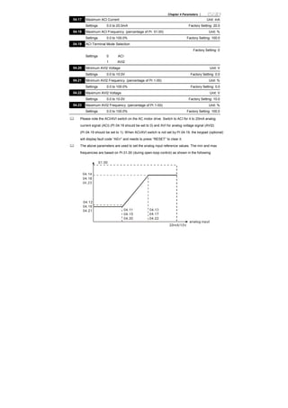
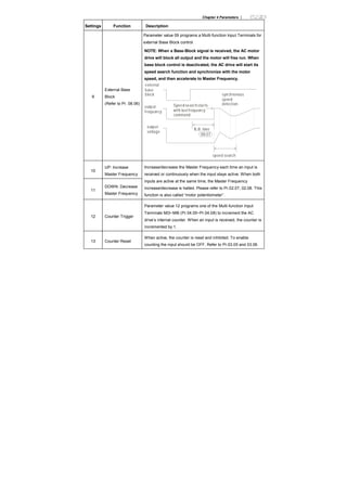
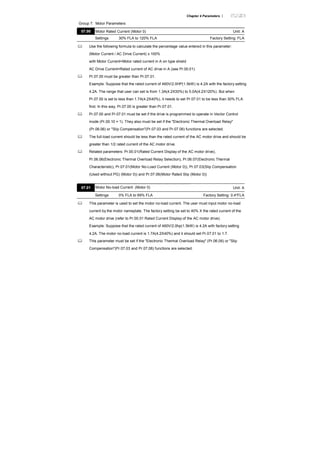
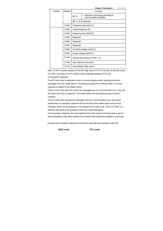
![Chapter 4 Parameters |
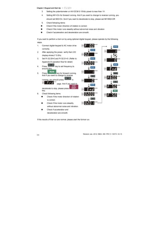
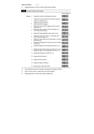
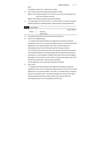
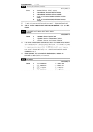
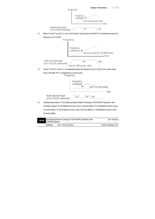
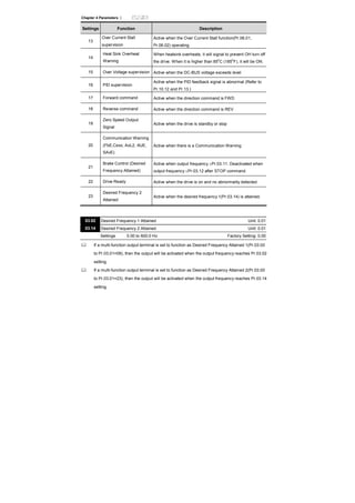
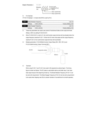
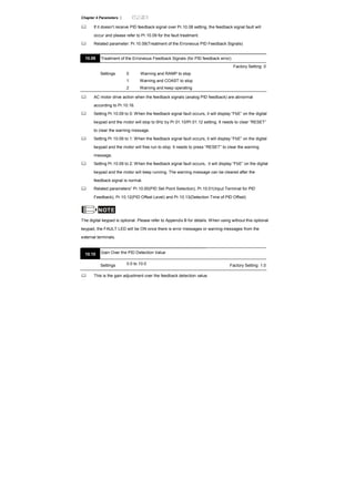
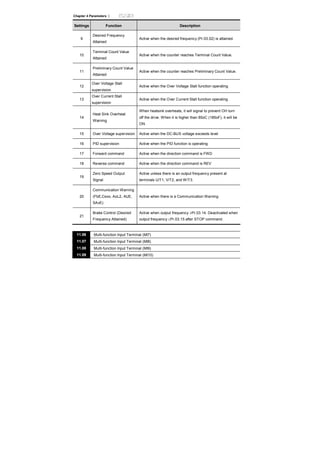
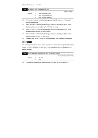
NOTE
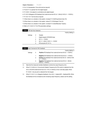
If the scale of the voltmeter is less than 10V, refer to following formula to set Pr.12.22:
Pr.12.22 = [(full scale voltage)/10]*100%.
Example: When using voltmeter with full scale (5V), Pr.12.22 should be set to 5/10*100%=50%. If
Pr.12.21 is set to 0, the output voltage will correspond to the max. output frequency.
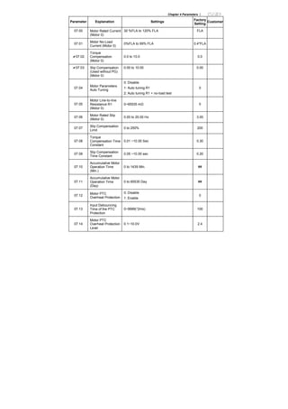
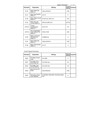
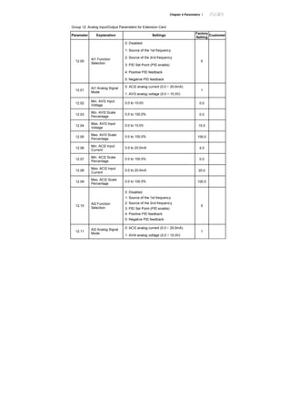
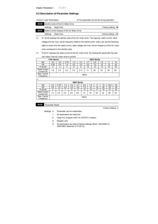
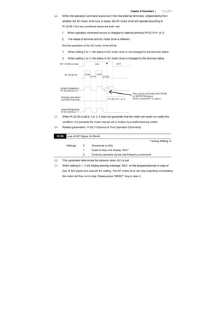
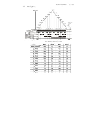
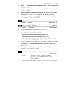
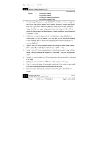
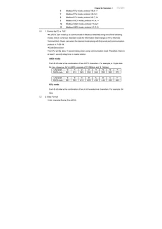
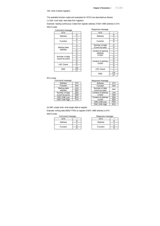
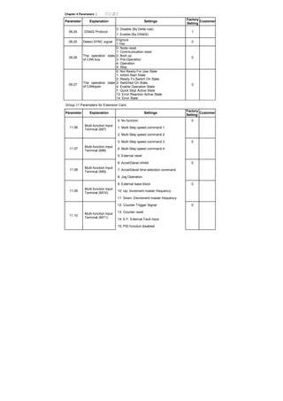
12.23 AO2Terminal Analog Signal Mode
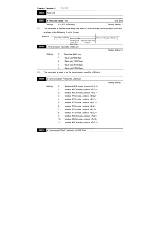
Factory Setting: 0
Settings 0 AVO2
1 ACO2 (analog current 0.0 to 20.0mA)
2 ACO2 (analog current 4.0 to 20.0mA)
Besides parameter setting, the voltage/current mode should be used with the switch.
AVI3
ACI2
AVI4
ACI3
AVO1
ACO1
AVO2
ACO2
12.24 AO2 Analog Output Signal
Factory Setting: 0
Settings 0 Analog Frequency
1 Analog Current (0 to 250% rated current)
12.25 AO2 Analog Output Gain Unit: %
Settings 1 to 200% Factory Setting: 100
Setting method for the AO2 is the same as the AO1.
12.26 AUI Analog Input Selection
Factory Setting: 0
Settings 0 No function
1 Source of the 1st frequency
2 Source of the 2nd frequency](https://image.slidesharecdn.com/vfd-emen20120118-140613014256-phpapp01/85/Vfd-e-m-en_20120118-226-320.jpg)
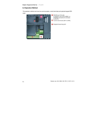
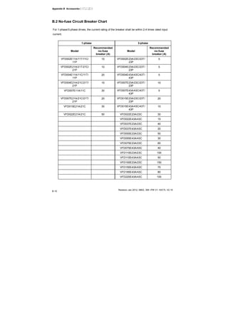
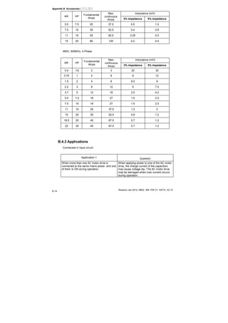
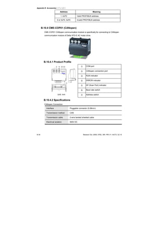
![Appendix B Accessories|
Revision Jan 2012, 08EE, SW--PW V1.15/CTL V2.15
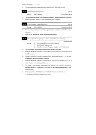
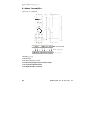
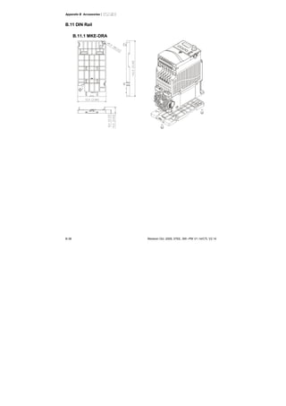
B-8
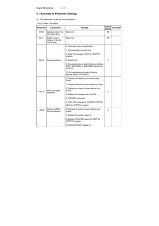
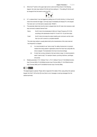
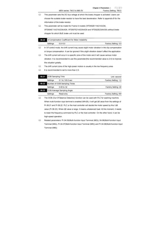
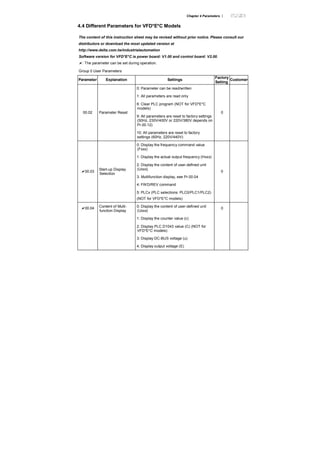
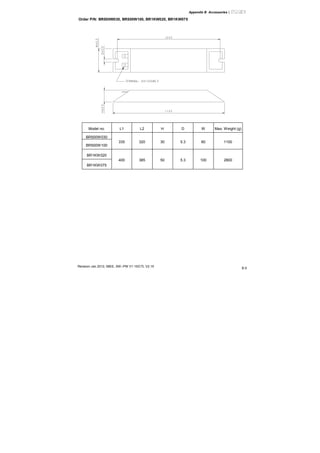
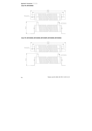
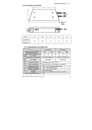
B.1.3 Dimensions for Brake Unit
(Dimensions are in millimeter[inch])](https://image.slidesharecdn.com/vfd-emen20120118-140613014256-phpapp01/85/Vfd-e-m-en_20120118-271-320.jpg)
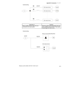
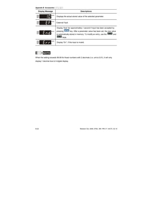
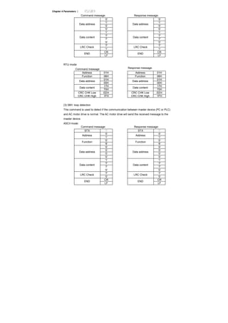
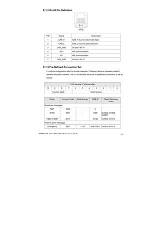
![Appendix B Accessories|
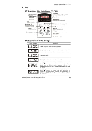
B-24 Revision Oct. 2009, 07EE, SW--PW V1.14/CTL V2.14
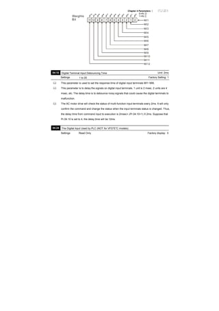
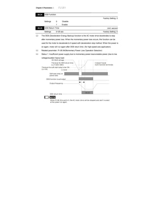
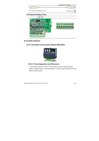
B.8.3 Reference Table for the 7-segment LED Display of the Digital
Keypad
Digit 0 1 2 3 4 5 6 7 8 9
LED
Display
English
alphabet
A a B C c D d E e F
LED
Display
- - - -
English
alphabet
f G g H h I i J j K
LED
Display
- -
English
alphabet
k L l M m N n O o P
LED
Display
- - - -
English
alphabet
p Q q R r S s T t U
LED
Display
- - - -
English
alphabet
u V v W w X x Y y Z
LED
Display
- - - - - - -
English
alphabet
z
LED
Display
-
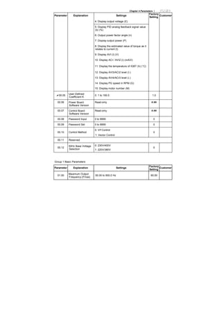
B.8.4 Keypad Dimensions
(Dimensions are in millimeter[inch])
71.9 [2.83]
42.4[1.67]
1.5 [0.06]16.3 [0.64]
52.4 [2.06]8.6 [0.34]
61.0 [2.40]
34.3[1.35]
8.1[0.32]
25.9 [1.02]
M3*0.5(2X)](https://image.slidesharecdn.com/vfd-emen20120118-140613014256-phpapp01/85/Vfd-e-m-en_20120118-287-320.jpg)
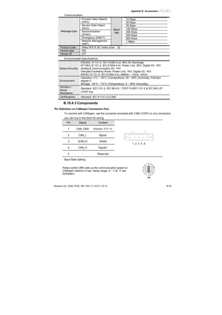
![Appendix B Accessories|
B-28 Revision Oct. 2009, 07EE, SW--PW V1.14/CTL V2.14
72.2 [2.84]
57.3[2.26]
14.3[0.57]
59.7[2.35]
3.5 [0.14]35.8 [1.41]
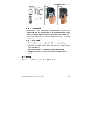
CME-DN01
AD D1 AD D2
SP
500K
250K
125K
BAUD
M ODNET
UNIT: mm(inch)
1
543
2
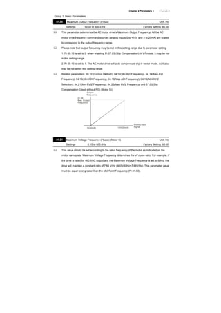
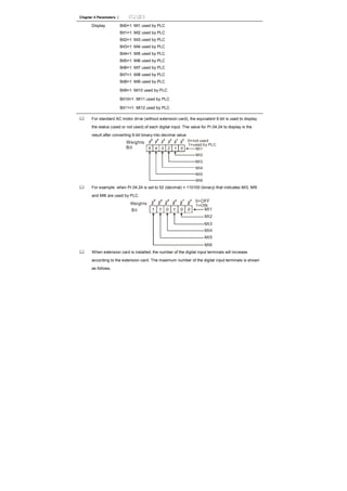
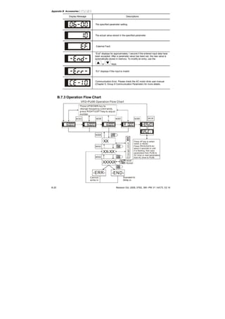
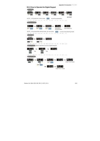
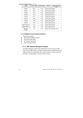
B.10.1.2 Wiring and Settings
Refer to following diagram for details.
CME-DN01
ADD1 ADD2
SP
500K
250K
125K
BAUD
MODNET
MAC address Date Rate
CAN-LV+ Empty
Pin
CAN-H V-
1: Reserved
2: EV
5: SG+
6: Reserved
7: Reserved
8: Reserved
3: GND
4: SG-
Setting baud rate
BAUD
0
Switch
Value
Baud
Rate
0 125K
1 250K
2 500K
Other AUTO
Setting MAC addresses:
use decimal system.
ADD1 ADD2
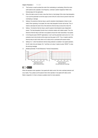
B.10.1.3 Mounting Method
Step1 and step2 show how to mount this communication module onto VFD-E. The
dimension on the left hand side is for your reference.](https://image.slidesharecdn.com/vfd-emen20120118-140613014256-phpapp01/85/Vfd-e-m-en_20120118-291-320.jpg)
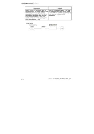
![Appendix B Accessories|
B-30 Revision Oct. 2009, 07EE, SW--PW V1.14/CTL V2.14
B.10.2 LonWorks Communication Module (CME-LW01)
B.10.2.1 Introduction
Device CME-LW01 is used for communication interface between Modbus and LonTalk.
CME-LW01 needs be configured via LonWorks network tool first, so that it can perform the
function on LonWorks network. No need to set CME-LW01 address.
This manual provides instructions for the installation and setup for CME-LW01 that is used
to communicate with Delta VFD-E (firmware version of VFD-E should conform with CME-
LW01 according to the table below) via LonWorks Network.
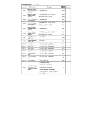
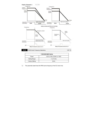
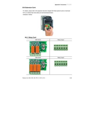
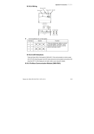
B.10.2.2 Dimensions
57.3[2.26]
72.2 [2.84]
59.7[2.35]
9.5[0.37]
3.5 [0.14]34.8 [1.37]
S P
CM E-LW01
B.10.2.3 Specifications
Power supply: 16-30VDC, 750mW
Communication: Modbus in ASCII format, protocol: 9600, 7, N, 2
LonTalk: free topology with FTT-10A 78 Kbps.
LonTalk terminal: 4-pin terminals, wire gauge: 28-12 AWG, wire strip length: 7-8mm
RS-485 port: 8 pins with RJ-45](https://image.slidesharecdn.com/vfd-emen20120118-140613014256-phpapp01/85/Vfd-e-m-en_20120118-293-320.jpg)
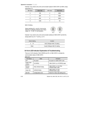
![Appendix B Accessories|
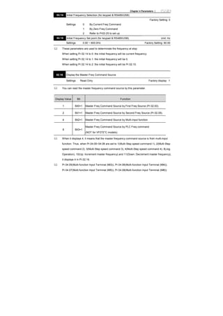
Revision Oct. 2009, 07EE, SW--PW V1.14/CTL V2.14 B-33
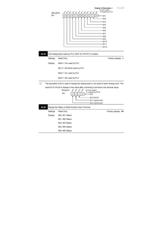
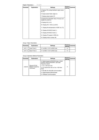
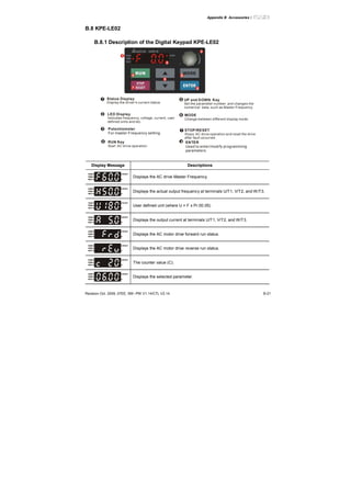
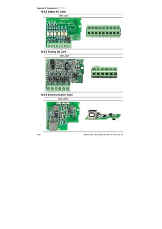
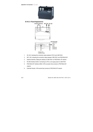
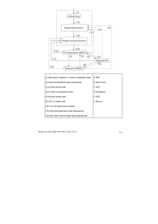
B.10.3.2 Dimensions
57.3[2.26]
59.7[2.35]
3.6[0.14]
72.2 [2.84]
34.8 [1.37]
ADDH ADDL
SPNET
CME-P B01
UNIT: mm(inch)
B.10.3.3 Parameters Settings in VFD-E
VFD-E
Baud Rate 9600 Pr.09.01=1
RTU 8, N, 2 Pr.09.04=3
Freq. Source Pr.02.00=4
Command Source Pr.02.01=3
B.10.3.4 Power Supply
The power of CME-PD01 is supplied from VFD-E. Please connect VFD-E to CME-PD01 by
using 8 pins RJ-45 cable, which is packed together with CME-PD01. After connection is
completed, CME-PD01 is powered whenever power is applied to VFD-E.
B.10.3.5 PROFIBUS Address
CME-PD01 has two rotary switches for the user to select the PROFIBUS address. The set
value via 2 address switches, ADDH and ADDL, is in HEX format. ADDH sets the upper 4
bits, and ADDL sets the lower 4 bits of the PROFIBUS address.](https://image.slidesharecdn.com/vfd-emen20120118-140613014256-phpapp01/85/Vfd-e-m-en_20120118-296-320.jpg)
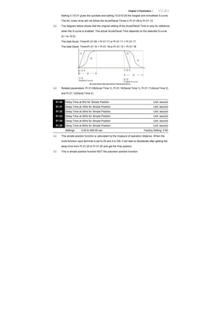
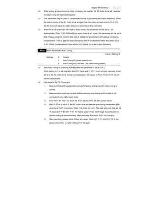
![Appendix C How to Select the Right AC Motor Drive |
Revision Jan 2012, 08EE, SW--PW V1.15/CTL V2.15
C-2
C.1 Capacity Formulas
1. When one AC motor drive operates one motor
The starting capacity should be less than 1.5x rated capacity of AC motor drive
The starting capacity=
)(_____5.1
375cos973
2
kVAdrivemotorACofcapacitythe
t
NGD
T
Nk
A
L ×≤⎟⎟
⎠
⎞
⎜⎜
⎝
⎛
×+
××
×
ϕη
2. When one AC motor drive operates more than one motor
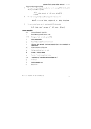
2.1 The starting capacity should be less than the rated capacity of AC motor drive
Acceleration time ≦60 seconds
The starting capacity=
( )[ ] ( ) )(_____5.11
cos
111 kVAdrivemotorACofcapacitythek
n
n
Pknn
Nk
sCss
T
s
T ×≤+=+
×
×
⎥
⎥
⎥
⎦
⎤
⎢
⎢
⎢
⎣
⎡
−−
ϕη
Acceleration time ≧60 seconds
The starting capacity=
( )[ ] ( ) )(_____1
cos
111 kVAdrivemotorACofcapacitythek
n
n
Pknn
Nk
sCss
T
s
T ≤+=+
×
×
⎥
⎥
⎥
⎦
⎤
⎢
⎢
⎢
⎣
⎡
−−
ϕη
2.2 The current should be less than the rated current of AC motor drive(A)
Acceleration time ≦60 seconds
)(______5.111 AdrivemotorACofcurrentratedthekn
nIn SM
T
S
T ×≤++ ⎥
⎦
⎤
⎢
⎣
⎡
⎟
⎠
⎞⎜
⎝
⎛ −
Acceleration time ≧60 seconds
)(______11 AdrivemotorACofcurrentratedthekn
nIn SM
T
S
T ≤++ ⎥
⎦
⎤
⎢
⎣
⎡
⎟
⎠
⎞⎜
⎝
⎛ −](https://image.slidesharecdn.com/vfd-emen20120118-140613014256-phpapp01/85/Vfd-e-m-en_20120118-308-320.jpg)
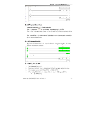
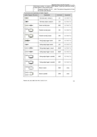
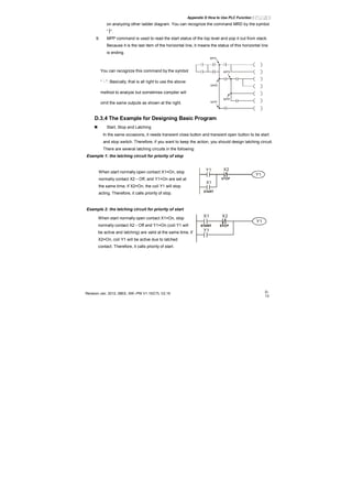
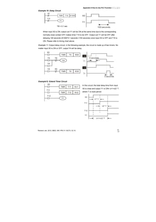
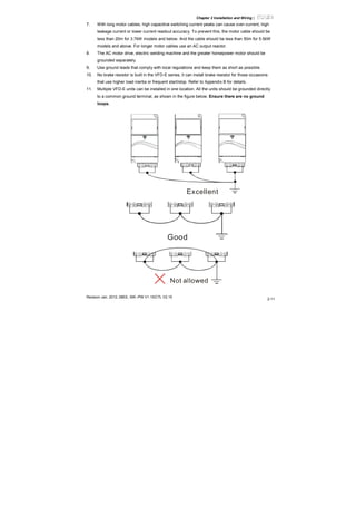
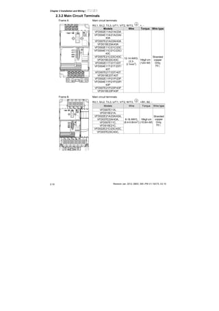
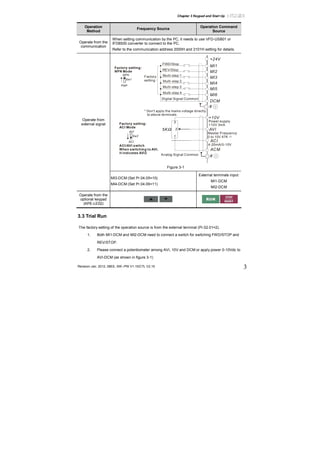
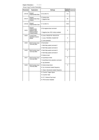
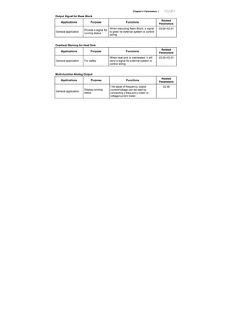
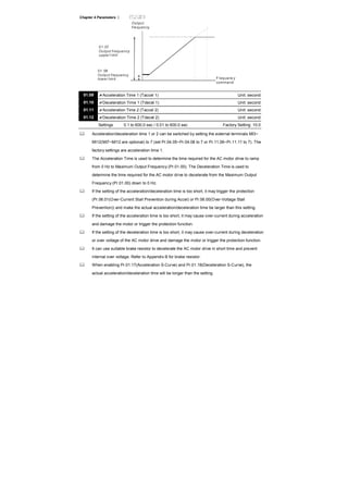
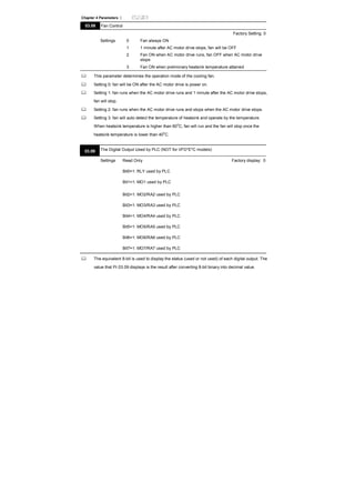
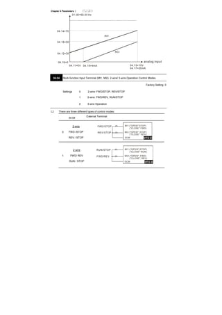
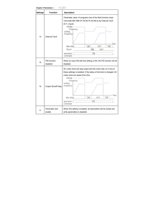
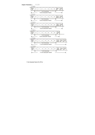
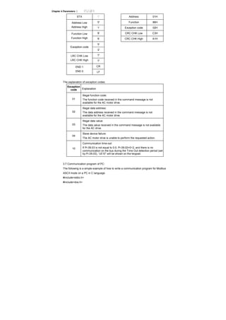
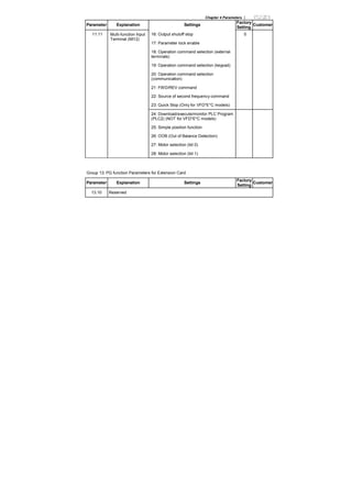
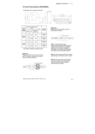
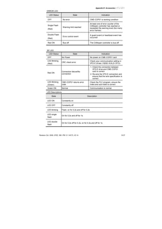
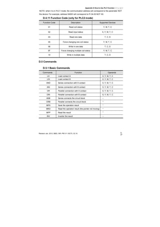
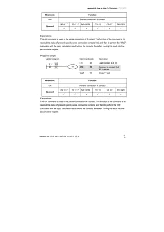
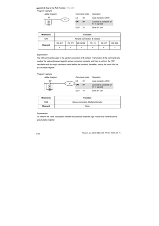
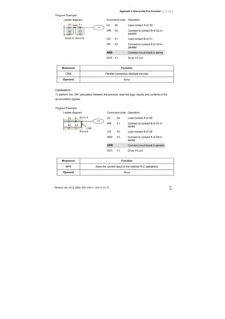
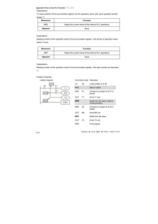
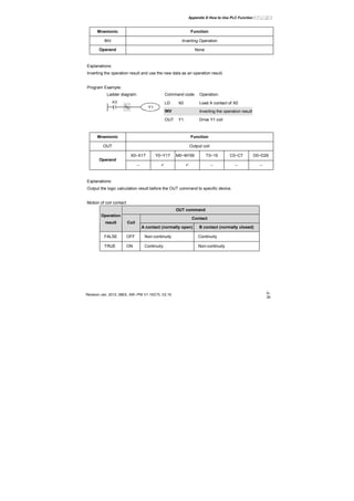
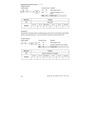
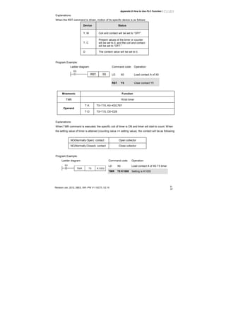
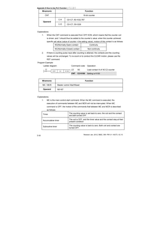
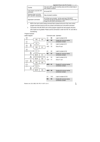
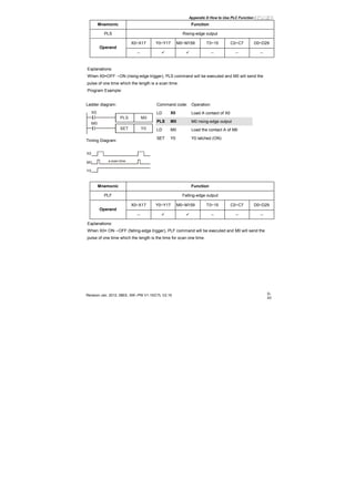
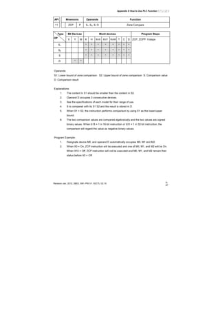
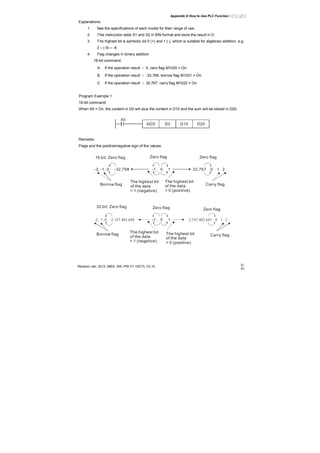
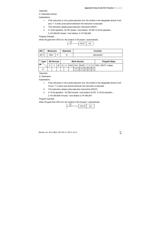
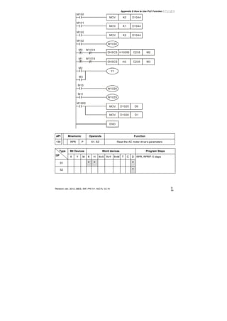
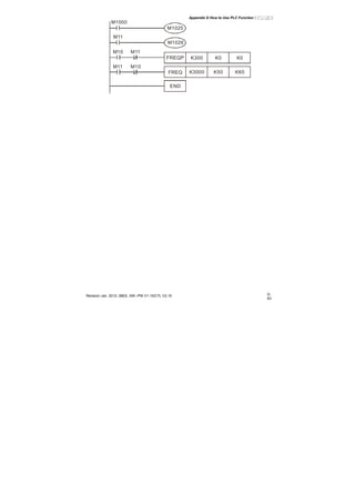
![Appendix D How to Use PLC Function|
Revision Jan. 2012, 08EE, SW--PW V1.15/CTL V2.15
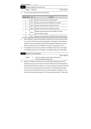
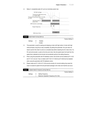
D-20
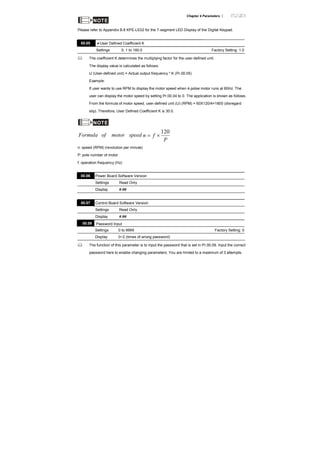
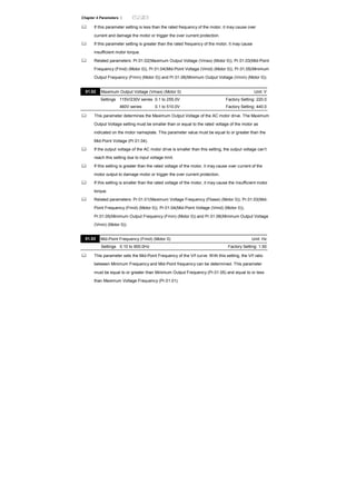
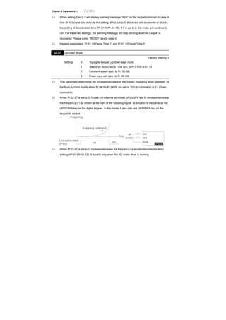
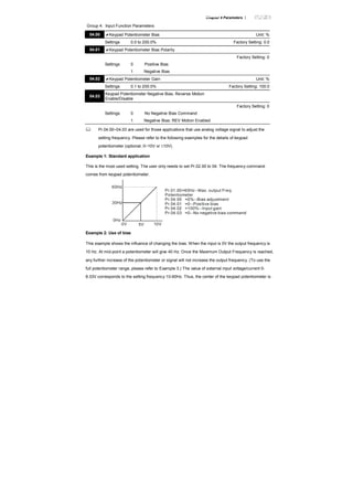
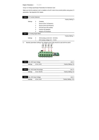
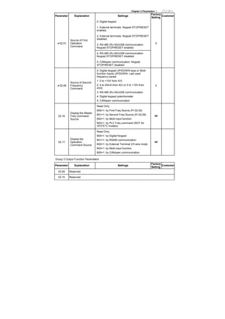
X0
X10
Y0
Y0
1
2
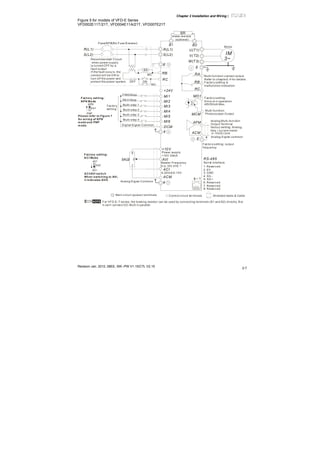
Y0 is repeated
The output of Y0 will be decided by circuit
○2 , i.e. decided by On/Off of X10.
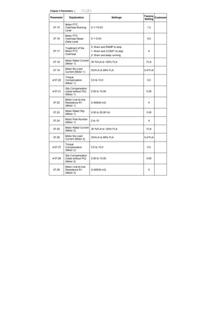
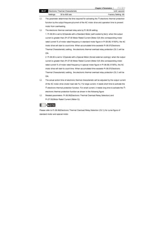
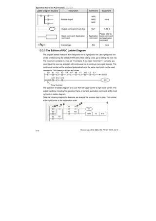
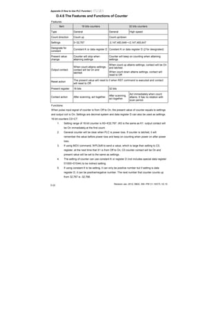
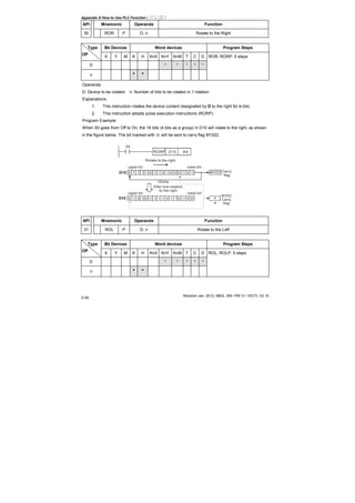
D.4.3 Value, Constant [K] / [H]
K Decimal K-32,768 ~ K32,767 (16-bit operation)
Constant
H Hexadecimal H0000 ~ HFFFF (16-bit operation)
There are five value types for DVP-PLC to use by the different control destination. The
following is the explanation of value types.
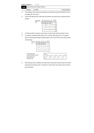
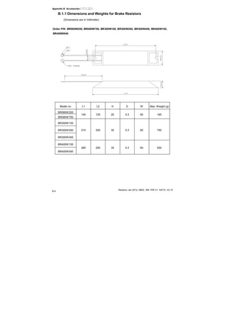
1. Binary Number (BIN)
It uses binary system for the PLC internal operation or storage. The relative information of
binary system is in the following.
Bit : Bit is the basic unit of binary system, the status are 1 or 0.
Nibble : It is made up of continuous 4 bits, such as b3~b0. It can be used to represent
number 0~9 of decimal or 0~F of hexadecimal.
Byte : It is made up of continuous 2 nibbles, i.e. 8 bits, b7~b0. It can used to represent
00~FF of hexadecimal system.
Word : It is made up of continuous 2 bytes, i.e. 16 bits, b15~b0. It can used to represent
0000~FFFF of hexadecimal system.
Double
Word
: It is made up of continuous 2 words, i.e. 32 bits, b31~b0. It can used to
represent 00000000~FFFFFFFF of hexadecimal system.
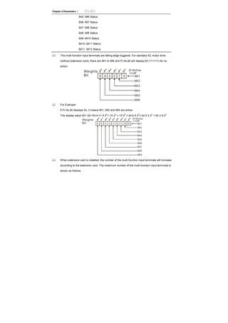
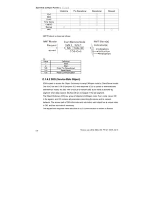
The relations among bit, nibble, byte, word, and double word of binary number are shown as
follows.
NB0NB1NB2NB3NB4NB5NB6NB7
BY3 BY2 BY1 BY0
W1
DW
W0
Double Word
Word
Byte
Nibble
Bit
2. Octal Number (OCT)
The numbers of external input and output terminal of DVP-PLC use octal number.
Example:
External input: X0~X7, X10~X17…(device number)](https://image.slidesharecdn.com/vfd-emen20120118-140613014256-phpapp01/85/Vfd-e-m-en_20120118-333-320.jpg)

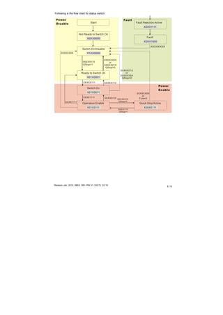

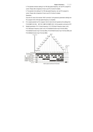
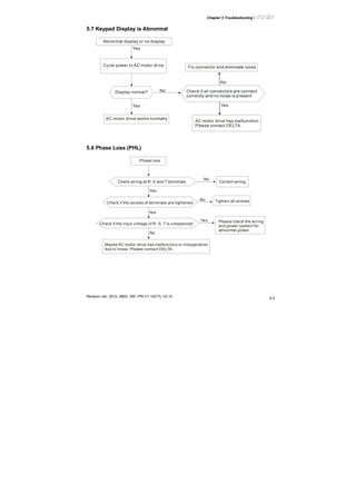
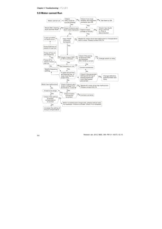
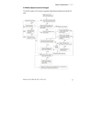
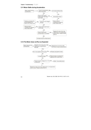
This document provides safety guidelines and instructions for installing and operating an AC motor drive. It explains that the drive should only be installed by qualified personnel who have read the manual. Several dangers are listed, including lethal voltages that can remain after power is turned off. Correct grounding, wiring and motor selection are emphasized. Troubleshooting tips and maintenance guidelines are also included to ensure safe and proper operation of the equipment.


![Ct2000 pro plus_manual_english[1]](https://cdn.slidesharecdn.com/ss_thumbnails/ct2000proplusmanualenglish1-140613213527-phpapp02-thumbnail.jpg?width=640&height=640&fit=bounds)

![Ct2000 es manual_english_version_1[1].0](https://cdn.slidesharecdn.com/ss_thumbnails/ct2000esmanualenglishversion11-140613213448-phpapp01-thumbnail.jpg?width=640&height=640&fit=bounds)


