SlideShare a Scribd company logo
1 of 205
Download to read offline
I
Thank you for purchasing LS Variable Frequency Drives!
SAFETY INSTRUCTIONS
To prevent injury and property damage, follow these
instructions. Incorrect operation due to ignoring instructions
will cause harm or damage. The seriousness of which is
indicated by the following symbols.
DANGER
WARNING
CAUTION
This symbol indicates the possibility of
death or serious injury
This symbol indicates the possibility of
injury or damage to property
This symbol indicates the instant death or
serious injury if you don’t follow instructions
■ The meaning of each symbol in this manual and on your equipment is as
follows.
This is the safety alert symbol.
Read and follow instructions carefully to avoid dangerous situation.
This symbol alerts the user to the presence of “dangerous voltage”
inside the product that might cause harm or electric shock.
■ After reading this manual, keep it in the place that the user always can
contact easily.
■ This manual should be given to the person who actually uses the products
and is responsible for their maintenance.
II
WARNING
n Do not remove the cover while power is applied or the unit is in
operation.
Otherwise, electric shock could occur.
n Do not run the inverter with the front cover removed.
Otherwise, you may get an electric shock due to high voltage terminals or charged
capacitor exposure.
n Do not remove the cover except for periodic inspections or wiring,
even if the input power is not applied.
Otherwise, you may access the charged circuits and get an electric shock.
n Wiring and periodic inspections should be performed at least 10
minutes after disconnecting the input power and after checking the
DC link voltage is discharged with a meter (below DC 30V).
Otherwise, you may get an electric shock.
n Operate the switches with dry hands.
Otherwise, you may get an electric shock.
n Do not use the cable when its insulating tube is damaged.
Otherwise, you may get an electric shock.
n Do not subject the cables to scratches, excessive stress, heavy
loads or pinching.
Otherwise, you may get an electric shock.
III
CAUTION
n Install the inverter on a non-flammable surface. Do not place
flammable material nearby.
Otherwise, fire could occur.
n Disconnect the input power if the inverter gets damaged.
Otherwise, it could result in a secondary accident and fire.
n Do not touch the inverter while the input power is applied or after
removed. It will remain hot for a couple of minutes.
Otherwise, you may get bodily injuries such as skin-burn or damage.
n Do not apply power to a damaged inverter or to an inverter with
parts missing even if the installation is complete.
Otherwise, electric shock could occur.
n Do not allow lint, paper, wood chips, dust, metallic chips or other
foreign matter into the drive.
Otherwise, fire or accident could occur.
OPERATING PRECAUTIONS
(1) Handling and installation
¨ Handle according to the weight of the product.
¨ Do not stack the inverter boxes higher than the number recommended.
¨ Install according to instructions specified in this manual.
¨ Do not open the cover during delivery.
¨ Do not place heavy items on the inverter.
¨ Check the inverter mounting orientation is correct.
¨ Do not drop the inverter, or subject it to impact.
¨ Use the ground impedance of 100ohm or less for 200 V Class and 10ohm or less for
400V class.
¨ Take protective measures against ESD (Electrostatic Discharge) before touching the
pcb for inspection or installation.
¨ Use the inverter under the following environmental conditions:
IV
Ambient
temp.
- 10 ~ 40 ℃ (non-freezing)
Relative
humidity
90% RH or less (non-condensing)
Storage
temp.
- 20 ~ 65 ℃
Location
Protected from corrosive gas, combustible gas, oil mist
or dust
Altitude,
Vibration
Max. 1,000m above sea level, Max. 5.9m/sec2
(0.6G) or
less
Environment
Atmospheric
pressure
70 ~ 106 kPa
(2) Wiring
¨ Do not connect a power factor correction capacitor, surge suppressor, or RFI filter to
the output of the inverter.
¨ The connection orientation of the output cables U, V, W to the motor will affect the
direction of rotation of the motor.
¨ Incorrect terminal wiring could result in the equipment damage.
¨ Reversing the polarity (+/-) of the terminals could damage the inverter.
¨ Only authorized personnel familiar with LS inverter should perform wiring and
inspections.
¨ Always install the inverter before wiring. Otherwise, you may get an electric shock or
have bodily injury.
(3) Trial run
¨ Check all parameters during operation. Changing parameter values might be required
depending on the load.
¨ Always apply permissible range of voltage to the each terminal as indicated in this
manual. Otherwise, it could lead to inverter damage.
(4) Operation precautions
¨ When the Auto restart function is selected, stay away from the equipment as a motor
will restart suddenly after an alarm stop.
¨ The Stop key on the keypad is valid only when the appropriate function setting has
been made. Prepare an emergency stop switch separately.
¨ If an alarm reset is made with the reference signal present, a sudden start will occur.
Check that the reference signal is turned off in advance. Otherwise an accident could
occur.
¨ Do not modify or alter anything inside the inverter.
¨ Motor might not be protected by electronic thermal function of inverter.
¨ Do not use a magnetic contactor on the inverter input for frequent starting/stopping of
the inverter.
¨ Use a noise filter to reduce the effect of electromagnetic interference. Otherwise
nearby electronic equipment may be affected.
V
¨ In case of input voltage unbalance, install AC reactor. Power Factor capacitors and
generators may become overheated and damaged due to potential high frequency
noise transmitted from inverter.
¨ Use an insulation-rectified motor or take measures to suppress the micro surge voltage
when driving 400V class motor with inverter. A micro surge voltage attributable to
wiring constant is generated at motor terminals, and may deteriorate insulation and
damage motor.
¨ Before operating unit and prior to user programming, reset user parameters to default
settings.
¨ Inverter can easily be set to high-speed operations, Verify capability of motor or
machinery prior to operating unit.
¨ Stopping torque is not produced when using the DC-Break function. Install separate
equipment when stopping torque is needed.
(5) Fault prevention precautions
¨ Provide a safety backup such as an emergency brake which will prevent the machine
and equipment from hazardous conditions if the inverter fails.
(6) Maintenance, inspection and parts replacement
¨ Do not conduct a megger (insulation resistance) test on the control circuit of the
inverter.
¨ Refer to Chapter 8 for periodic inspection (parts replacement).
(7) Disposal
¨ Handle the inverter as an industrial waste when disposing of it.
(8) General instructions
Many of the diagrams and drawings in this instruction manual show the inverter without a circuit
breaker, a cover or partially open. Never run the inverter like this. Always place the cover with
circuit breakers and follow this instruction manual when operating the inverter.
VI
(9) UL Marking
1. Short Circuit Rating
“Suitable For Use On A Circuit Capable Of Delivering Not More Than Table1 RMS Symmetrical
Amperes, 240V for 240V rated inverters, 480V for 480V rated inverters Volts Maximum,”
Table 1. RMS Symmetrical Amperes for iS5 series.
Model Rating
SV008iS5-2, SV008iS5-4, SV015iS5-2, SV015iS5-4, SV022iS5-2, SV022iS5-4,
SV037iS5-2, SV037iS5-4,SV055iS5-2, SV055iS5-4, SV075iS5-2, SV075iS5-4,
SV110iS5-2, SV110iS5-4, SV150iS5-2, SV150iS5-4,SV185iS5-2, SV185iS5-4,
SV220iS5-2, SV220iS5-4, SV3005iS5-2, SV300iS5-4, SV370iS5-2, SV370iS5-4
5,000A
SV450iS5-2, SV450iS5-4, SV550iS5-2, SV550iS5-4, SV750iS5-4, 10,000A
2. OVERLOAD PROTECTION
IOLT: IOLT(inverter Overload Trip) protection is activated at 150% of the inverter rated current for
1 minute and greater.
OLT : Inverter shuts off its output when inverter output current exceeds its overload trip level for
overload trip time. OLT is selected when FU1-56 is set to “Yes” and activated at 120% of FU1-57
[Motor rated current] for 60 sec set in FU1-58.
3. OVER SPEED PROTECTION
“Not Provided With Overspeed Protection”.
4.Risk of Electric Shock
More than one disconnect switch may be required to de-energize the equipment before servicing.
1
CONTENTS
SAFETY INSTRUCTIONS I
USER SELECTION GUIDE (IS5 SPECIFICATIONS).......................................................................................... 3
CHAPTER 1 - INSTALLATION........................................................................................................................ 6
1.1 Inspection..............................................................................................................................................................6
1.2 Environmental Conditions..................................................................................................................................6
1.3 Mounting................................................................................................................................................................6
1.4 Other Precautions................................................................................................................................................7
1.5 Dimensions ...........................................................................................................................................................8
1.6 Basic Wiring........................................................................................................................................................13
1.7 Power Terminals.................................................................................................................................................14
1.8 Control Terminals...............................................................................................................................................19
CHAPTER 2 - OPERATION ........................................................................................................................... 23
2.1 Parameter Groups..............................................................................................................................................23
2.2 LCD Keypad ........................................................................................................................................................24
2.3 7-Segment Keypad.............................................................................................................................................28
2.4 Operation Method...............................................................................................................................................32
2.5 Operating Example.............................................................................................................................................33
CHAPTER 3 - VARIOUS FUNCTION SETTING & DESCRIPTION............................................................. 38
3.1 Function Setting.................................................................................................................................................38
3.2 Operation Example.............................................................................................................................................46
CHAPTER 4 - QUICK-START PROCEDURES............................................................................................. 51
4.1 Operating using keypad....................................................................................................................................52
4.2 Operation using Control Terminals.................................................................................................................53
4.3 Operation using Keypad and Control Terminals ..........................................................................................54
CHAPTER 5 - PARAMETER LIST................................................................................................................. 56
5.1 Drive Group [DRV]..............................................................................................................................................56
5.2 Function 1 Group [FU1].....................................................................................................................................58
5.3 Function 2 Group [FU2].....................................................................................................................................60
5.4 Input/Output Group [I/O] ...................................................................................................................................64
5.5 External Group [EXT].........................................................................................................................................70
5.6 Communication Group [COM]..........................................................................................................................74
5.7 Application Group [APP]...................................................................................................................................75
5.8 Sub-Board Selection Guide According To Function....................................................................................77
CHAPTER 6 - PARAMETER DESCRIPTION ............................................................................................... 79
6.1 Drive group [DRV]..............................................................................................................................................79
6.2 Function 1 Group [FU1].....................................................................................................................................87
6.3 Function 2 Group [FU2].....................................................................................................................................99
6.4 Input/Output Group [I/O] .................................................................................................................................118
6.5 External Group [EXT].......................................................................................................................................136
6.6 Application Group [APP].................................................................................................................................145
2
CHAPTER 7 - OPTIONS ...............................................................................................................................153
7.1 Sub-A board.......................................................................................................................................................155
7.2 Sub-B Board......................................................................................................................................................157
7.3 Sub-C Board (Isolated) ....................................................................................................................................161
7.4 Communication option boards.......................................................................................................................163
7.5 Keypad................................................................................................................................................................165
7.6 DB Resistors......................................................................................................................................................167
7.7 DB (Dynamic Brake) Unit.................................................................................................................................175
CHAPTER 8 - TROUBLESHOOTING & MAINTENANCE..........................................................................181
8.1 Fault Display......................................................................................................................................................181
8.2 Fault Remedy.....................................................................................................................................................183
8.3 Troubleshooting................................................................................................................................................185
8.4 How to Check Power Components................................................................................................................186
8.5 Maintenance ......................................................................................................................................................187
8.6 Daily and Periodic Inspection Items..............................................................................................................188
APPENDIX A - FUNCTIONS BASED ON USE................................................................................................189
APPENDIX B - PARAMETERS BASED ON APPLICATION..........................................................................190
APPENDIX C- PERIPHERAL DEVICES...........................................................................................................192
DECLARATION OF CONFORMITY..................................................................................................................194
3
USER SELECTION GUIDE (iS5 SPECIFICATIONS)
230V Class (1 ~ 30HP)
Model Number
(SV xxx iS5 - 2)
008 015 022 037 055 075 110 150 185 220
HP 1 2 3 5 7.5 10 15 20 25 30Motor
Rating1 kW 0.75 1.5 2.2 3.7 5.5 7.5 11 15 18.5 22
Capacity2 [kVA] 1.9 3.0 4.5 6.1 9.1 12.2 17.5 22.9 28.2 33.5
FLA [A] 5 8 12 16 24 32 46 60 74 88
Frequency 0 ~ 400 Hz (Sensorless Vector Control: 0 ~ 300Hz, Sensored Vector Control: 0 ~ 120 Hz)
Output
Ratings
Voltage 200 ~ 230 V 3
Voltage 3 Phase, 200 ~ 230 V (± 10 %)Input
Ratings Frequency 50 ~ 60 Hz (±5 %)
Braking Circuit On Board On Board
Optional
(DB Resistor)
Optional (DB Resistor)
Max. Braking
Torque
100% 100% 100%
Max. Continuous
Baking Time
5 seconds 5 seconds 15 seconds
Dynamic
Braking4
Max. Duty 3 % ED 2 % ED
20%,
Continuous
10 % ED
Weight [kg] 4.7 4.7 4.8 4.9 7.7 7.7 13.9 14.4 20 20
230V Class (40 ~ 75HP)
Model Number
(SV xxx iS5 - 2)
300 370 450 550
HP 40 50 60 75Motor
Rating1 kW 30 37 45 55
Capacity2 [kVA] 46 55 68 84
FLA [A] 122 146 180 220
Frequency 0 ~ 400 Hz (Sensorless Vector Control: 0 ~ 300Hz, Sensored Vector Control: 0 ~ 120 Hz)
Output
Ratings
Voltage 200 ~ 230 V 3
Voltage 3 Phase, 200 ~ 230 V (± 10 %)Input
Ratings Frequency 50 ~ 60 Hz (±5 %)
Braking Circuit Optional (Braking Unit, Resistor)
Max. Braking
Torque
Max. Continuous
Baking Time
Dynamic
Braking4
Max. Duty
20%, Continuous
Weight [kg] 42 42 61 61
1
Indicates the maximum applicable capacity when using a 4-Pole LG motor.
2
Rated capacity (√3*V*I) is based on 220V for 200V class and 440V for 400V class.
3
Maximum output voltage will not be greater than the input voltage. Output voltage less than the input voltage may be programmed.
4
1~5 HP inverters have internal braking resistors as standard. 7.5~100 HP inverters utilize optional braking resistors.
4
460/480 V Class (1 ~ 30HP)
Model Number
(SV xxx iS5 - 4)
008 015 022 037 055 075 110 150 185 220
HP 1 2 3 5 7.5 10 15 20 25 30Motor
Rating1 kW 0.75 1.5 2.2 3.7 5.5 7.5 11 15 18.5 22
Capacity2 [kVA] 1.9 3.0 4.5 6.1 9.1 12.2 18.3 22.9 29.7 34.3
FLA [A] 2.5 4 6 8 12 16 24 30 39 45
Frequency 0 ~ 400 Hz (Sensorless Vector Control: 0 ~ 300Hz, Sensored Vector Control: 0 ~ 120 Hz)
Output
Ratings
Voltage 380 ~ 460 V, 380 ~ 480 V 3
Voltage 3 Phase, 380 ~ 460 V (± 10 %), 380 ~ 480 V (± 10 %) (Special type available from ‘2004)5Input
Ratings Frequency 50 ~ 60 Hz (±5 %)
Braking Circuit
On Board On Board
Optional
(DB Resistor)
Optional (DB Resistor)
Max. Braking
Torque
100% 100% 100%
Max. Continuous
Baking Time
5 seconds 5 seconds 15 seconds
Dynamic
Braking4
Max. Duty 3 % ED 2 % ED
20%
Continuous
10 % ED
Weight [kg] 4.7 4.7 4.8 4.9 7.7 7.7 13.9 14.4 20 20
460/480 V Class (40~100HP)
Model Number
(SV xxx iS5 - 4)
300 370 450 550 750
HP 40 50 60 75 100Motor
Rating1 kW 30 37 45 55 75
Capacity2 [kVA] 45 56 68 82 100
FLA [A] 61 75 91 110 152
Frequency 0 ~ 400 Hz (Sensorless Vector Control: 0 ~ 300Hz, Sensored Vector Control: 0 ~ 120 Hz)
Output
Ratings
Voltage 380 ~ 460 V, 380 ~ 480 V 3
Voltage 3 Phase, 380 ~ 460 V (± 10 %), 380 ~ 480 V(± 10 %) (Special type available from ‘2004) 6Input
Ratings Frequency 50 ~ 60 Hz (±5 %)
Braking Circuit Optional (Braking Unit, Resistor)
Max. Braking
Torque
Max. Continuous
Baking Time
Dynamic
Braking4
Max. Duty
20%, Continuous
Weight [kg] 45 45 63 63 68
5
When applying input voltage of 507~528 V range, derate the load 10%. For example, when applying 507 V to 5.5kW inverters (rated
current 12A), the max. rated output current would be 10.8A, calculated by multiplying 12A by 0.9 (90%).
6
Same as above.
5
Control Method V/F Control, Sensorless Vector Control, Sensored Vector Control (Velocity, Torque) Selectable
Frequency Setting
Resolution
Digital Reference: 0.01 Hz (Below 100 Hz), 0.1 Hz (Over 100 Hz)
Analog Reference: 0.03 Hz / 60 Hz
Frequency Accuracy Digital: 0.01 % of Max. Output Frequency
Analog: 0.1 % of Max. Output Frequency
V/F Ratio Linear, Squared Pattern, User V/F
Overload Capacity 150 % of Rated Current for 1 Min., 200% of Rated Current for 0.5 sec. (Characteristic is
Inversely Proportional to Time)
CONTROL
Torque Boost Manual Torque Boost (0 ~ 15 %), Auto Torque Boost
Operation Method Key / Terminal / Communication Operation
Frequency Setting Analog: 0 ~ 10V / 4 ~ 20mA / Additional port for Sub-Board (0 ~ 10V)
Digital: Keypad
Start Signal Forward, Reverse
Multi-Step Up to 8 Speeds can be Set (Use Multi-Function Terminal)
Multi Step Accel/Decel
Time
0 ~ 6,000 sec, Up to 4 Types can be Set and Selected for Each Setting (Use Multi- Function
Terminal). Accel/Decel Pattern: Linear, U-Curve, S-Curve
Emergency Stop Interrupts the Output of Inverter
Jog Jog Operation
Auto Operation Operates from Internal Sequence by Setting Multi-Function Terminal (5 Way * 8 Step)
InputSignal
Fault Reset Trip Status is Removed when Protection Function is Active
Operating Status Frequency Detection Level, Overload Alarm, Stalling, Over Voltage, Under Voltage, Inverter
Overheating, Running, Stop, Constant Speed, Inverter By-Pass, Speed Searching, Auto-
Operation Step, Auto-Operation Sequence
Fault Output Contact Output (30A, 30C, 30B) – AC250V 1A, DC30V 1A
OutputSignal
Indicator Choose 1 from Output Frequency, Output Current, Output Voltage, DC Voltage, Output Torque
(Output Voltage: 0 ~ 10V)
OPERATION
Operation Function DC Braking, Frequency Limit, Frequency Jump, Second Function, Slip Compensation, Reverse
Rotation Prevention, Auto Restart, Inverter By-Pass, Auto-Tuning, PID Control
Inverter Trip Over Voltage, Under Voltage, Over Current, Fuse Open, Ground Fault, Inverter Overheating,
Motor Overheating, Output Phase Open, Overload Protection, External Fault 1, 2,
Communication Error, Loss of Speed Command, Hardware Fault, Option Fault, Overspeed,
M/C Fail etc.
Inverter Alarm Stall Prevention, Overload Alarm, Temperature Sensor Fault
Protection
Momentary Power Loss Auto Restart function activated when FU2-21 [Restart after fault reset] set to 1 (Yes)
Operation
Information
Output Frequency, Output Current, Output Voltage, Frequency Value Setting, Operating
Speed, DC Voltage, Output Torque
Display
Keypad
Trip Information Indicates a Fault when the Protection Function activates, Retains Up to 5 Faults
Ambient Temperature -10 °C ~ 40 °C (14 °F ~ 104 °F), CE Certification: 41 °F ~ 104 °F (5 °C ~ 40 °C)
Storage Temperature -20 °C ~ 65 °C (-4 °F ~ 149 °F)
Ambient Humidity Less Than 90 % RH Max. (Non-Condensing), CE Certification: 5 ~85% (Non-Condensing)
Altitude - Vibration Below 1,000m or 3,300ft · Below 5.9m/sec2 (=0.6g)
Environment
Application Site No Corrosive Gas, Combustible Gas, Oil Mist, or Dust
Cooling Method Forced Air Cooling
6
CHAPTER 1 - INSTALLATION
1.1 Inspection
l Inspect the inverter for any damage that may have occurred during shipping.
l Check the nameplate on the inverter. Verify the inverter unit is the correct one for the application. The numbering
system for the inverter is as shown below.
LS Inverter Motor Capacity Series Name Input Voltage
008: 1 HP 075: 10 HP 2: 200 ~ 230V (±10%) (50/60Hz)
015: 2 HP 110: 15 HP 4: 380 ~ 460V (±10%) (50/60Hz) UL Listed
022: 3 HP 150: 20 HP 4: 380 ~ 480V(±10%) (50/60Hz)
037: 5 HP 185: 25 HP
055: 7.5 HP 220: 30 HP N: Without Keypad
O/E: UL Open/Enclosed Type 1
DB: Built-in DB Unit
1.2 Environmental Conditions
l Verify ambient condition for the mounting location.
- Ambient temperature should not be below 14ºF (-10ºC) or exceed 104ºF (40ºC).
- Relative humidity should be less than 90% (non-condensing).
- Altitude should be below 3,300ft (1,000m).
l Do not mount the inverter in direct sunlight and isolate it from excessive vibration.
l If the inverter is going to be installed in an environment with high probability of penetration of dust, it must be
located inside watertight electrical boxes, in order to get the suitable IP degree.
1.3 Mounting
l The inverter must be mounted vertically with sufficient horizontal and vertical space between adjacent equipment
(A= Over 100mm, B= Over 50mm). However, A= Over 500mm and B= 200mm should be obtained for
inverters with 40Hp and above.
B
A
B
A
008SV iS5 2 XXX U
…
(480)
Chapter 1 – Installation
7
1.4 Other Precautions
l Do not carry the inverter by the front cover.
l Do not install the inverter in a location where excessive vibration is present. Be cautious when installing on
presses or moving equipment.
l The life span of the inverter is greatly affected by the ambient temperature. Install in a location where temperature
are within permissible limits (- 10 ~ 40 ℃).
l The inverter operates at high-temperatures - install on a non-combustible surface.
l Do not install the inverter in high-temperature or high-humidity locations.
l Do not install the inverter in a location where oil mist, combustible gas, or dust is present. Install the inverter in a
clean location or in an enclosed panel, free of foreign substance.
l When installing the inverter inside a panel with multiple inverters or a ventilation fan, use caution.
If installed incorrectly, the ambient temperature may exceed specified limits.
l Install the inverter using screws or bolts to insure the inverter is firmly fastened.
Inverter
GOOD (O) BAD (X)
Inverter
Cooling fan
Panel Panel
Inverter
Inverter
[When installing several inverters in a panel]
Ventilating fan
GOOD (O) BAD (X)
[When installing a ventilating fan in a panel]
UL Remark (File number: E124949):
“Only intended for use in an enclosure with maximum surrounding air temperature of 45℃” or
equivalent: Models SV022iS5-2/4, SV037iS5-2/4, SV055iS5-4 (not -2), SV075iS5-4 (not -2),
SV110iS5-2/4, SV150iS5-2/4, SV185iS5-2/4 and SV220iS5-2/4.
Chapter 1 – Installation
8
1.5 Dimensions
n Frame # 1: 1 ~ 5 HP
n Frame # 2: 7.5 ~ 10 HP
mm (inches)
Frame HP Model Number W1 W2 H1 H2 D1
1 SV008iS5-2/4
2 SV015iS5-2/4
3 SV022iS5-2/4
Frame # 1
5 SV037iS5-2/4
150
(5.91)
130
(5.12)
284
(11.18)
269
(10.69)
156.5
(6.16)
7.5 SV055iS5-2/4
Frame # 2
10 SV075iS5-2/4
200
(7.87)
180
(7.09)
355
(13.98)
340
(13.39)
182.5
(7.19)
Chapter 1 – Installation
9
n Frame # 3: 15 ~ 20 HP
n Frame # 4: 25 ~ 30 HP
mm (inches)
Frame HP Model Number W1 W2 H1 H2 D1
15 SV110iS5-2/4
Frame # 3
20 SV150iS5-2/4
250
(9.84)
230
(9.06)
385
(15.16)
370
(14.57)
201
(7.91)
25 SV185iS5-2/4
Frame # 4
30 SV220iS5-2/4
304
(11.97)
284
(11.18)
460
(18.11)
445
(17.52)
234
(9.21)
Chapter 1 – Installation
10
n Frame # 5: 40~50HP
STARVERT-iS5
mm (inches)
Frame HP Model Number W1 W2 H1 H2 D1
40 SV300iS5-2/4
Frame # 5
50 SV370iS5-2/4
350
(13.78)
270
(10.63)
680
(28.77)
662
(26.06)
311
(12.25)
Chapter 1 – Installation
11
n Frame # 6: 60~75HP(200V)
STARVERT-iS5
mm (inches)
Frame HP Model Number W1 W2 H1 H2 D1
60 SV450iS5-2
Frame # 6
75 SV550iS5-2
397
(15.63)
275
(10.83)
780
(30.71)
760.5
(29.94)
330
(12.99)
Chapter 1 – Installation
12
n Frame # 7: 60~100HP (400V)
mm (inches)
Frame HP Model Number W1 W2 H1 H2 D1
60 SV450iS5-4
75 SV550iS5-4Frame # 7
100 SV750iS5-4
375
(14.76)
275
(10.83)
780
(30.71)
760.5
(29.94)
330
(12.99)
STARVERT-iS5
Chapter 1 – Installation
13
1.6 Basic Wiring
230/460V
50/60Hz
U
V
W
G ( )
R
S
T
N1
DB Unit(Optional)
5
DB Resistor
φ3
MCCB MC
(Option)
FX
RX
BX
RST
P1
P3
CM
VR
V1
I
5G
(CM)6
+
FM
5G
(CM)
6
(N.O.) 30 A
AXA
AXC
Output Frequency Meter
(0~10V Linear)
2
P2
MOTOR
Potentiometer
(1 kohm, 1/2W)
Speed signal Input3
Forward Run/Stop
Reverse Run/Stop
Inverter Disable
Fault Reset
Multi-functionInput 1
Multi-functionInput 2
Multi-functionInput 3
Common Terminal
FactorySetting:
‘Speed-L’
‘Speed-M’
‘Speed-H’
Power supply for
speed signal:
+ 12V, 10mA
Speed signalinput:
0 ~ 10V
Speed signalinput:
4 ~20mA (250ohm)
Common for
VR, V1, I
Fault output relay
less than AC250V, 1A
less than DC30V, 1A
Multi-functionoutput relay1
less than AC250V, 1A
less than DC30V, 1A
Factory setting: ‘Run’
Note) Main Circuit Terminals ControlCircuit Terminals.
1. The terminal configurationvaries depend on the model number. Please refer to the ‘1.7 Power terminals’.
2. Analog output voltage is adjustable up to 12V.
3. Analog speed command may be set by Voltage, Current orboth.
4. The Common Busbar between P1/L1and P2/L2 must be removed beforeinstalling DC Reactor.
5. 1 ~ 10 HP inverters havebuilt-in braking circuit. Braking resistorsareonlyincludedfor 1 ~ 5HP inverters.
15~30HP invertershave built-inDB unit. 15 ~ 100HP invertersneed optional braking unit and resistor.
6. In case of 40 HP or morethan,the terminal is CM terminalwhich has same electricpotentialwith Common Terminal.
P2/
L21
P1/
L11
DC Bus Choke (Optional)
4
FM
Dynamic
Braking Unit
(Optional)
P N B1 B2
DC Bus Choke DB Resistor
JOG
Jog
Shield
(N.C.) 30 B
30 C
Main Power
Circuit
Control Circuit
Chapter 1 – Installation
14
1.7 Power Terminals
n Type A Configuration: 1 ~ 5 HP (230/460/480V)
R S T G N B1 B2 U V W
n Type B Configuration: 7.5 ~ 10 HP (230/460/480V)
R S T G P N B1 B2 U V W
n Type C Configuration: 15 ~ 30 HP (230/460/480V)
R S T G P1 P2 N U V W
n Type C Configuration: 15 ~ 30 HP (230/460/480V), Built-in DBU model
R S T G P1 B1 B2 U V W
n Type D Configuration: 40~ 75 HP (230V), 40 ~ 100 HP (460/480V)
R S T G U V W P1 P2 N
* Jumper should be removed to connect a DC reactor
Symbols Functions
R
S
T
AC Line Voltage Input
(3 Phase, 200 ~ 230VAC or 380 ~ 460/480 VAC)
G Earth Ground
P
Positive DC Bus Terminal
DB Unit (P-P7) Connection Terminals
(DB Unit may be added when more braking duty (More than 30%ED) is required)
P1
P2
External DC Reactor (P1-P2) and DB Unit (P2-N) Connection Terminals
N
Negative DC Bus Terminal
DB Unit (N-N8) Connection Terminal
B1
B2
Dynamic Braking Resistor (B1-B2) Terminals for 1-30HP inverters
U
V
W
3 Phase Power Output Terminals to Motor
(3 Phase, 200 ~ 230VAC or 380 ~ 460/480 VAC)
“Suitable for use on a circuit capable of delivering not more than 10,000 rms symmetrical amperes,
240 volts maximum for 230V class models and 480 volts maximum for 460V class models.”
7
This P terminal is provided on optional Dynamic Braking Unit.
8
This N terminal is provided on optional Dynamic Braking Unit.
DB Resistor integrated
Chapter 1 – Installation
15
1.7.1 Type A Configuration
As standard on the iS5 inverter, this type of configuration has internal dynamic braking resistor of 3% ED. When an
application requires more braking duty, an external dynamic braking resistor may be connected instead of the internal
resistor.
R S T G N B1 B2 U V W
Figure 1 – Type A Dynamic Braking Resistor Installation
1.7.2 Type B Configuration
A Dynamic Braking Resistor or a Dynamic Braking Unit may be added to iS5 series inverters that have a Type B
configuration power terminal strip.
R S T G P N B1 B2 U V W
Figure 2 – Type B Dynamic Braking Resistor Installation
R S T G P N B1 B2 U V W
Figure 3 – Type B Additional Dynamic Braking Unit and Resistor Installation
Motor
Dynamic Braking Resistor
3 Phase
Power Input
Motor3 Phase
Power Input
Dynamic Braking Resistor
Motor3 Phase
Power Input
Dynamic Braking Resistor
Dynamic
Braking Unit
Chapter 1 – Installation
16
1.7.3 Type C Configuration
A Dynamic Braking Unit or a DC Bus Choke or both of them may be added to iS5 series inverters that have a Type A
Configuration power terminal strip.
Jumper Between P1 and P2 Must Be Removed in Order
to Install a DC Bus Choke.
R S T G P1 P2 N U V W
Figure 4 – Type C Dynamic Braking Unit, DC Bus Choke Installation
R S T G P1 B1 B2 U V W
Figure 5 – Type C Dynamic Braking Resistor
1.7.4 Type D Configuration
R S T G U V W P1 P2 N
Figure 6 – Type D Dynamic Braking Unit, DC Bus Choke Installation
Motor3 Phase
Power Input
Dynamic
Braking
Unit
DC Bus Choke (remove to
wire DC Reactor
Dynamic Braking Resistor
Motor3 Phase
Power Input
Dynamic Braking Resistor
Motor3 Phase
Power Input
Dynamic
Braking
Unit
DB Resistor
DC Bus Choke
(remove to wire DC Reactor)
Chapter 1 – Installation
17
1.7.5 Wiring Power Terminals
n Wiring Precautions
l The internal circuits of the inverter will be damaged if the incoming power is connected and applied to output
terminals (U, V, W).
l Use ring terminals with insulated caps when wiring the input power and motor wiring.
l Do not leave wire fragments inside the inverter. Wire fragments can cause faults, breakdowns, and malfunctions.
l For input and output, use wires with sufficient size to ensure voltage drop of less than 2%.
l Motor torque may drop of operating at low frequencies and a long wire run between inverter and motor.
l When more than one motor is connected to one inverter, total wire length should be less than 200m (656ft). Do
not use a 3-wire cable for long distances. Due to increased leakage capacitance between wires, over-current
protective feature may operate or equipment connected to the output side may malfunction. (But for products of
less than 3.7kW, the wire length should be less than 50m(146ft).) In case of long wire length, it should be required
to lower carrier frequency or use Micro Surge Filter.
Length between Inverter and Motor Up to 50m Up to 100m More than 100m
Allowable Carrier Frequency Less than 15kHz Less than 5kHz Less than 2.5kHz
l Connect only recommended braking resistor between the B1 and B2 terminals. Never short B1 and B2
terminals. Shorting terminals may cause internal damage to inverter.
l The main circuit of the inverter contains high frequency noise, and can hinder communication equipment near the
inverter. To reduce noise, install line noise filters on the input side of the inverter.
l Do not use power factor capacitor, surge killers, or RFI filters on the output side of the inverter. Doing so may
damage these components.
l Always check whether the LCD and the charge lamp for the power terminal are OFF before wiring terminals. The
charge capacitor may hold high-voltage even after the power is disconnected. Use caution to prevent the
possibility of personal injury.
n Grounding
l The inverter is a high switching device, and leakage current may flow. Ground the inverter to avoid electrical shock.
Use caution to prevent the possibility of personal injury.
l Connect only to the dedicated ground terminal of the inverter. Do not use the case or the chassis screw for
grounding.
l The protective earth conductor must be the first one in being connected and the last one in being disconnected.
l As a minimum, grounding wire should meet the specifications listed below. Grounding wire should be as short as
possible and should be connected to the ground point as near as possible to the inverter.
Grounding wire Sizes, AWG (mm²)
Inverter Capacity
200V Class 400VClass
Below 3.7kW (5HP) 12 (3.5) 14 (2)
5.5~7.5kW (7.5~10HP) 10 (5.5) 12 (3.5)
11~15kW (15~20HP) 6 (14) 8 (8)
18.5~22kW (25~30HP) 4 (22) 6 (14)
30~37kW (40~50HP) 4 (22) 6 (14)
45~75kW (60~100HP) 2 (38) 4 (22)
WARNING
Normal stray capacitance between the inverter chassis and the power devices inside the
inverter and AC line can provide a high impedance shock hazard. Do not apply power to the
inverter if the inverter frame (Power terminal G) is not grounded.
Chapter 1 – Installation
18
n Wires and Terminal Lugs
Refer to the following table for wires, terminal lugs, and screws used to connect the inverter power input (R, S, T) and
output (U, V, W). Input and motor output terminal blocks are intended only for use with ring type connectors.
Wire10
Ring Terminals
mm² AWGInverter Capacity
Terminal
Screw
Size
Screw Torque9
(Kgf·cm)/
lb-in
R,S,T U,V,W R,S,T U,V,W R,S,T U,V,W
0.75~2.2kW(1~3HP) M3.5 7.1~12.2 / 6.2~10.6 2-4 2-4 2 2 14 14
3.7 kW (5HP) M3.5 7.1~12.2 / 6.2~10.6 2-4 2-4 3.5 3.5 12 12
5.5 kW (7.5HP) M4 7.1~12.2 / 6.2~10.6 5.5-5 5.5-5 5.5 5.5 10 10
7.5 kW (10HP) M4 7.1~12.2 / 6.2~10.6 14-5 8-5 14 8 6 8
11 kW (15HP) M5 24.5~31.8 / 21.2~27.6 14-5 14-5 14 14 6 6
15 kW (20HP) M5 24.5~31.8 / 21.2~27.6 22-6 22-6 22 22 4 4
18.5 kW (25HP) M6 30.6~38.2 / 26.6~33.2 38-8 38-8 30 30 2 2
22 kW (30HP) M6 30.6~38.2 / 26.6~33.2 38-8 38-8 38 30 2 2
30~37 kW (40~50HP) M8 61.2~91.8 / 53.1~79.7 60-8 60-8 60 60 2/0 2/0
200V
Class
45~55 kW (60~75HP) M10 89.7~122.0 / 77.9~105.9 100-10 100-10 100 100 4/0 4/0
0.75~3.7 kW (1~5HP) M3.5 7.1~12.2 / 6.2~10.6 2-4 2-4 2 2 14 14
5.5 kW (7.5HP) M4 7.1~12.2 / 6.2~10.6 5.5-5 5.5-5 3.5 2 12 14
7.5 kW (10HP) M4 7.1~12.2 / 6.2~10.6 14-5 8-5 3.5 3.5 12 12
11 kW (15HP) M5 24.5~31.8 / 21.2~27.6 14-5 14-5 5.5 5.5 10 10
15 kW (20HP) M5 24.5~31.8 / 21.2~27.6 22-6 22-6 14 8 6 8
18.5 kW (25HP) M6 30.6~38.2 / 26.6~33.2 38-8 38-8 14 8 6 8
22 kW (30HP) M6 30.6~38.2 / 26.6~33.2 38-8 38-8 22 14 4 6
30~37 kW (40~50HP) M8 61.2~91.8 / 53.1~79.7 38-8 38-8 22 22 4 4
45~55 kW (60~75HP) M8 61.2~91.8 / 53.1~79.7 38-8 38-8 38 38 2 2
400V
Class
75 kW (100HP) M8 61.2~91.8 / 53.1~79.7 60-8 60-8 60 60 2/0 2/0
n Power and Motor Connection
R S T G N B1 B2 U V W
9
Apply the rated torque to terminal screws. Loose screws can cause of short circuit or malfunction. Tightening the screws too much
can damage the terminals and cause a short circuit or malfunction.
10
Use copper wires only with 600V, 75℃ ratings.
Motor3 Phase
Power Input
Power supply must be connected
to the R, S, and T terminals.
Connecting it to the U, V, and W
terminals causes internal damages
to the inverter. Arranging the phase
sequence is not necessary.
Motor should be connected to the
U, V, and W terminals.
If the forward command (FX) is on,
the motor should rotate counter
clockwise when viewed from the load
side of the motor. If the motor rotates
in the reverse, switch the U and V
terminals.
Chapter 1 – Installation
19
1.8 Control Terminals
P1 P2 P3 FX RX NC VR V1
30A 30C 30B AXA AXC JOG CM CM BX RST I FM 5G
Type Symbol Name Description
P1, P2, P3
Multi-Function Input
1, 2, 3
Used for Multi-Function Input Terminal.
(Factory default is set to “Multi-Step Frequency 1, 2, 3”.)
FX Forward Run Command Forward Run When Closed and Stopped When Open.
RX Reverse Run Command Reverse Run When Closed and Stopped When Open.
JOG
Jog Frequency
Reference
Runs at Jog Frequency when the Jog Signal is ON. The Direction is set by
the FX (or RX) Signal.
BX Emergency Stop
When the BX Signal is ON the Output of the Inverter is Turned Off. When
Motor uses an Electrical Brake to Stop, BX is used to Turn Off the Output
Signal. When BX Signal is OFF (Not Turned Off by Latching) and FX Signal
(or RX Signal) is ON, Motor continues to Run.
RST Fault Reset Used for Fault Reset.
StartingContactFunctionSelect
CM Sequence Common Common Terminal for Contact Inputs.
NC - Not Used.
VR
Frequency Setting Power
(+12V)
Used as Power for Analog Frequency Setting. Maximum Output is +12V,
100mA.
V1
Frequency Reference
(Voltage)
Used for 0-10V Input Frequency Reference. Input Resistance is 20 KΩ.
I
Frequency Reference
(Current)
Used for 4-20mA Input Frequency Reference. Input Resistance is 250 Ω.
Inputsignal
Analogfrequencysetting
5G11
Frequency Setting
Common Terminal
Common Terminal for Analog Frequency Reference Signal and FM (For
Monitoring).
Analog
FM
Analog Output (0~12V)
(For External Monitoring)
Outputs One of the Following: Output Frequency, Output Current, Output
Voltage, DC Link Voltage, and Torque. Default is set to Output Frequency.
Maximum Output Voltage and Output Current are 0-12V and 1mA, 500Hz.
30A
30C
30B
Fault Contact Output
Activates when Protective Function is Operating. AC250V, 1A or less;
DC30V, 1A or less.
Fault: 30A-30C Closed (30B-30C Open)
Normal: 30B-30C Closed (30A-30C Open)
Outputsignal
Contact
AXA, AXC
Multi-Function Output
Relay
Use After Defining Multi-Function Output Terminal. AC250V, 1A or less;
DC30V, 1A or less.
* Tightening torque of control terminal blocks
TER 1 – 140 Kgf·cm/(93.5 in-lb) TER 2 – 8 Kgf·cm/(5.3 in-lb)
11 In case of above 30kW, it is CM and it has a same electric potential with sequence common terminal CM.
Chapter 1 – Installation
20
1.8.1 Wiring Control Terminals
n Wiring Precautions
l CM and 5G terminals are insulated to each other. Do not connect these terminals with each other and do not
connect these terminals to the power ground. Terminal 5G is indicated as CM from 30kW inverters and has the
same potential as CM (Sequence Common Terminal).
l Use shielded wires or twisted wires for control circuit wiring, and separate these wires from the main power circuits
and other high voltage circuits.
l It is recommended to use the cables of 1.25 mm²(22 AWG) for connection to the control circuit terminals.
n Control Circuit Terminal
l The control input terminal of the control circuit is ON when the circuit is configured to the current flows out of the
terminal, as shown in the following illustration. CM terminal is the common terminal for the contact input signals.
CAUTION
Do not apply voltage to any control input terminals (FX, RX, P1, P2, P3, JOG, BX, RST, CM).
24 VDC
FX
RX
CM
Current
Inverter Circuitry
Resistor
Resistor
External Sequence
Chapter 1 – Installation
21
1.8.2 Keypad Connection
Connect keypad to the keypad connector as illustrated below. The LCD output will not be displayed on the keypad if
the keypad is not connected properly.
Control Board
Control Terminal BlockRelay Output
Terminal Block
Keypad Connector
(CN3)
Sub-Board Connector
Power Supply Input,
Gate Drive Signal Output
Connector Socket
Option Board Connector
Sub-Board
Option Board
Chapter 1 – Installation
22
Notes:
23
CHAPTER 2 - OPERATION
The iS5 series inverter has seven parameter groups separated according to their applications as indicated in the
following table.
The iS5 series inverter provides two kinds of keypad. One is of 32-character alphanumeric LCD keypad and the other
is of 7-Segment LED keypad.
2.1 Parameter Groups
Parameter
Group
LCD Keypad
(Upper left Corner)
7-segment Keypad
(LED is lit)
Description
Drive Group DRV ‘DRV’ LED
Command Frequency, Accel/Decel Time etc.
Basic Parameters
Function 1 Group FU1 ‘FU1’ LED
Max. Frequency, Amount of Torque Boost etc.
Basic Related Parameters
Function 2 Group FU2 ‘FU2’ LED
Frequency Jumps, Max./Min. Frequency Limit etc.
Basic Application Related Parameters
Input / Output
Group
I/O ‘I/O’ LED
Multi-Function Terminal Setting, Auto Operation etc.
Parameters needed for Sequence Operation
Sub-Board Group EXT ‘EXT’ LED Displayed when Sub-Board is Installed.
Option Group COM ‘I/O’ + ‘EXT’ LED Displayed when Option Board is Installed.
Application Group APP
‘FU2’ + ‘I/O’ + ‘EXT’
LED
Traverse, MMC (Multi-Motor Control), Draw etc.
Application Related Parameters
Refer to the function descriptions in chapter 6 for detailed description of each group.
Chapter 2 - Operation
24
2.2 LCD Keypad
LCD keypad can display up to 32 alphanumeric characters, and various settings can be checked directly from the
display. The following is an illustration of the keypad.
32 character, back light,
LCD display. The back
light is adjustable.
The Mode Button moves
you through the seven
program groups: DRV,
FUN1, FUN2, I/O, (EXT),
COM, and APP
The Up and Down
Arrows are used to
move through and
change data.
Reverse Run Button.
The Reverse Run LED
blinks when the drive
Accels or Decels.
The Program Button is
used to go into
programming mode to
change data.
The Enter Button is
used to enter changed
data within a parameter.
[SHIFT] This button is
used to move cursor
across display in
programming mode.
[ESC] This button is used
to move the program
code to DRV 00 form any
program code.
Forward Run Button
The Forward Run LED
blinks when the drive
Accels or Decels.
Stop Button is used to
stop the drive from
running.
The Reset Button is
used to reset Faults.
The LED blinks when
there is a fault.
Chapter 2 - Operation
25
2.2.1 LCD Keypad Display
DRV▶T/K 0.0 A
00 STP 0.00 Hz
Displays Description
1) Parameter Group Displays the parameter group. There are DRV, FU1, FU2, I/O, EXT, COM, APP groups.
2) Run/Stop Source Displays the source of motor Run and Stop
K: Run/Stop using FWD, REV buttons on keypad
T: Run/Stop using control terminal input FX, RX
O: Run/Stop via option board
3) Frequency Setting
Source
Displays the source of command frequency setting
K: Frequency setting using keypad
V: Frequency setting using V1 (0 ~10V) or V1 + I terminal
I: Frequency setting using I (4 ~ 20mA) terminal
U: Up terminal input when Up/Down operation is selected
D: Down terminal input when Up/Down operation is selected
S: Stop status when Up/Down operation is selected
O: Frequency setting via Option board
X: Frequency setting via Sub board
J: Jog terminal input
1 ~ 8: Step frequency operation
* During Auto operation, 2) and 3) display the ‘sequence number/step’.
4) Output Current Displays the Output Current during operation.
5) Parameter Code Displays the code of a group. Use the ▲(Up), ▼(Down) key to move through 0~99 codes.
6) Operating Status Displays the operation information.
STP: Stop Status
FWD: During Forward operation
REV: During Reverse operation
DCB: During DC Braking
LOP: Loss of Reference from Option Board (DPRAM fault)
LOR: Loss of Reference from Option Board (Communication network fault)
LOV: Loss of Analog Frequency Reference (V1: 0~10V)
LOI: Loss of Analog Frequency Reference (I: 4~20mA)
LOS: Loss of Reference from Sub-Board
7) Drive Output Frequency
Command Frequency
Displays the Output Frequency during run.
Displays the Command Frequency during stop.
2) Run/Stop Source 3) Frequency Setting Source
4) Output Current
7) Drive Output Frequency During Run,
Command Frequency During Stop6) Operating Status
5) Parameter Code
1) Parameter group
Chapter 2 - Operation
26
2.2.2 Procedure for Setting Data (LCD Keypad)
1. Press [MODE] key until the desired parameter group is displayed.
2. Press [▲] or [▼] keys to move to the desired parameter code. If you know the desired parameter code, you can
set the code number of each parameter group in “Jump code”, except DRV group.
3. Press [PROG] key to go into the programming mode, the cursor starts blinking.
4. Press [SHIFT/ESC] key to move the cursor to the desired digit.
5. Press [▲] or [▼] keys to change the data.
6. Press [ENT] key to enter the data. The cursor stops blinking.
n Note: Data cannot be changed when:
1) The parameter is not adjustable during the inverter is running. (Refer to the function table in Chapter 5) or
2) Parameter Lock function is activated in FU2-94 [Parameter Lock].
Chapter 2 - Operation
27
2.2.3 Parameter Navigation (LCD Keypad)
The parameter group moves directly to DRV group by pressing [SHIFT/ESC] key in any parameter code.
DRV▶T/K 0.0 A
00 STP 0.00 Hz
FU1▶ Jump code
00 1
FU2▶ Jump code
00 30
MODE
◀
FU1▶Run prohibit
03 None
FU2▶ Last trip-1
01 -------
I/O▶ V1 filter
01 10 ms
DRV▶ Dec. time
02 20.0 sec
FU1▶Acc. pattern
05 Linear
FU2▶ Last trip-2
02 -------
I/O▶ V1 volt x1
02 0.00 V
FU1▶Dec. pattern
06 Linear
FU2▶ Last trip-3
03 -------
I/O▶ V1 freq y1
03 0.00 Hz
DRV▶ Freq mode
04 KeyPad-1
FU1▶ Stop mode
07 Decel
FU2▶ Last trip-4
04 -------
I/O▶ V1 volt x2
04 10.00 V
DRV▶ Step freq-1
05 10.00 Hz
FU1▶ DcSt value
08 50 %
FU2▶ Last trip-5
05 -------
I/O▶ V1 freq y2
05 60.00 Hz
FU1▶ Stall Level
60 150 %
FU2▶ Para. lock
94 0
I/O▶ Way1 / 2D
60 Forward
MODE MODEMODE
MODE
I/O▶ Jump code
00 1
▶
MODE
◀
▶
MODE
◀
▶
MODE
◀
▶
MODE
◀
▶
◀
▶
◀
▶
◀
▶
◀
▶
◀
▶
◀
▶
◀
▶
◀
▶
◀
▶
◀
▶
◀
▶
◀
▶
◀
▶
◀
▶
◀
▶
◀
▶
◀
▶
◀
▶
DRV▶ Drive mode
03 Fx/Rx-1
DRV▶ Fault
12 -------
DRV▶ Acc. time
01 10.0 sec
MODE MODE MODE
MODEMODEMODEMODE
MODE MODE MODE MODE
MODEMODEMODEMODE
MODE MODE MODE MODE
◀
▶
Drive Group FU1 Group FU2 Group I/O Group
.
.
.
.
.
.
.
.
.
.
.
.
Chapter 2 - Operation
28
2.3 7-Segment Keypad
* Parameter Group Display LEDs – When parameter code is located on DRV 20, DRV 21, DRV 22 and DRV 23, respectively by
rotating the encoder knob, the parameter group display LEDs of DRV, FUN1, FUN2, I/O, EXT blink.
LED Parameter Group Description
DRV Drive Group Lit in Drive group.
FU1 FUNCTION 1 Group
Blinks when the parameter code is located on DRV 20 [FUN1].
Lit when FUNCTION 1 group is selected.
FU2 FUNCTION 2 Group
Blinks when the parameter code is located on DRV 21 [FUN2].
Lit when FUNCTION 2 group is selected.
I/O Input/Output Group
Blinks when the parameter code is located on DRV 22 [I/O].
Lit when Input/Output group is selected.
EXT Sub-Board Group
Blinks when the parameter code is located on DRV 23 [EXT].
Lit when Sub-Board group is selected.
This group appears only when a Sub-Board is installed.
I/O + EXT Option Group
Blinks when the parameter code is located on DRV 24 [EXT].
Lit when Option group is selected.
This group appears only when an Option Board is installed.
FU2 + I/O + EXT Application Group Blinks when the parameter code is located on DRV 25 [FUN2].
7-segment display
Encoder knob
Used to move you
through parameter
groups and parameter
code. Also, used to
change data by rotating
knob.
Program Button is used
to go into programming
mode to change data.
Enter Button is used to
enter the changed data.
The LED blinks during
programming mode.
[SHIFT] This button is
used to move cursor
across display in
programming mode.
[ESC] This button is used
to move the program
code to DRV 00 from any
program code.
Run Button is used to
run the drive. The motor
direction is set in DRV
13.
The Run LED blinks
when the drive Accels or
Decels.
Stop Button is used to
stop the drive from
running.
Reset Button is used to
reset Faults.
The LED blinks when
there is a fault.
* Parameter Group
Display LEDs.
Chapter 2 - Operation
29
2.3.1 7-Segment Keypad Display
Display Description
1) Parameter Group Displays the parameter groups of DRV, FU1, FU2, I/O, EXT, COM, APP groups.
Each LED is lit when its parameter group is selected and blinks when the parameter code is located on
DRV 20, DRV 21, DRV 22, DRV 23, DRV 24, and DRV 25.
2) Parameter Code and
Operating Status
Displays the code of a group. Rotate the encoder knob to move through 0 ~ 99 codes.
Displays the operation information.
[First digit]
F: Forward operation
r: Reverse operation
[Second digit]
d: DC Braking
J: Jog Terminal Input
1~8: Step Frequency Input (Displays the Step of the Auto operation)
[Two digits] - mark the reference is lost.
PL: Loss of Reference from the Option Board (DPRAM fault)
rL: Loss of Reference from the Option Board (Communication network fault)
vL: Loss of Analog Frequency Reference (V1: 0~10V)
IL: Loss of Analog Frequency Reference (I: 4~20mA)
XL: Loss of Reference from the Sub-Board
3) Output Frequency,
Command Frequency
Displays the Output Frequency during run.
Displays the Command Frequency during stop.
DRV FU1 I/OFU2 EXT
1) Parameter Group
3) Output Frequency during run,
Command Frequency during stop
2) Parameter Code and
Operating Status
Chapter 2 - Operation
30
2.3.2 Procedure for Setting Data (7-Segment Keypad)
n In DRV Group:
1. Rotate the encoder knob until the desired parameter code is displayed.
2. Press [PROG/ENT] key to go into the programming mode, then the display blinks.
3. Press [SHIFT/ESC] key to move the cursor to the desired digit.
4. Rotate the encoder knob to change the data.
5. Press [PROG/ENT] key to enter the changed data.
n In FUN1 Group:
1. Rotate the encoder knob until parameter code ‘20’ is displayed in drive group.
2. Press [PROG/ENT] key to go into the FUN1 group.
3. Rotate the encoder knob until the desired parameter code is displayed.
4. Press [PROG/ENT] key to go into the programming mode, then the display blinks.
5. Press [SHIFT/ESC] key to move the cursor to the desired digit.
6. Rotate the encoder knob to change the data.
7. Press [PROG/ENT] key to enter the changed data.
n In FUN2 Group:
1. Rotate the encoder knob until parameter code ‘21’ is displayed in drive group.
2. Go to step 2 of ‘In FUN1 Group’ above, and follow the rest procedure.
n In I/O Group:
1. Rotate the encoder knob until parameter code ‘22’ is displayed in drive group.
2. Go to step 2 of ‘In FUN1 Group’ above, and follow the rest procedure.
Chapter 2 - Operation
31
2.3.3 Parameter Navigation (7-Segment Keypad)
The parameter group moves directly to DRV group by pressing [SHIFT/ESC] key in any parameter code.
DRV FU1 I/OFU2 EXT
DRV FU1 I/OFU2 EXT
DRV FU1 I/OFU2 EXT
DRV FU1 I/OFU2 EXT DRV FU1 I/OFU2 EXT
DRV FU1 I/OFU2 EXT
DRV FU1 I/OFU2 EXT DRV FU1 I/OFU2 EXT
DRV FU1 I/OFU2 EXT
PROG
ENT
DRV FU1 I/OFU2 EXT
DRV FU1 I/OFU2 EXT
DRV FU1 I/OFU2 EXT
Encoder Knob
FU1 Group
DRV Group
FU2 Group
I/O Group
PROG
ENT
PROG
ENT
SHIFT
ESC
PROG
ENT
Chapter 2 - Operation
32
2.4 Operation Method
The iS5 has several operation methods as shown below.
Operation Method Function Function Setting
Operation using Keypad Run/Stop command and frequency are set only through the
keypad.
DRV 03: Keypad
DRV 04: Keypad-1 or -2
Operation using
Control Terminals
Closing FX or RX terminal performs Run/Stop.
Frequency reference is set through V1 or I or V1+I terminal.
DRV 03: Fx/Rx-1 or -2
DRV 04: V1 or I or V1+I
Run/Stop is performed by the keypad.
Frequency reference is set through the V1 or I or V1+I
terminal.
DRV 03: Keypad-1 or -2
DRV 04: V1 or I or V1+I
Operation using both
Keypad and Control
Terminals
Closing FX or RX terminal performs Run/Stop.
Frequency reference is set through the keypad.
DRV 03: Fx/Rx-1 or -2
DRV 04: Keypad-1 or -2
Operation using
Option Board
Operation using option board.
The iS5 has five option boards and three sub-boards.
Option Boards: RS485, Device-Net, F-Net, ProfiBus and
ModBus
Sub-Boards: Sub-A Board, Sub-B Board, Sub-C Board
(Please refer to ‘Chapter 7 - Options’ for more information.)
Chapter 2 - Operation
33
2.5 Operating Example
2.5.1 Operation via Control terminal + Keypad
1. Check the LCD display when Power ON. Otherwise, change the setting indicated above.
2. Turn the FX (or RX) terminal ON. Then FWD (or REV) LED will be lit.
3. When setting the Ref. Freq to 60 Hz using PROG/ENT/SHIFT, ▲ keys, motor will rotate at 60Hz.
FWD (or REV) LED will be flickering during Acceleration/ Deceleration.
4. Turn Fx (or Rx) terminal Off. Then Stop LED will be lit.
DRV▶T/K 0.0 A
00 STP 0.00Hz
DRV▶T/K 0.0 A
00 FWD 0.00Hz
DRV▶ Cmd. freq
00 0.00Hz
DRV▶ Cmd. freq
00 60.00Hz
DRV▶T/K 5.0 A
00 FWD 60.00Hz
Note) To enable Run/Stop via keypad & Freq setting via control terminal…
Setting: DRV-03 [Drive Mode (Run/Stop method)] = 0 (Keypad)
DRV-04 [Frequency Mode (Freq. setting method)] = 2 (V1)
Setting: DRV-03 [Drive Mode (Run/Stop method)] = 1 (Fx/Rx-1)
DRV-04 [Frequency Mode (Freq. setting method)] = 0 (Keypad-1)
l With above setting, Freq setting via terminal & Run/Stop via Keypad disabled
DRV▶T/K 0.0 A
00 STP 60.00Hz
Chapter 2 - Operation
34
Operation
Example (1)
Freq Setting via Keypad + Run/Stop via Terminal (FX/RX)
[Operation condition]
-. Control mode: V/F control
-. Ref. Frequency: 50[Hz] setting via keypad
-. Accel/Decel time: Accel – 10 [Sec], Decel – 20 [Sec]
-. Drive mode: Run/Stop via FX/RX terminal
[Wiring]
R
S
T
G
U
V
W
B1 B2
FX
RX
BX
RST
JOG
P1
P2
P3
CM
VR
V1
5G
FM
5G
30A
30C
30B
AXA
AXC
IM
3P
AC
input
Potentiometer
1[kohm],1/2W
S/W
Step Parameter setting Code Description
1 Control Mode Selection FU2-39 Set it to 0 {V/F}.
2 Drive Mode DRV-3 Set it to 1 Fx/Rx-1.
3 Frequency Mode DRV-4 Set it to 0 Keypad-1.
4
50[Hz] freq command
setting
DRV-0 Set freq command 50[Hz] via Keypad.
5 Accel/Decel time
DRV-2
DRV-3
Set Accel time to 10 [Sec] in DRV-2.
Set Decel time to 20 [Sec] in DRV-3.
6 Terminal FX
Motor starts to rotate in Forward direction at 50Hz with Accel time
10 [sec] when FX terminal is turned ON.
Motor decelerates to stop with Decel time 25[sec] when FX
terminal is turned OFF.
7 Terminal RX
When RX terminal is turned ON motor starts to rotate in Reverse
direction at 50[Hz] with Accel time 10 [Hz]. When it is OFF, motor
decelerates to stop with Decel time 20 [Sec].
Chapter 2 - Operation
35
2.5.2 Operation via Control Terminal
1. Check the LCD display when Power ON. Otherwise, change the setting indicated above.
2. Turn the FX (or RX) terminal ON. Then FWD (or REV) LED will be lit.
3. Set the frequency using V1 (Potentiometer). Output freq (60Hz)., Rotating direction (FWD or REV) and output
current (5A) will be displayed on the LCD.
4. Output freq value is decreasing when turning the potentiometer counterclockwise. Inverter output stops at 0.00Hz
and motor is stopped.
5. Turn FX (or RX) terminal OFF.
Setting: DRV-03 [Drive Mode (Run/Stop method)] = 1 (Fx/Rx-1)
DRV-04 [Frequency Mode (Freq. setting method)] = 2 (V1)
DRV▶T/V 0.0 A
00 STP 0.00Hz
DRV▶T/V 0.0 A
00 FWD 0.00Hz
DRV▶T/V 5.0 A
00 FWD 60.00Hz
DRV▶T/V 0.0 A
00 FWD 0.00Hz
DRV▶T/V 0.0 A
00 STP 0.00Hz
Chapter 2 - Operation
36
Operation
Example (2)
Analog Voltage Input (V1) + Operation via Terminal (FX/RX)
[Operation condition]
-. Control mode: V/F control
-. Reference Frequency: 50[Hz] analog input via V1 (Potentiometer)
-. Accel/Decel time: Accel – 10 [Sec], Decel – 20 [Sec]
-. Drive mode: Run/Stop via FX/RX terminal
[Wiring]
R
S
T
G
U
V
W
B1 B2
FX
RX
BX
RST
JOG
P1
P2
P3
CM
VR
V1
5G
FM
5G
30A
30C
30B
AXA
AXC
IM
3P
AC
input
Potentiometer
1[kohm],1/2W
S/W
Step Parameter setting Code Description
1 Control Mode Selection FU2-39 Set it to 0 {V/F}.
2 Drive Mode DRV-3 Set it to 1 Fx/Rx-1.
3 Frequency Mode DRV-4 Set it to 2 V1 Analog input.
4
50[Hz] freq command
setting
DRV-0 Set freq command 50[Hz] via V1(potentiometer).
5 Accel/Decel time
DRV-2
DRV-3
Set Accel time to 10 [Sec] in DRV-2.
Set Decel time to 20 [Sec] in DRV-3.
6 Terminal FX
Motor starts to rotate in Forward direction at 50Hz with Accel time
10 [sec] when FX terminal is turned ON.
Motor decelerates to stop with Decel time 20[sec] when FX
terminal is turned OFF.
7 Terminal RX
When RX terminal is turned ON motor starts to rotate in Reverse
direction at 50[Hz] with Accel time 10 [Hz]. When it is OFF, motor
decelerates to stop with Decel time 20 [Sec].
Chapter 2 - Operation
37
2.5.3 Operation via Keypad
1. Check the LCD display when Power ON. Otherwise, change the setting indicated above.
2. Set the Ref. Freq to 60 Hz using PROG/ENT/SHIFT, ▲ keys. Setting freq is displayed during stop.
3. When pressing FWD/REV key, motor starts running and output freq and output current are displayed.
4. Press STOP/RESET key. Then motor decelerates to stop. Setting freq 60Hz is displayed.
DRV▶K/K 0.0 A
00 STP 0.00Hz
Setting: DRV-03 [Drive Mode (Run/Stop method)] = 0 (Keypad)
DRV-04 [Frequency Mode (Freq. setting method)] = 0 (Keypad-1)
DRV▶K/K 0.0 A
00 STP 60.00Hz
DRV▶K/K 5.0 A
00 FWD 60.00Hz
DRV▶K/K 0.0 A
00 STP 60.00Hz
38
CHAPTER 3 - VARIOUS FUNCTION SETTING & DESCRIPTION
3.1 Function Setting
3.1.1 Basic function parameter setting
It is the basic function setting. All settings are factory defaults unless users make change. It is recommended to use
factory setting value unless the parameter change is necessary.
1) Common parameter setting
The following table shows common parameter setting that should be checked before use but making change does not
affect inverter control type.
Parameter Name Code Description
Motor Selection FU2-30
Selects motor and voltage rating suitable to the desired
inverter.
Motor parameters FU2-31 ~ 36
Basic parameter value setting when selecting the motor
rating.
☞ Note: If there is any discrepancy between parameter
preset value and the actual motor parameter value,
change the parameter value according to the actual
motor.
Drive Mode DRV-3 Operation via Keypad, Fx/Rx-1, Fx/Rx-2 setting
Frequency or
Torque Mode
DRV-4
Frequency/Torque setting parameter
It automatically changes to torque mode when FU2 39-
[Control mode] is set to Sensorless_T, Vector_TRQ.
Accel/Decel time
setting
DRV-1, DRV-2 Accel/Decel time setting
2) V/f control
FU2-39 [Control mode] is set to 0 (V/F) as factory setting. Operation via V/F control can be performed after common
parameter settings are done and the followings are set.
Parameter Name Code Description
Starting freq. FU1-22 Set frequency to start the motor.
Torque boost FU1-26 Manual or Auto torque boost settable in this parameter
Torque boost value FU1-27, FU1-28
If FU1-26 [torque boost] is set to manual, user sets the
desired value and the direction in code FU1-27 and 28.
Chapter 3 – Function Settings
39
3) V/F + PG control
If FU2-39 [control mode] is set to V/F with PG (encoder) feedback using SUB-B board, the control type is automatically
changed to V/F + PG. The following parameters should be set accordingly to enable PG feedback using SUB-B board.
Parameter Name Code Description
Usage of Pulse Input
Signal
EXT-12
Defines the use of pulse input signal with SUB-B
mounted. This parameter should be set to 1 {Feed-back}.
Pulse Signal Input
Selection
EXT-15
Three types of input signal settable;
(A+B), A, -(A+B)
Encoder Pulse
Number
EXT-16 Defines the number of encoders of the motor.
P-Gain for ‘Sub-B’
I-Gain for ‘Sub-B’
EXT-22, EXT-23 PI gains for PI controller during PG operation
Slip Frequency for
‘Sub-B’ Board
EXT-24 Set as a percent of FU2-32 [Rated Motor Slip].
4) Slip compensation
Operation is done via Slip compensation if FU2-39 is set to 1 {Slip compen}. This control keeps motor speed constant
regardless of load change.
5) Auto-tuning of motor constant
This parameter enables auto-tuning of the motor constants. If set to 1 {All mode}, tuning type varies according to what
control mode is set in [FU2-39]. Auto-tuning can be done in two ways – one is motor non-rotation mode, the other is
motor rotation mode.
① Auto-tuning by non-rotation mode: Rs+Lsigma
② Auto-tuning by rotation mode: All, Enc Test, Tr
Before performing Auto-tuning, set motor rating, motor parameter in common setting and select the desired control
mode in FU2-39 [control mode selection]. However, when auto-tuning parameters related to encoder, detail functions
settings of vector control should be pre-defined. If Enc Test, Tr and control mode are set to vector control, Sub-B board
should be mounted.
Parameter Name Code Description
Auto-tuning FU2-40 No, All, Rs+Lsigma, Enc Test, Tr
Parameter value
display
FU2-34,
FU2-41 ~ 44
Tuned value monitoring
(No-load current, stator/rotor resistance, leakage
inductance, rotor filter time constant)
Chapter 3 – Function Settings
40
FU2-40 Description
No Motor constants calculation disabled.
All
All constants can be measured in this code but different constants are tuned
according to control mode;
For V/F, Slip compen, Sensorless_S, Sensorless_T:
(No-load current, stator resistance, leakage inductance, stator inductance
available)
☞ Note: Only no-load current can be calculated during V/F and Slip
compensation.
For Vector_SPD, Vector_T:
(No-load current, stator resistance, leakage inductance, stator inductance,
encoder test, rotor filter time constant)
Rs+Lsigma Calculates stator resistance, leakage inductance.
Enc Test Calculates the encoder status.
Tr Calculates Rotor filter time constant.
6) Sensorless vector control
Set FU2-39 to 2 {Sensorless_S} or 3 {Sensorless_T} to enable Sensorless vector control. It is strongly recommended
to perform Auto-tuning for Sensorless before starting Sensorless control in order to maximize performance. Two types
of Sensorless vector control are available; Sensorless_S or Sensorless_T.
Parameter Name Code Description
Control mode selection FU2-39 Select Sensorless_S or Sensorless_T.
P, I gain for
sensorless control
FU2-45, FU2-46 Set gain for Sensorless_S control.
Starting freq FU1-22 Starting freq of the motor
7) Vector control
Set FU2-39 to 4 {Vector_SPD} or 5 {Vector_TRQ} to enable Vector control. Encoder should be installed to the motor
with Sub-B board in the inverter to start this control.
Parameter Name Code Description
Usage of Pulse
Input Signal
EXT-12
Defines the method of pulse input with SUB-B board
mounted. Vector control setting is valid only after this
parameter is set to 1 {Feed-back}.
Pulse Input Signal
Selection
EXT-15
3 types of pulse input: (A+B), A, -(A+B)
Encoder Pulse Number EXT-16 Enters the pulse number of encoder in the motor.
Before selecting Vector control mode, encoder setting should be done as indicated above. If the parameter value of
actual motor is set in common setting, execute Auto-tuning before selecting vector control mode.
Chapter 3 – Function Settings
41
Parameter Name Code Description
Control Mode Selection FU2-39 Selects Vector_SPD or Vector_TRQ.
Forward/ Reverse
Torque Limit
EXT-27, EXT-28
Sets the FWD/REV limit to the torque current.
P-Gain/ I-Gain for
(Sensored) Vector_SPD
EXT-25, EXT-26 Sets P/I Gain for Vector_SPD control.
Speed Limit setting
EXT-50, EXT-51
EXT-52, EXT-53
Sets speed limit for Vector_TRQ.
Zero Speed Detection
Level/ Bandwidth
EXT-54, EXT-55
Sets on/off of Multi-function output terminal relay when the
motor speed reaches to 0.
Torque Detection
Level/Bandwidth
EXT-56, EXT-57 Detects certain level/bandwidth of Torque.
3.1.2 Advanced function setting
SV-iS5 inverter features advanced function parameters to maximize efficiency and performance of the motor. It is
recommended to use as factory setting unless parameter value change is necessary.
1) V/F control
Parameter Name Code Description
V/F Pattern FU1-29
Use it according to load characteristics. If User V/F is
selected, user can select the optimum output V/F
characteristic for the application and load characteristics
in [FU1-30]~[FU1-37].
Dwell operation
FU2-07
FU2-08
Used to output torque in an intended direction. Inverter
stops acceleration for the preset [FU2-08] Dwell time
while running at Dwell frequency [FU2-07] and starts
acceleration at commanded frequency. Setting [FU2-08]
Dwell time to 0 disable the Dwell operation.
Frequency jump
FU2-10
FU2-11~16
When it is desired to avoid resonance attributable to the
natural frequency of a mechanical system, these
parameters allow resonant frequencies to be jumped. Up
to three areas can be set, with the jump frequencies set to
either the top or bottom point of each area. To enable the
function, set [FU2-10] to ‘Yes’ and set the value in [FU2-
11]~[FU2-16].
S-curve Accel/Decel
pattern
FU2-17/ FU2-18
This pattern has an effect on the prevention of cargo
collapse on conveyor etc and reduction in an acceleration/
deceleration shock.
Chapter 3 – Function Settings
42
2) Sensorless vector control
Related parameters for starting in Sensorless vector control when FU2-39 [Control Mode Selection] is set to 2
{Sensorless_S}
Status Code Description
FU1-14 Pre-excitation time setting
When starting I/O12~14
EXT2~4
Multi-function input terminal P1- P6 define
3) Vector control [Vector_SPD, Vector_TRQ]
Related parameters for running/ stopping in Vector control when FU2-39 [Control Mode Selection] is set to 4
{Vector_SPD}
Status Code Description
FU1-14 Pre-excitation time setting
When starting I/O12~14
EXT2~4
Multi-function input terminal P1- P6 define
Pre-excitation current FU1-16 Pre-excitation current setting
FU1-15 Hold time at a stop setting
When stopping
FU1-7 Stopping method selection
This parameter can limit the over-speeding (motor running above limit level) of the motor when FU2-39 [Control mode]
is set to 5 {Vector_TRQ}.
Parameter Name Code Description
Speed limit level
/ bias / gain
EXT-50
~
EXT-53
Function to limit the speed and change reference torque
value according to speed
4) Parameters to monitor motor and inverter status
Parameter Name Code Description
Output current/
motor speed
DRV-8 ~ 9 Displays output current and motor rpm.
DC link voltage DRV-10 Displays DC link voltage.
User display selection
(Voltage and watt)
DRV-11
FU2-73
Either output voltage or power selected in FU2-73 is
displayed in DRV11.
Reference/ Feedback
frequency display
DRV-15 Displays Reference/ Feedback frequency display.
Fault display DRV-14 Displays the current inverter fault.
Chapter 3 – Function Settings
43
5) Parameter initialize
Parameter Name Code Description
Software version FU2-79 Displays the inverter software version.
Parameter
Read/Write/Initialize/Lock
FU2-91
FU2-92
FU2-93
FU2-94
[FU2-91], [FU2-92]: Copying parameters from other
inverter
[FU2-93]: Initializing parameters to factory setting values
[FU2-94]: Parameter write disabled
☞ Note: Motor parameters (FU2-31~37, FU2-41~44) are back to factory setting once Parameter Read/Writie is
executed.
6) Protection & Trip level setting
Parameter Name Code Description
Electronic thermal
FU1-50
FU1-51
FU1-52
FU1-53
Protection of the motor from overheating without the use of
external thermal relay. Refer to parameter descriptions for
more detail.
Overload alarm and trip
FU1-54, FU1-55
FU1-56, FU1-57
FU1-58
Warning alarm outputs and displays the trip message when
overcurrent above the threshold value keeps on.
Stall prevention FU1-59, FU1-60
Set the output current level at which the output freq will be
adjusted to prevent the motor from stoping due to over-
current etc. it activates during accel/ constant speed/ decel
to prevent the motor stall.
7) Starting / Accel/ Decel / Stopping pattern setting
Parameter Name Code Description
Accel/Decel pattern
FU1-05
FU1-06
5 types of Accel/ Decel pattern: ‘Linear’, ‘S-curve’, ’U-
curve’, ’Minimum’, ‘Optimum’ settable according to
appplication and load characteristic. If ‘S-curve’ is selected,
the desired value of [FU2-17], [FU2-18] is settable.
Stopping method FU1-07
3 types of stopping method ‘Decel’, ‘DC-brake’, ‘Free-run’
selectable. If ‘DC-brake’ is selected, the desired value of
[FU1-8]~ [FU1-11] is settable.
Starting DC Injection
Braking Voltage/ Time
FU1-12
FU1-13
The motor accelerates after the preset [FU1-12] for the
preset [FU1-13] is applied. Starting DC injection braking is
inactive when the value is set to 0 in control mode other
than V/F and Slip compensation.
Frequency Limit selection
FU1-23
FU1-24
FU1-25
Limits the active frequency. Inverter operates at the freq
range between upper freq limit [FU1-25] and bottom freq
limit [FU1-24] and higher/ lower freq value is entered, it is
automatically replaced by limit value. Setting range: [FU1-
20] Maximum freq to [FU1-21] Base freq.
Dynamic braking
FU2-75
FU2-76
Select the DB resistor mode when the regenerative load. Is
connected. Refer to DBU manual for more details.
Chapter 3 – Function Settings
44
8) Operation-starting method
Parameter Name Code Description
Starting method
FU2-20
FU2-21
FU2-26
FU2-27
Motor starting method:
[FU2-20]: Power-on run,
[FU2-21] Restart after Fault Reset,
[FU2-26] Number of Auto Restart Attempt
[FU2-27] Delay Time Before Auto Restart
See parameter description for more details.
Speed Search Selection
FU2-22
FU2-23
FU2-24
FU2-25
Speed search function is available during Accel, trip,
instant power failure, restart after fault reset and auto
restart. See parameter description for more details.
3.1.3 Application function setting
1) PID operation
The inverter can be used to exercise process control, e.g. flow rate, air volume or pressure via PID feedback control.
Parameter Name Code Description
PID control setting FU2-41~ FU2-60 Parameters for PID control setting
2) Jog and Multi-speed operation
Parameter Name Code Description
Multi function input
terminal setting
I/O-12 ~14
EXT2 ~ 4
If I/O-12 ~14 are set to Speed-H, Speed-M, Speed-L,
multi- speed operation up to speed 7 is available.
Filter time constant for
input terminal
I/O-17 Effective for eliminating noise in the freq. setting circuit
Speed reference value
DRV-05 ~ 7
I/O-21 ~ I/O-24
Speed reference value for each step setting
Accel/Decel time
setting for each step
I/O-25 ~ 38 Accel/Decel time for each step setting
Jog freq. I/O-20 Jog freq for jog operation setting
Speed-H Speed-M Speed-L JOG Speed Signal Parameter value
0 0 0 0 Speed 0 DRV-00
X X X 1 Jog freq. I/O-20
0 0 1 0 Speed –1 DRV-05
0 1 0 0 Speed –2 DRV-06
0 1 1 0 Speed –3 DRV-07
1 0 0 0 Speed –4 I/O-21
1 0 1 0 Speed –5 I/O-22
1 1 0 0 Speed –6 I/O-23
1 1 1 0 Speed –7 I/O-24
Chapter 3 – Function Settings
45
3) Auto sequence operation
If I/O-50 [Auto (Sequence) Operation selection] is set to 1 {Auto-A} or 2 {Auto-B}, up to 5 sequences can be set with
max of 8 steps (speed) in each sequence. Therefore, max 40 operating steps can be made. Two different types of auto
sequence (A, B) operation are available.
Parameter Name Code Description
Auto operation setting I/O-50 ~ 84 Sets 8 steps and 5 sequences (Max).
4) 2nd motor operation
2nd function setting is required to run the two motors by one inverter by exchange. If the terminal defined for 2nd function
signal input is turned ON, 2nd motor operation is valid.
Parameter Name Code Description
Multi-function input
terminals setting
I/O-12 ~14
EXT2 ~ 4
2nd motor operation is available with Multi-function input
terminals P1 ~ P3 or P4 ~ 6 set to 7 {2nd Func}.
Parameter setting for
2nd motor operation
FU2-81 ~ FU2-90
Setting parameters necessary to operate 2nd motor such
as base freq., Accel/Decl time, Stall.
5) Energy-saving operation
FU1-39 [Energy Save Level] tunes the inverter output voltage to minimize the inverter output voltage during during
constant speed operation. Appropriate for energy-saving applications such as fan, pump and HVAC.
Chapter 3 – Function Settings
46
3.2 Operation Example
Operation
Example (1)
V/F Control + Analog Voltage Input (V1) + Operation via Terminal (FX/RX)
[Operation condition]
-. Control mode: V/F control
-. Frequency command: 50[Hz] analog input via V1 terminal
-. Accel/Decel time: Accel – 15 [Sec], Decel – 25 [Sec]
-. Drive mode: Run/Stop via FX/RX terminal
[Wiring]
R
S
T
G
U
V
W
B1 B2
FX
RX
BX
RST
JOG
P1
P2
P3
CM
VR
V1
5G
FM
5G
30A
30C
30B
AXA
AXC
IM
3P
AC
input
Potentiometer
1[kohm],1/2W
S/W
Step Parameter setting Code Description
1 Control Mode Selection FU2-39 Set it to 0 {V/F}.
2 Drive Mode DRV-3 Set it to Fx/Rx-1.
3 Frequency Mode DRV-4 Set V1 Analog input value in frequency mode.
4
50[Hz] freq command
setting
DRV-0 Set freq command 50[Hz] via V1 (potentiometer).
5 Accel/Decel time
DRV-2
DRV-3
Set Accel time to 15 [Sec] in DRV-2.
Set Decel time to 25 [Sec] in DRV-3.
6 Terminal FX
Motor starts to rotate in Forward direction at 50Hz with Accel time
15 [sec] when FX terminal is turned ON.
Motor decelerates to stop with Decel time 25[sec] when FX
terminal is turned OFF.
7 Terminal RX
When RX terminal is turned ON motor starts to rotate in Reverse
direction at 50[Hz] with Accel time 15 [Hz]. When it is OFF, motor
decelerates to stop with Decel time 25 [Sec].
Chapter 3 – Function Settings
47
Operation
example (2)
(V/F + PG) Control + Operation (Run/Stop) via Keypad
[Operation condition]
-. Control mode: V/F + PG control
-. Frequency command: 50[Hz] Digital input via Keypad
-. Accel time: 15[sec], Decel time: 25 [sec]
-. Drive mode: Run/Stop via Keypad
-. Wiring block diagram when an Open Collector- type encoder is used.
[Wiring]
AOC
R
S
T
G
U
V
W
B1 B2
FX
RX
BX
RST
JOG
P1
P2
P3
CM
VR
V1
5G
IM
3P
AC
Input
BOC
A+
A-
B+
B-
FBA
FBB
GND
EEncoder
GND
+5V
+5V
VCC
VCC
Keypad
connector
MODE PROG ENT
REV
SHIFT
ESC
STOP
RESET
FWD
LC-200
Sub-B
Power
Supply
12V-15V DC
Step Parameter setting Code Description
1 Control Mode Selection FU2-39 Set it to 0 {V/F}.
2 Drive mode DRV-3 Set it to 0 {KeyPad}.
3 Frequency Mode DRV-4 Set it to 0 {KeyPad-1}.
4
Digital Command
Frequency setting
DRV-0 Press PROG key on the keypad to set 50 Hz
5 Accel/Decel time setting
DRV-2
DRV-3
Accel time: set DRV-2 to 15[sec]
Decel time: set DRV-3 to 25[sec]
6 Sub-B board setting
EXT-12
EXT-15
EXT-16
Set EXT-12 [Usage of Pulse Input Signal] to 1 {Feed-back} and
set EXT-15 and EXT-16 after checking encoder rating on the
nameplate.
7 FWD Operation
Motor runs at 50[Hz] in forward direction with Accel time 15[sec]
by PG control when pressing FWD key on the keypad. Motor
decelerates to stop with Decel time 25[sec] when pressing Stop
key.
8 REV Operation
Motor runs at 50[Hz] in reverse direction with Accel time 15[sec]
by PG control when pressing REV key on the keypad. Motor
decelerates to stop with Decel time 25[sec] when pressing Stop
key.
Chapter 3 – Function Setting
48
Operation
Example (3)
2nd motor operation
[Operation condition]
-. Control mode: V/F control
-. 1st motor + 2nd motor Operation by exchange using [2nd Func] (Values can be set differently)
-. Frequency command: Using Multi-step operation
(1st motor --- 50[Hz] as main speed, 2nd motor --- 20[Hz] with P1 terminal set as multi- step operation)
-. Accel/Decel time: 1st motor --- Accel time: 15[Sec], Decel time: 25 [Sec]
2nd motor --- Accel time: 30[Sec], Decel time: 40 [Sec]
-. Drive mode: Run/Stop via FX/RX
[Wiring]
R
S
T
G
U
V
W
B1 B2
FX
RX
BX
RST
JOG
P1
P2
P3
CM
VR
V1
5G
FM
5G
30A
30C
30B
AXA
AXC
IM 1st motor
3P
AC
input
IM
2nd
motor
1st /2nd motor
Switch-over
FX
RX
BX
CM
1st / 2nd
motor
select
Step Parameter setting Code Description
1 Control Mode Selection FU2-39 Set it to 0 {V/F}.
2 Drive mode DRV-3 Set it to Fx/Rx-1.
3 Frequency Mode setting DRV-4 Set it to 0 {keypad-1}. 1st motor freq setting
4 Multi-function input terminal P2 I/O-13 Set P2 to 2nd Func.
5 Multi-function input terminal P1 I/O-12 Set P1 to Speed-L. 2nd motor freq setting
6 Freq setting for 1st motor DRV-0 Set it to 50[Hz].
7
Accel/Decel time setting for 1st
motor
DRV-1,
DRV-2
Set Accel/Decel time to 15[sec]/25[sec].
8 Freq setting for 2nd motor DRV-5 Set it to 10[Hz].
9
Accel/Decel time setting for 2nd
motor
FU2-81/82 Set Accel/Decel time to 30[sec]/50[sec].
10 1st motor operation
Set it as main motor by turning P1, P2, output relay OFF.
Run the motor in FWD/REV direction using FX/RX terminal.
11 2nd motor operation
Set 2nd motor parameters by turning terminal P2 ON.
Change the freq setting to 20[Hz] by turning terminal P1 ON.
Change 2nd motor terminal by turning output relay ON.
Run the motor in FWD/REV direction by terminal FX/RX.
Chapter 3 – Function Settings
49
Operation
Example (4)
Sensorless_S Control + Multi-speed operation + Analog output (FM)
[Operation condition]
-. Control mode: Sensorless Speed control
-. Frequency command: Multi-function input from SUB-A and 8 step speed operation
(Multi-speed 7 + Jog freq 1)
-. Accel time: 5 [Sec], Decel time: 5 [Sec]
-. Drive mode: Run/Stop and speed output via terminal FX/RX
[Wiring]
I/O-20 Speed 4
I/O-21 Speed 5
I/O-22 Speed 6
I/O-23 Speed 7
Multi-speed freq setting range
DRV-00 Speed 0
DRV-05 Speed 1
DRV-06 Speed 2
DRV-07 Speed 3
ON ON ON ON
ON
ON
ON
ON
ON
ON
SPD 0 SPD 1 SPD 2 SPD 3 SPD 4 SPD 5 SPD 6 SPD 7 JOG
P4
P5
P6
JOG
FX
RX
Output freq [Hz]
Output
freq meter
0 -10 V,
Pulse
R
S
T
G
U
V
W
B1 B2
FX
RX
BX
RST
JOG
P1
P2
P3
CM
FM
5G
30C
30B
AXA
AXC
IM
S/W
P4
CN5 P5
P6
CM
Sub - A S/W
FM
30A
Step Parameter setting Code Description
1 Control Mode Selection FU2-39 Set it to Sensorless_S.
2 Drive mode DRV-3 Set it to FX/RX-1.
3 Multi-function input EXT-2 ~ 4 Set P3, P4, P5 to Speed-L, Speed-M, Speed-H.
4
FM (Frequency Meter)
Output Selection
I/O-40 Set it to Frequency output.
5 FM Output Adjustment I/O-41
Output V = 10V x output freq x output gain (ex100%) /
(Max freq x 100)
6 Terminal FX
Motor runs in forward direction at the set freq via P3, 4, 5 if Fx
terminal is ON.
Motor decelerates to stop with Decel time 5 [sec] if FX terminal is
OFF.
7 Terminal RX
Motor runs in reverse direction at the set freq via P3, 4, 5 if RX
terminal is ON.
Motor decelerates to stop with Decel time 5 [sec] if RX terminal is
OFF.
Chapter 3 – Function Setting
50
Operation
Example (5)
Vector_SPD Control
[Operation condition]
-. Control Mode: Vector_SPD Control, -. Encoder specification: Pulse number (1024), Line Drive type
-. Freq command: set 55[Hz] via KPD-1
-. Accel/Decel time: Accel – 15 [sec], Decel – 25 [sec], -. Drive mode: Run/Stop via terminal FX/RX
[Wiring]
AOC
R
S
T
G
U
V
W
B1 B2
FX
RX
BX
RST
JOG
P1
P2
P3
CM
VR
V1
5G
IM
3P
AC
Input
BOC
A+
A-
B+
B-
FBA
FBB
GND
EEncoder
GND
+5V
+5V
VCC
VCC
Keypad
connector
MODE PROG ENT
REV
SHIFT
ESC
STOP
RESET
FWD
LC-200
Sub-B
Step Parameter setting Code Description
1 Motor related setting
FU2-30 ~
FU2-36
Set motor capacity, pole number, rated voltage/ current/slip and
efficiency.
2 Encoder related setting
EXT-12
EXT-15
EXT-16
Set EXT-12 to Feed-back, EXT-1 to A+B.
Set EXT-16 to 1024.
3 Control Mode Selection Fu2-39
Encoder related setting should be done before setting control
mode to Vector_SPD.
4 Auto-tuning FU2-40
Auto-tuning starts when set to ALL. Read the encoder manual
carefully to clear the error if the messages ” Enc Err”, “Enc Rev”
are displayed.
5 Keypad input setting
DRV-4
DRV-0
Set DRV-4 to KPD-1 and press the Prog key to set 55 [Hz] in Drv-
0.
6 Accel/Decel time setting
DRV-2
DRV-3
Accel time: set 15[Sec]
Decel time: set 25[Sec]
7 Drive mode DRV-3 Set it to FX/RX-1.
8 FX/RX terminal
Motor runs with Accel time 15 [Sec] at 55 [Hz] if FX/RX terminal is
turned ON.
Motor decelerates to stop with Decel time 25 [Sec] if FX/RX
terminal is turned OFF.
51
CHAPTER 4 - QUICK-START PROCEDURES
These Quick-Start Up instructions are for those applications where:
l The user wants to get the iS5 inverter started quickly.
l The factory-preset values are suitable for the user application.
The factory-preset values are shown on the ‘Chapter 5 - Parameter List’. The iS5 inverter is configured to operate a
motor at 60Hz (base frequency). If the application requires coordinated control with other controllers, it is
recommended the user become familiar with all parameters and features of the inverter before applying AC power.
1. Mounting the inverter (mount the inverter as described in ‘1.3 Mounting’)
l Install in a clean, dry location.
l Allow a sufficient clearance around top and sides of inverter.
l The ambient temperature should not exceed 40°C (104°F).
l If two or more inverters are installed in an enclosure, add additional cooling.
2. Wiring the inverter (connect wiring as described in ‘1.7 Power Terminals’)
l AC power should be turned OFF.
l Verify the AC power matches the nameplate voltage.
l Remove the screw on the bottom front cover of the inverter for terminal board access (For terminal board
access on 15~ 30HP inverters you must disconnect the keypad cable from the inverter and fully remove the
cover).
Chapter 4 – Quick start procedures
52
4.1 Operating using keypad
1. Apply AC power.
2. LCD: Press [▲] key three times.
7-Seg: Rotate the encoder knob until
‘03’ is displayed.
3. LCD: Press [PROG] key.
7-Seg: Press [PROG/ENT] key.
4. LCD: Press [▼] key one time.
7-Seg: Rotate the encoder knob left.
5. LCD: Press [PROG] key.
7-Seg: Press [PROG/ENT] key.
6. Press [PROG/ENT] key.
7. LCD: Press [PROG] key.
7-Seg: Press [PROG/ENT] key.
8. LCD: Press [SHIFT/ESC] key and
press [▲] key to increase the
command frequency.
7-Seg: Rotate the encoder knob right
to change the command frequency.
The changing digit moves by pressing
the [SHIFT/ESC] key.
9. LCD: Press [ENT] key to save the
data.
7-Seg: Press [PROG/ENT] key to
save the data.
10. LCD: Press [FWD] or [REV] key to
start motor.
7-Seg: Press [RUN] key to start
motor.
11. Press [STOP/RESET] key to stop
motor.
LCD Display 7-Segment Display
DRV►T/K 0.0 A
00 STP 0.00Hz
DRV► Cmd. freq
00 0.00Hz
DRV► Cmd. freq
00 60.00Hz
DRV►K/K 0.0 A
00 STP 60.00Hz
DRV► Drive mode
03 Fx/Rx-1
DRV► Drive mode
03 Fx/Rx-1
DRV► Drive mode
03 Keypad
DRV► Drive mode
03 Keypad
The PROG/ENT LED turned ON.
The PROG/ENT LED is turned ON.
The DRV LED is ON.
The DRV LED is turned ON.
DRV►K/K 0.0 A
00 STP 0.00Hz
The PROG/ENT LED is turned ON.
The FWD or REV LED starts blinking. The RUN LED starts blinking.
To change the motor running
direction, change DRV 13 to ‘1’.
The STOP/RESET LED starts blinking. The STOP/RESET LED starts blinking.
Chapter 4 – Quick start procedures
53
4.2 Operation using Control Terminals
1. Install a potentiometer on terminals
V1, VR, 5G and connect wiring as
shown below.
2. Apply AC power.
3. Confirm that the DRV 03 is set at
‘Fx/Rx-1’.
4. LCD: Press [▲] key to move DRV 04.
7-Seg: Rotate encoder knob until ‘04’
is displayed.
5. LCD: Press [PROG] key.
7-Seg: Press [PROG/ENT] key.
6. LCD: Press [▲] key and set at ‘V1’.
7-Seg: Rotate encoder knob and set
at ‘2’.
7. LCD: Press [ENT] key.
7-Seg: Press [PROG/ENT] key.
8. Press [SHIFT/ESC] key.
9. Set the frequency by rotating the
potentiometer.
10. Close the FX or RX contact to run the
motor.
11. Open the FX or RX contact to stop the
motor.
LCD Display 7-Segment Display
DRV►T/K 0.0 A
00 STP 0.00Hz
The DRV LED is ON.
DRV► Drive mode
03 Fx/Rx-1
DRV► Freq mode
04 Keypad-1
DRV► Freq mode
04 Keypad-1
DRV► Freq mode
04 V1
DRV► Freq mode
04 V1
DRV►T/V 0.0 A
00 STP 0.00Hz
DRV►T/V 0.0 A
00 STP 60.00Hz
The PROG/ENT LED is turned ON.
The PROG/ENT LED is turned OFF.
The FWD or REV LED starts blinking. The RUN LED starts blinking.
The STOP/RESET LED starts blinking. The STOP/RESET LED starts blinking.
1 ㏀, 1/2 W
P1 P2
JOG CM
P3 FX RX NC
CM BX RST I
VR VI
FM 5G
Chapter 4 – Quick start procedures
54
4.3 Operation using Keypad and Control Terminals
4.3.1 Frequency set by External Source and Run/Stop by Keypad
1. Install a potentiometer on terminals V1, VR, 5G and connect wiring as shown below left.
When a ‘4 to 20mA’ current source is used as the frequency reference, use terminals I and 5G as shown below.
2. Apply AC power.
3. LCD: Press [▲] key to move DRV 03.
7-Seg: Rotate encoder knob until ‘03’ is
displayed.
4. LCD: Press [PROG] key.
7-Seg: Press [PROG/ENT] key.
5. LCD: Press [▲] key one time.
7-Seg: Rotate encoder knob and set at ‘0’.
6. LCD: Press [ENT] key.
7-Seg: Press [PROG/ENT] key.
7. Confirm that the DRV 04 is set at ‘V1’.
8. Press [SHIFT/ESC] key.
Set the frequency by rotating the
potentiometer.
9. LCD: Press [FWD] or [REV] key.
7-Seg: Press [RUN] key.
P1 P2
JOG CM
P3 FX RX NC
CM BX RST I
VR VI
FM 5G
4 to 20mA signal
1 ㏀, 1/2 W
P1 P2
JOG CM
P3 FX RX NC
CM BX RST I
VR VI
FM 5G
DRV 04 must be set at V1. DRV 04 must be set at I.
DRV►T/K 0.0 A
00 STP 0.00Hz
The DRV LED is ON.
DRV► Drive mode
03 Fx/Rx-1
DRV► Drive mode
03 Fx/Rx-1
The PROG/ENT LED is turned ON.
DRV► Drive mode
03 Keypad
The PROG/ENT LED is turned ON.
DRV► Drive mode
03 Keypad
The PROG/ENT LED is turned OFF.
DRV► Freq mode
04 V1
The PROG/ENT LED is turned ON.
DRV►T/V 0.0 A
00 STP 60.00Hz
The FWD or REV LED starts blinking.
The RUN LED starts blinking.
To change the motor running
direction, change DRV 13 to ‘1’.
Chapter 4 – Quick start procedures
55
4.3.2 Frequency set by Keypad and Run/Stop by External Source.
1. Connect wiring as shown below.
2. Apply AC power.
3. Confirm that the DRV 03 is set at ‘Fx/Rx-1’.
4. Confirm that the DRV 04 is set at
‘Keypad-1’.
5. Press [SHIFT/ESC] key.
6. LCD: Press [PROG] key.
7-Seg: Press [PROG/ENT] key.
7. LCD: Set the frequency using [SHIFT/ESC]
and [▲] key.
7-Seg: Set the frequency by rotating the
encoder knob.
8. LCD: Press [ENT] key to save the data.
7-Seg: Press [PROG/ENT] key to save the
data.
9. Close the FX or RX contact to run the motor.
10. Open the FX or RX contact to stop the
motor.
LCD Display 7-Segment Display
P1 P2
JOG CM
P3 FX RX NC
CM BX RST I
VR VI
FM 5G
DRV►T/K 0.0 A
00 STP 0.00Hz
DRV► Drive mode
03 Fx/Rx-1
DRV► Freq mode
04 Keypad-1
DRV►T/K 0.0 A
00 STP 0.00Hz
DRV► Cmd. freq
00 0.00Hz
DRV►T/V 0.0 A
00 STP 60.00Hz
The FWD or REV LED starts blinking.
DRV► Cmd. freq
00 60.00Hz
The FWD or REV LED starts blinking.
The DRV LED is ON.
The PROG/ENT LED is turned ON.
The RUN LED starts blinking.
56
CHAPTER 5 - PARAMETER LIST
5.1 Drive Group [DRV]
Keypad Display Setting Range
Code Description
LCD 7-Segment LCD 7-Segment
Units
Factory
Default
Adj.
During
Run
Page
DRV-0011
Command Frequency or
Command Torque
(Output Frequency/
Torque during motor run,
Reference Frequency/
Torque during motor
stop)
Output Current (LCD)
Cmd. freq
or
Cmd. Trq
F or r
(DRV-13)
0 to FU1-20 (Max. freq) 0.01 0.00 [Hz] Yes 79
DRV-01 Acceleration Time Acc. time 01 0 to 6000 0.1 20.0 [sec] Yes 80
DRV-02 Deceleration Time Dec. time 02 0 to 6000 0.1 30.0 [sec] Yes 81
Keypad 0
Fx/Rx-1 1DRV-03
Drive Mode
(Run/Stop Method)
Drive mode 03
Fx/Rx-2 2
- Fx/Rx-1 No 81
Keypad-1 0
Keypad-2 1
V1 2
I 3
DRV-04
Frequency Mode or
Torque Mode
(Frequency/Torque
setting Method)
Freq mode
or
Torque mode
04
V1+I 4
- Keypad-1 No 82
DRV-05 Step Frequency 1 Step freq-1 05 10.00 [Hz]
DRV-06 Step Frequency 2 Step freq-2 06 20.00 [Hz]
DRV-07 Step Frequency 3 Step freq-3 07
0 to FU1-20
(0 to Max. freq)
0.01
30.00 [Hz]
Yes 83
DRV-08 Output Current Current 08 Load Current in RMS - [A] - 84
DRV-09 Motor Speed Speed 09 Motor Speed in rpm - [rpm] - 84
DRV-10 DC link Voltage DC link Vtg 10 DC Link Voltage inside inverter - [V] - 84
DRV-11 User Display Selection User disp 11 Selected in FU2-73 (User Disp) - - - 84
DRV-12 Fault Display Fault 12 - - -
None
nOn
- 84
0 [Forward]
DRV-13 Motor Direction Set
Not displayed in
LCD keypad
13 Not available
1 [reverse]
- 0 Yes 85
DRV-14
Target/Output Frequency
Display
Tar/Out Freq. 14 - - - 0.00 [Hz] Yes 85
DRV-1512
Reference/Feedback
Frequency Display
Ref/Fbk Freq. 15 - - - 0.00 [Hz] Yes 85
Hz disp 0
DRV-16 Speed Unit Selection Hz/Rpm Disp 16
Rpm disp 1
- - Yes 85
DRV-20 FU1 Group Selection 20 85
DRV-21 FU2 Group Selection 21 85
DRV-22 I/O Group Selection 22 85
DRV-2313 EXT Group Selection
Not displayed in
LCD keypad
23
Not available Press
[PROG/ENT]
key
- 1 Yes
85
11 The speed unit is changed to [%] when FU2-39 is set to ‘Sensorless_T’ or ‘Vector_TRQ’.
12 Code DRV-15 appears only when FU2-47 is set to ‘Yes’.
13 Code DRV-23 through DRV-24 appears only when a Sub-Board or an Option Board is installed.
Chapter 5 - Parameter List
57
Keypad Display Setting Range
Code Description
LCD 7-Segment LCD 7-Segment
Units
Factory
Default
Adj.
During
Run
Page
DRV-24 COM Group Selection 24 - 1 Yes 85
DRV-25 APP Group Selection 25 - 1 Yes 85
Chapter 5 - Parameter List
58
5.2 Function 1 Group [FU1]
Keypad Display Setting Range
Code Description
LCD 7-Segment LCD 7-Segment
Units
Factory
Default
Adj.
During
Run
Page
FU1-00 Jump to Desired Code # Jump code Not displayed 1 to 99 Not available 1 1 Yes 87
None 0
Forward Prev 1FU1-03 Run Prevention Run Prev. 03
Reverse Prev 2
- None No 87
Linear 0
S-curve 1
U-curve 2
Minimum 3
FU1-05 Acceleration Pattern Acc. pattern 05
Optimum 4
- Linear No 87
Linear 0
S-curve 1
U-curve 2
Minimum 3
FU1-06 Deceleration Pattern Dec. pattern 06
Optimum 4
- Linear No 87
Decel 0
DC-brake 1FU1-07 Stop Mode Stop mode 07
Free-run 2
- Decel No 88
FU1-0814
DC Injection Braking
Frequency
DcBr freq 08 FU1-22 to 60 [Hz] 0.01 5.00 [Hz] No
FU1-09
DC Injection Braking
On-delay Time
DcBlk time 09 0 to 60 [sec] 0.01 0.1 [sec] No
FU1-10
DC Injection Braking
Voltage
DcBr value 10 0 to 200 [%] 1 50 [%] No
FU1-11
DC Injection Braking
Time
DcBr time 11 0 to 60 [sec] 0.1 1.0 [sec] No
89
FU1-12
Starting DC Injection
Braking Voltage
DcSt value 12 0 to 200 [%] 1 50 [%] No
FU1-13
Starting DC Injection
Braking Time
DcSt time 13 0 to 60 [sec] 0.1 0.0 [sec] No
90
FU1-14 Pre-excitation Time PreExTime 14 0 to 60 [sec] 0.1 1.0 [sec] No 90
FU1-15 Hold Time Hold Time 15 0 to 1000 [ms] 1 1000 [ms] No 91
FU1-16 Pre-excitation Current Flux Force 16 100 to 500 [%] 0.1 100.0 [%] No 91
FU1-20 Maximum Frequency Max freq 20 40 to 400 [Hz] 0.01 60.00 [Hz] No
FU1-21 Base Frequency Base freq 21 30 to FU1-20 0.01 60.00 [Hz] No
FU1-22 Starting Frequency Start freq 22 0.01 to 10 [Hz] 0.01 0.50 [Hz] No
91
No 0
FU1-23 Frequency Limit selection Freq limit 23
Yes 1
- No No
FU1-2415 Low Limit Frequency F-limit Lo 24 0 to FU1-25 0.01 0.50 [Hz] Yes
FU1-25 High Limit Frequency F-limit Hi 25 FU1-24 to FU1-20 0.01 60.00 [Hz] No
92
Manual 0
FU1-26
Manual/Auto Torque
Boost Selection
Torque boost 26
Auto 1
- Manual No
92
14 Code FU1-08 through FU1-11 appears only when FU1-07 is set to ‘DC-Brake’.
15 Code FU1-24 through FU1-25 appears only when FU1-23 is set to ‘Yes’.
Chapter 5 - Parameter List
59
Keypad Display Setting Range
Code Description
LCD 7-Segment LCD 7-Segment
Units
Factory
Default
Adj.
During
Run
Page
FU1-27
Torque Boost in Forward
Direction
Fwd boost 27 0 to 15 [%] 0.1 2.0 [%] No
FU1-28
Torque Boost in Reverse
Direction
Rev boost 28 0 to 15 [%] 0.1 2.0 [%] No
Linear 0
Square 1FU1-29 Volts/Hz Pattern V/F pattern 29
User V/F 2
- Linear No 93
FU1-3016 User V/F – Frequency 1 User freq 1 30 0 to FU1-20 0.01 15.00 [Hz] No
FU1-31 User V/F – Voltage 1 User volt 1 31 0 to 100 [%] 1 25 [%] No
FU1-32 User V/F – Frequency 2 User freq 2 32 0 to FU1-20 0.01 30.00 [Hz] No
FU1-33 User V/F – Voltage 2 User volt 2 33 0 to 100 [%] 1 50 [%] No
FU1-34 User V/F – Frequency 3 User freq 3 34 0 to FU1-20 0.01 45.00 [Hz] No
FU1-35 User V/F – Voltage 3 User volt 3 35 0 to 100 [%] 1 75 [%] No
FU1-36 User V/F – Frequency 4 User freq 4 36 0 to FU1-20 0.01 60.00 [Hz] No
FU1-37 User V/F – Voltage 4 User volt 4 37 0 to 100 [%] 1 100 [%] No
94
FU1-38
Output Voltage
Adjustment
Volt control 38 40 to 110 [%] 0.1 100.0 [%] No 94
FU1-39 Energy Save Level Energy save 39 0 to 30 [%] 1 0 [%] Yes 94
No 0
FU1-50
Electronic Thermal
Selection
ETH select 50
Yes 1
- No Yes
FU1-5117
Electronic Thermal Level
for 1 Minute
ETH 1 min 51 FU1-52 to 200 [%] 1 180 [%] Yes
FU1-52
Electronic Thermal Level
for Continuous
ETH cont 52 50 to FU1-51 (Maximum 150%) 1 120 [%] Yes
Self-cool 0
FU1-53
Electronic Thermal
Characteristic Selection
(Motor Type)
Motor type 53
Forced-cool 1
- Self-cool Yes
95
FU1-54 Overload Warning Level OL level 54 30 to 150 [%] 1 150 [%] Yes
FU1-55
Overload Warning Hold
Time
OL time 55 0 to 30 [sec] 0.1 10.0 [sec] Yes
96
No 0
FU1-56 Overload Trip Selection OLT select 56
Yes 1
- Yes Yes
FU1-57 Overload Trip Level OLT level 57 30 to 200 [%] 1 180 [%] Yes
FU1-58 Overload Trip Delay Time OLT time 58 0 to 60 [sec] 1 60.0 [sec] Yes
96
FU1-59
Stall Prevention Mode
Selection
Stall prev. 59
000 to 111
(Bit Set)
bit 000 No
FU1-60 Stall Prevention Level Stall level 60 30 to 250 [%] 1 180 [%] No
97
FU1-99 Return Code Not displayed 99 Not available 1 - 1 - 98
16 Code FU1-30 through FU1-37 appears only when FU1-29 is set to ‘User V/F’.
17 Code FU1-51 through FU1-53 appears only when FU1-50 is set to ‘Yes’.
Chapter 5 - Parameter List
60
5.3 Function 2 Group [FU2]
Keypad Display Setting Range
Code Description
LCD 7-Segment LCD 7-Segment
Units
Factory
Default
Adj.
During
Run
Page
FU2-00 Jump to desired code # Jump code Not displayed 1 to 99 Not available 1 1 Yes 99
FU2-01 Previous Fault History 1 Last trip-1 01
FU2-02 Previous Fault History 2 Last trip-2 02
FU2-03 Previous Fault History 3 Last trip-3 03
FU2-04 Previous Fault History 4 Last trip-4 04
FU2-05 Previous Fault History 5 Last trip-5 05
By pressing [PROG] and [▲] key,
the frequency, current, and
operational status at the time of fault
can be seen.
- None -
No 0
FU2-06 Erase Fault History Erase trips 06
Yes 1
- No Yes
99
FU2-07 Dwell Frequency Dwell freq 07 FU1-22 to FU1-20 0.01 5.00 [Hz] No
FU2-08 Dwell Time Dwell time 08 0 to 10 [sec] 0.1 0.0 [sec] No
100
No 0
FU2-10
Frequency Jump
Selection
Jump freq 10
Yes 1
- No No
FU2-1118 Jump Frequency 1 Low Jump lo 1 11 0 to FU2-12 0.01 10.00 [Hz] Yes
FU2-12 Jump Frequency 1 High Jump Hi 1 12 FU2-11 to FU1-20 0.01 15.00 [Hz] Yes
FU2-13 Jump Frequency 2 Low Jump lo 2 13 0 to FU2-14 0.01 20.00 [Hz] Yes
FU2-14 Jump Frequency 2 High Jump Hi 2 14 FU2-13 to FU1-20 0.01 25.00 [Hz] Yes
FU2-15 Jump Frequency 3 Low Jump lo 3 15 0 to FU2-16 0.01 30.00 [Hz] Yes
FU2-16 Jump Frequency 3 High Jump Hi 3 16 FU2-15 to FU1-20 0.01 35.00 [Hz] Yes
100
FU2-17
Start Curve for S-Curve
Accel/Dedel Pattern
Start Curve 17 0 to 100 [%] 1 40% No 101
FU2-18
End Curve for S-Curve
Accel/Dedel Pattern
End Curve 18 0 to 100 [%] 1 40% No 101
FU2-19
Input/Output Phase Loss
Protection
Trip select 19
00 to 11
(Bit Set)
- 00 Yes 101
No 0
FU2-20 Power ON Start Selection Power-on run 20
Yes 1
- No Yes 101
No 0
FU2-21 Restart after Fault Reset RST restart 21
Yes 1
- No Yes 102
FU2-22 Speed Search Selection Speed Search 22
0000 to 1111
(Bit Set)
- 0000 No
FU2-23
Current Limit Level
During Speed Search
SS Sup-Curr 23 80 to 200 [%] 1 150 [%] Yes
FU2-24
P Gain
During Speed Search
SS P-gain 24 0 to 9999 1 100 Yes
FU2-25
I Gain
During speed search
SS I-gain 25 0 to 9999 1 200 Yes
102
FU2-26
Number of Auto Restart
Attempt
Retry number 26 0 to 10 1 0 Yes 103
FU2-27
Delay Time
Before Auto Restart
Retry Delay 27 0 to 60 [sec] 0.1 1.0 [sec] Yes 103
FU2-28 Speed Search Hold Time SS blk time 28 0 to 60 [sec] 0.1 1.0 [sec] No 104
FU2-30 Rated Motor Selection Motor select 30 0.75kW 0 - 19 No 104
18 Code FU2-11 through FU2-16 appears only when FU2-10 is set to ‘Yes’.
Chapter 5 - Parameter List
61
Keypad Display Setting Range
Code Description
LCD 7-Segment LCD 7-Segment
Units
Factory
Default
Adj.
During
Run
Page
1.5kW 1
2.2kW 2
3.7kW 3
5.5kW 4
7.5kW 5
11.0kW 6
15.0kW 7
18.5kW 8
22.0kW 9
30.0 kW 10
37.0 kW 11
45.0 kW 12
55.0 kW 13
75.0 kW 14
FU2-31 Number of Motor Poles Pole number 31 2 to 12 1 4 No 104
FU2-32 Rated Motor Slip Rated-Slip 32 0 t o10 [Hz] 0.01 No 104
FU2-33
Rated Motor Current
(RMS)
Rated-Curr 33 1 to 200 [A] 1 No 104
FU2-34
No Load Motor Current
(RMS)
Noload-Curr 34 0.5 to 200 [A] 1 No 104
FU2-35 Motor Rated Voltage Motor Volt 35 180..460 [V] No 104
FU2-36 Motor Efficiency Efficiency 36 70 to 100 [%] 1
20
No 104
FU2-37 Load Inertia Inertia rate 37 0 to 1 1 0 No 104
FU2-38 Carrier Frequency Carrier freq 38 1 to 15 [kHz] 1 5 [kHz] Yes 106
V/F 0
Slip comp 1
Sensorless_S 2
Sensorless_T 3
Vector_SPD 4
FU2-39 Control Mode Selection Control mode 40
Vector_TRQ 5
- V/F No 106
No 0
All 1
Rs + Lsigma 2
Enc Test 3
FU2-40 Auto Tuning Auto tuning 41
Tr 4
- No No
FU2-4121
Stator Resistance of
Motor
Rs 42 0 to (depend on FU2-30) [ohm] 0.001 No
FU2-42
Leakage Inductance of
Motor
Lsigma 44 0 to (depend on FU2-30) [mH] 0.001 No
FU2-43
Stator Inductance of
Motor
Ls 43 0 to (depend on FU2-30) [mH]
22
No
108
19 The rated motor is automatically set according to the inverter model name. If different, set the motor capacity connected.
20 This value is automatically entered according to the rated motor set in FU2-30. If different, set the correct value of the motor.
21 Code FU2-41 through FU2-46 appears only when FU2-39 is set to ‘Sensorless_X’ or ‘Vector_XXX’.
22 This value is automatically entered according to the rated motor set in FU2-30. If different, set the correct value of the motor.
Sv i s5 user manual-100520

More Related Content

Viewers also liked

Viewers also liked (11)

410 opi 21742069_en_0705
410 opi 21742069_en_0705410 opi 21742069_en_0705
410 opi 21742069_en_0705
 
Vfd m en_20100514
Vfd m en_20100514Vfd m en_20100514
Vfd m en_20100514
 
Vf s15 intruction manual
Vf s15 intruction manualVf s15 intruction manual
Vf s15 intruction manual
 
F4 s c_instruction manual
F4 s c_instruction manualF4 s c_instruction manual
F4 s c_instruction manual
 
I s7 eng_101201
I s7 eng_101201I s7 eng_101201
I s7 eng_101201
 
Atv16 ang
Atv16 angAtv16 ang
Atv16 ang
 
Vfd b manual-en
Vfd b manual-enVfd b manual-en
Vfd b manual-en
 
En acq810 fw manual b
En  acq810 fw manual bEn  acq810 fw manual b
En acq810 fw manual b
 
Vfd v
Vfd vVfd v
Vfd v
 
Atv32 programming manual
Atv32 programming manualAtv32 programming manual
Atv32 programming manual
 
Atv312 programming manual
Atv312 programming manualAtv312 programming manual
Atv312 programming manual
 

Similar to Sv i s5 user manual-100520

Bien tan ls tai lieu huong dan su dung bien tan i s5 series 2
Bien tan ls   tai lieu huong dan su dung  bien tan i s5 series 2Bien tan ls   tai lieu huong dan su dung  bien tan i s5 series 2
Bien tan ls tai lieu huong dan su dung bien tan i s5 series 2Dien Ha The
 
Bien tan ls tai lieu huong dan su dung bien tan i s5 series 2-dienhathe.vn
Bien tan ls   tai lieu huong dan su dung  bien tan i s5 series 2-dienhathe.vnBien tan ls   tai lieu huong dan su dung  bien tan i s5 series 2-dienhathe.vn
Bien tan ls tai lieu huong dan su dung bien tan i s5 series 2-dienhathe.vnDien Ha The
 
Sv i p5a-eng_600v_120615
Sv i p5a-eng_600v_120615Sv i p5a-eng_600v_120615
Sv i p5a-eng_600v_120615Chan Suk
 
Sv i p5a-manual_(english)
Sv i p5a-manual_(english)Sv i p5a-manual_(english)
Sv i p5a-manual_(english)Toàn Huỳnh
 
I v5 eng_110526
I v5 eng_110526I v5 eng_110526
I v5 eng_110526Chan Suk
 
Sv i c5-eng_100323
Sv i c5-eng_100323Sv i c5-eng_100323
Sv i c5-eng_100323Chan Suk
 
Sv ig5a manual dienhathe.vn
Sv ig5a manual dienhathe.vnSv ig5a manual dienhathe.vn
Sv ig5a manual dienhathe.vnDien Ha The
 
Catalog Biến tần LS L4 IC5 starvert manual
Catalog Biến tần LS L4 IC5 starvert manualCatalog Biến tần LS L4 IC5 starvert manual
Catalog Biến tần LS L4 IC5 starvert manualBeeteco
 
I g5a manual_v2.4_+110131
I g5a manual_v2.4_+110131I g5a manual_v2.4_+110131
I g5a manual_v2.4_+110131lenguyen277
 
I g5a manual_v2.4_ 110131
I g5a manual_v2.4_ 110131I g5a manual_v2.4_ 110131
I g5a manual_v2.4_ 110131Chan Suk
 
I s7 eng_101201
I s7 eng_101201I s7 eng_101201
I s7 eng_101201Chan Suk
 
Sv i e5-eng_081014
Sv i e5-eng_081014Sv i e5-eng_081014
Sv i e5-eng_081014Chan Suk
 

Similar to Sv i s5 user manual-100520 (20)

Bien tan ls tai lieu huong dan su dung bien tan i s5 series 2
Bien tan ls   tai lieu huong dan su dung  bien tan i s5 series 2Bien tan ls   tai lieu huong dan su dung  bien tan i s5 series 2
Bien tan ls tai lieu huong dan su dung bien tan i s5 series 2
 
Bien tan ls tai lieu huong dan su dung bien tan i s5 series 2-dienhathe.vn
Bien tan ls   tai lieu huong dan su dung  bien tan i s5 series 2-dienhathe.vnBien tan ls   tai lieu huong dan su dung  bien tan i s5 series 2-dienhathe.vn
Bien tan ls tai lieu huong dan su dung bien tan i s5 series 2-dienhathe.vn
 
Bien tan ls tai lieu huong dan su dung bien tan i s5 series 2-dienhathe.vn
Bien tan ls   tai lieu huong dan su dung  bien tan i s5 series 2-dienhathe.vnBien tan ls   tai lieu huong dan su dung  bien tan i s5 series 2-dienhathe.vn
Bien tan ls tai lieu huong dan su dung bien tan i s5 series 2-dienhathe.vn
 
Sv i h
Sv i hSv i h
Sv i h
 
Sv i p5a-eng_600v_120615
Sv i p5a-eng_600v_120615Sv i p5a-eng_600v_120615
Sv i p5a-eng_600v_120615
 
Sv i p5a-manual_(english)
Sv i p5a-manual_(english)Sv i p5a-manual_(english)
Sv i p5a-manual_(english)
 
I v5 eng_110526
I v5 eng_110526I v5 eng_110526
I v5 eng_110526
 
I v5 eng_110526
I v5 eng_110526I v5 eng_110526
I v5 eng_110526
 
I c5 eng_100323
I c5 eng_100323I c5 eng_100323
I c5 eng_100323
 
Sv i c5-eng_100323
Sv i c5-eng_100323Sv i c5-eng_100323
Sv i c5-eng_100323
 
Sv ig5a manual
Sv ig5a manualSv ig5a manual
Sv ig5a manual
 
Sv ig5a manual dienhathe.vn
Sv ig5a manual dienhathe.vnSv ig5a manual dienhathe.vn
Sv ig5a manual dienhathe.vn
 
Catalog Biến tần LS L4 IC5 starvert manual
Catalog Biến tần LS L4 IC5 starvert manualCatalog Biến tần LS L4 IC5 starvert manual
Catalog Biến tần LS L4 IC5 starvert manual
 
Fr a024 a044
Fr a024 a044Fr a024 a044
Fr a024 a044
 
I g5a manual_v2.4_+110131
I g5a manual_v2.4_+110131I g5a manual_v2.4_+110131
I g5a manual_v2.4_+110131
 
I g5a manual_v2.4_ 110131
I g5a manual_v2.4_ 110131I g5a manual_v2.4_ 110131
I g5a manual_v2.4_ 110131
 
I g5a
I g5aI g5a
I g5a
 
I s7 eng_101201
I s7 eng_101201I s7 eng_101201
I s7 eng_101201
 
756 i e5_eng_081014
756 i e5_eng_081014756 i e5_eng_081014
756 i e5_eng_081014
 
Sv i e5-eng_081014
Sv i e5-eng_081014Sv i e5-eng_081014
Sv i e5-eng_081014
 

More from Toàn Huỳnh

Ct2000 v english_ver 1.36
Ct2000 v english_ver 1.36Ct2000 v english_ver 1.36
Ct2000 v english_ver 1.36Toàn Huỳnh
 
Ct2000 pro plus_manual_english[1]
Ct2000 pro plus_manual_english[1]Ct2000 pro plus_manual_english[1]
Ct2000 pro plus_manual_english[1]Toàn Huỳnh
 
Ct2000 f manual_english
Ct2000 f manual_englishCt2000 f manual_english
Ct2000 f manual_englishToàn Huỳnh
 
Ct2000 ev manual_english_version 1.1
Ct2000 ev manual_english_version 1.1Ct2000 ev manual_english_version 1.1
Ct2000 ev manual_english_version 1.1Toàn Huỳnh
 
Ct2000 es manual_english_version_1[1].0
Ct2000 es manual_english_version_1[1].0Ct2000 es manual_english_version_1[1].0
Ct2000 es manual_english_version_1[1].0Toàn Huỳnh
 
En acs800 standard_fw_l
En acs800 standard_fw_lEn acs800 standard_fw_l
En acs800 standard_fw_lToàn Huỳnh
 
En acs150 um rev c_a4_screen
En acs150 um rev c_a4_screenEn acs150 um rev c_a4_screen
En acs150 um rev c_a4_screenToàn Huỳnh
 
En ach550 01_um_f_a4_lo_screenres
En ach550 01_um_f_a4_lo_screenresEn ach550 01_um_f_a4_lo_screenres
En ach550 01_um_f_a4_lo_screenresToàn Huỳnh
 
En 600stdprg fwmanual
En 600stdprg fwmanualEn 600stdprg fwmanual
En 600stdprg fwmanualToàn Huỳnh
 
Abb acs850-04-firmware-manual
Abb acs850-04-firmware-manualAbb acs850-04-firmware-manual
Abb acs850-04-firmware-manualToàn Huỳnh
 
Abb acs310-users-guide
Abb acs310-users-guideAbb acs310-users-guide
Abb acs310-users-guideToàn Huỳnh
 
Abb acs55-users-guide
Abb acs55-users-guideAbb acs55-users-guide
Abb acs55-users-guideToàn Huỳnh
 
Invt gd100-user-manual
Invt gd100-user-manualInvt gd100-user-manual
Invt gd100-user-manualToàn Huỳnh
 
Goodrive 200 operation manual v1.2
Goodrive 200 operation manual v1.2Goodrive 200 operation manual v1.2
Goodrive 200 operation manual v1.2Toàn Huỳnh
 

More from Toàn Huỳnh (20)

Fr f700
Fr f700Fr f700
Fr f700
 
Ct2000 v english_ver 1.36
Ct2000 v english_ver 1.36Ct2000 v english_ver 1.36
Ct2000 v english_ver 1.36
 
Ct2000 pro plus_manual_english[1]
Ct2000 pro plus_manual_english[1]Ct2000 pro plus_manual_english[1]
Ct2000 pro plus_manual_english[1]
 
Ct2000 f manual_english
Ct2000 f manual_englishCt2000 f manual_english
Ct2000 f manual_english
 
Ct2000 ev manual_english_version 1.1
Ct2000 ev manual_english_version 1.1Ct2000 ev manual_english_version 1.1
Ct2000 ev manual_english_version 1.1
 
Ct2000 es manual_english_version_1[1].0
Ct2000 es manual_english_version_1[1].0Ct2000 es manual_english_version_1[1].0
Ct2000 es manual_english_version_1[1].0
 
En acs880 fw_man_d
En acs880 fw_man_dEn acs880 fw_man_d
En acs880 fw_man_d
 
En acs800 standard_fw_l
En acs800 standard_fw_lEn acs800 standard_fw_l
En acs800 standard_fw_l
 
En acs150 um rev c_a4_screen
En acs150 um rev c_a4_screenEn acs150 um rev c_a4_screen
En acs150 um rev c_a4_screen
 
En ach550 01_um_f_a4_lo_screenres
En ach550 01_um_f_a4_lo_screenresEn ach550 01_um_f_a4_lo_screenres
En ach550 01_um_f_a4_lo_screenres
 
En 600stdprg fwmanual
En 600stdprg fwmanualEn 600stdprg fwmanual
En 600stdprg fwmanual
 
Acs550 x1-rev e
Acs550 x1-rev eAcs550 x1-rev e
Acs550 x1-rev e
 
Acs550 02-us-04
Acs550 02-us-04Acs550 02-us-04
Acs550 02-us-04
 
Acs355
Acs355Acs355
Acs355
 
Abb acs850-04-firmware-manual
Abb acs850-04-firmware-manualAbb acs850-04-firmware-manual
Abb acs850-04-firmware-manual
 
Abb acs310-users-guide
Abb acs310-users-guideAbb acs310-users-guide
Abb acs310-users-guide
 
Abb acs55-users-guide
Abb acs55-users-guideAbb acs55-users-guide
Abb acs55-users-guide
 
Invt gd100-user-manual
Invt gd100-user-manualInvt gd100-user-manual
Invt gd100-user-manual
 
Instrucsia chf100 a
Instrucsia chf100 aInstrucsia chf100 a
Instrucsia chf100 a
 
Goodrive 200 operation manual v1.2
Goodrive 200 operation manual v1.2Goodrive 200 operation manual v1.2
Goodrive 200 operation manual v1.2
 

Recently uploaded

Call US-88OO1O2216 Call Girls In Mahipalpur Female Escort Service
Call US-88OO1O2216 Call Girls In Mahipalpur Female Escort ServiceCall US-88OO1O2216 Call Girls In Mahipalpur Female Escort Service
Call US-88OO1O2216 Call Girls In Mahipalpur Female Escort Servicecallgirls2057
 
Digital Transformation in the PLM domain - distrib.pdf
Digital Transformation in the PLM domain - distrib.pdfDigital Transformation in the PLM domain - distrib.pdf
Digital Transformation in the PLM domain - distrib.pdfJos Voskuil
 
Youth Involvement in an Innovative Coconut Value Chain by Mwalimu Menza
Youth Involvement in an Innovative Coconut Value Chain by Mwalimu MenzaYouth Involvement in an Innovative Coconut Value Chain by Mwalimu Menza
Youth Involvement in an Innovative Coconut Value Chain by Mwalimu Menzaictsugar
 
Kenya’s Coconut Value Chain by Gatsby Africa
Kenya’s Coconut Value Chain by Gatsby AfricaKenya’s Coconut Value Chain by Gatsby Africa
Kenya’s Coconut Value Chain by Gatsby Africaictsugar
 
Global Scenario On Sustainable and Resilient Coconut Industry by Dr. Jelfina...
Global Scenario On Sustainable  and Resilient Coconut Industry by Dr. Jelfina...Global Scenario On Sustainable  and Resilient Coconut Industry by Dr. Jelfina...
Global Scenario On Sustainable and Resilient Coconut Industry by Dr. Jelfina...ictsugar
 
Future Of Sample Report 2024 | Redacted Version
Future Of Sample Report 2024 | Redacted VersionFuture Of Sample Report 2024 | Redacted Version
Future Of Sample Report 2024 | Redacted VersionMintel Group
 
Case study on tata clothing brand zudio in detail
Case study on tata clothing brand zudio in detailCase study on tata clothing brand zudio in detail
Case study on tata clothing brand zudio in detailAriel592675
 
Call Girls In Radisson Blu Hotel New Delhi Paschim Vihar ❤️8860477959 Escorts...
Call Girls In Radisson Blu Hotel New Delhi Paschim Vihar ❤️8860477959 Escorts...Call Girls In Radisson Blu Hotel New Delhi Paschim Vihar ❤️8860477959 Escorts...
Call Girls In Radisson Blu Hotel New Delhi Paschim Vihar ❤️8860477959 Escorts...lizamodels9
 
8447779800, Low rate Call girls in Saket Delhi NCR
8447779800, Low rate Call girls in Saket Delhi NCR8447779800, Low rate Call girls in Saket Delhi NCR
8447779800, Low rate Call girls in Saket Delhi NCRashishs7044
 
Market Sizes Sample Report - 2024 Edition
Market Sizes Sample Report - 2024 EditionMarket Sizes Sample Report - 2024 Edition
Market Sizes Sample Report - 2024 EditionMintel Group
 
8447779800, Low rate Call girls in Kotla Mubarakpur Delhi NCR
8447779800, Low rate Call girls in Kotla Mubarakpur Delhi NCR8447779800, Low rate Call girls in Kotla Mubarakpur Delhi NCR
8447779800, Low rate Call girls in Kotla Mubarakpur Delhi NCRashishs7044
 
/:Call Girls In Indirapuram Ghaziabad ➥9990211544 Independent Best Escorts In...
/:Call Girls In Indirapuram Ghaziabad ➥9990211544 Independent Best Escorts In.../:Call Girls In Indirapuram Ghaziabad ➥9990211544 Independent Best Escorts In...
/:Call Girls In Indirapuram Ghaziabad ➥9990211544 Independent Best Escorts In...lizamodels9
 
Call Girls In Sikandarpur Gurgaon ❤️8860477959_Russian 100% Genuine Escorts I...
Call Girls In Sikandarpur Gurgaon ❤️8860477959_Russian 100% Genuine Escorts I...Call Girls In Sikandarpur Gurgaon ❤️8860477959_Russian 100% Genuine Escorts I...
Call Girls In Sikandarpur Gurgaon ❤️8860477959_Russian 100% Genuine Escorts I...lizamodels9
 
Kenya Coconut Production Presentation by Dr. Lalith Perera
Kenya Coconut Production Presentation by Dr. Lalith PereraKenya Coconut Production Presentation by Dr. Lalith Perera
Kenya Coconut Production Presentation by Dr. Lalith Pereraictsugar
 
Marketplace and Quality Assurance Presentation - Vincent Chirchir
Marketplace and Quality Assurance Presentation - Vincent ChirchirMarketplace and Quality Assurance Presentation - Vincent Chirchir
Marketplace and Quality Assurance Presentation - Vincent Chirchirictsugar
 
India Consumer 2024 Redacted Sample Report
India Consumer 2024 Redacted Sample ReportIndia Consumer 2024 Redacted Sample Report
India Consumer 2024 Redacted Sample ReportMintel Group
 
Pitch Deck Teardown: Geodesic.Life's $500k Pre-seed deck
Pitch Deck Teardown: Geodesic.Life's $500k Pre-seed deckPitch Deck Teardown: Geodesic.Life's $500k Pre-seed deck
Pitch Deck Teardown: Geodesic.Life's $500k Pre-seed deckHajeJanKamps
 
8447779800, Low rate Call girls in Shivaji Enclave Delhi NCR
8447779800, Low rate Call girls in Shivaji Enclave Delhi NCR8447779800, Low rate Call girls in Shivaji Enclave Delhi NCR
8447779800, Low rate Call girls in Shivaji Enclave Delhi NCRashishs7044
 
Call Girls Miyapur 7001305949 all area service COD available Any Time
Call Girls Miyapur 7001305949 all area service COD available Any TimeCall Girls Miyapur 7001305949 all area service COD available Any Time
Call Girls Miyapur 7001305949 all area service COD available Any Timedelhimodelshub1
 

Recently uploaded (20)

Call US-88OO1O2216 Call Girls In Mahipalpur Female Escort Service
Call US-88OO1O2216 Call Girls In Mahipalpur Female Escort ServiceCall US-88OO1O2216 Call Girls In Mahipalpur Female Escort Service
Call US-88OO1O2216 Call Girls In Mahipalpur Female Escort Service
 
Digital Transformation in the PLM domain - distrib.pdf
Digital Transformation in the PLM domain - distrib.pdfDigital Transformation in the PLM domain - distrib.pdf
Digital Transformation in the PLM domain - distrib.pdf
 
Youth Involvement in an Innovative Coconut Value Chain by Mwalimu Menza
Youth Involvement in an Innovative Coconut Value Chain by Mwalimu MenzaYouth Involvement in an Innovative Coconut Value Chain by Mwalimu Menza
Youth Involvement in an Innovative Coconut Value Chain by Mwalimu Menza
 
Kenya’s Coconut Value Chain by Gatsby Africa
Kenya’s Coconut Value Chain by Gatsby AfricaKenya’s Coconut Value Chain by Gatsby Africa
Kenya’s Coconut Value Chain by Gatsby Africa
 
Japan IT Week 2024 Brochure by 47Billion (English)
Japan IT Week 2024 Brochure by 47Billion (English)Japan IT Week 2024 Brochure by 47Billion (English)
Japan IT Week 2024 Brochure by 47Billion (English)
 
Global Scenario On Sustainable and Resilient Coconut Industry by Dr. Jelfina...
Global Scenario On Sustainable  and Resilient Coconut Industry by Dr. Jelfina...Global Scenario On Sustainable  and Resilient Coconut Industry by Dr. Jelfina...
Global Scenario On Sustainable and Resilient Coconut Industry by Dr. Jelfina...
 
Future Of Sample Report 2024 | Redacted Version
Future Of Sample Report 2024 | Redacted VersionFuture Of Sample Report 2024 | Redacted Version
Future Of Sample Report 2024 | Redacted Version
 
Case study on tata clothing brand zudio in detail
Case study on tata clothing brand zudio in detailCase study on tata clothing brand zudio in detail
Case study on tata clothing brand zudio in detail
 
Call Girls In Radisson Blu Hotel New Delhi Paschim Vihar ❤️8860477959 Escorts...
Call Girls In Radisson Blu Hotel New Delhi Paschim Vihar ❤️8860477959 Escorts...Call Girls In Radisson Blu Hotel New Delhi Paschim Vihar ❤️8860477959 Escorts...
Call Girls In Radisson Blu Hotel New Delhi Paschim Vihar ❤️8860477959 Escorts...
 
8447779800, Low rate Call girls in Saket Delhi NCR
8447779800, Low rate Call girls in Saket Delhi NCR8447779800, Low rate Call girls in Saket Delhi NCR
8447779800, Low rate Call girls in Saket Delhi NCR
 
Market Sizes Sample Report - 2024 Edition
Market Sizes Sample Report - 2024 EditionMarket Sizes Sample Report - 2024 Edition
Market Sizes Sample Report - 2024 Edition
 
8447779800, Low rate Call girls in Kotla Mubarakpur Delhi NCR
8447779800, Low rate Call girls in Kotla Mubarakpur Delhi NCR8447779800, Low rate Call girls in Kotla Mubarakpur Delhi NCR
8447779800, Low rate Call girls in Kotla Mubarakpur Delhi NCR
 
/:Call Girls In Indirapuram Ghaziabad ➥9990211544 Independent Best Escorts In...
/:Call Girls In Indirapuram Ghaziabad ➥9990211544 Independent Best Escorts In.../:Call Girls In Indirapuram Ghaziabad ➥9990211544 Independent Best Escorts In...
/:Call Girls In Indirapuram Ghaziabad ➥9990211544 Independent Best Escorts In...
 
Call Girls In Sikandarpur Gurgaon ❤️8860477959_Russian 100% Genuine Escorts I...
Call Girls In Sikandarpur Gurgaon ❤️8860477959_Russian 100% Genuine Escorts I...Call Girls In Sikandarpur Gurgaon ❤️8860477959_Russian 100% Genuine Escorts I...
Call Girls In Sikandarpur Gurgaon ❤️8860477959_Russian 100% Genuine Escorts I...
 
Kenya Coconut Production Presentation by Dr. Lalith Perera
Kenya Coconut Production Presentation by Dr. Lalith PereraKenya Coconut Production Presentation by Dr. Lalith Perera
Kenya Coconut Production Presentation by Dr. Lalith Perera
 
Marketplace and Quality Assurance Presentation - Vincent Chirchir
Marketplace and Quality Assurance Presentation - Vincent ChirchirMarketplace and Quality Assurance Presentation - Vincent Chirchir
Marketplace and Quality Assurance Presentation - Vincent Chirchir
 
India Consumer 2024 Redacted Sample Report
India Consumer 2024 Redacted Sample ReportIndia Consumer 2024 Redacted Sample Report
India Consumer 2024 Redacted Sample Report
 
Pitch Deck Teardown: Geodesic.Life's $500k Pre-seed deck
Pitch Deck Teardown: Geodesic.Life's $500k Pre-seed deckPitch Deck Teardown: Geodesic.Life's $500k Pre-seed deck
Pitch Deck Teardown: Geodesic.Life's $500k Pre-seed deck
 
8447779800, Low rate Call girls in Shivaji Enclave Delhi NCR
8447779800, Low rate Call girls in Shivaji Enclave Delhi NCR8447779800, Low rate Call girls in Shivaji Enclave Delhi NCR
8447779800, Low rate Call girls in Shivaji Enclave Delhi NCR
 
Call Girls Miyapur 7001305949 all area service COD available Any Time
Call Girls Miyapur 7001305949 all area service COD available Any TimeCall Girls Miyapur 7001305949 all area service COD available Any Time
Call Girls Miyapur 7001305949 all area service COD available Any Time
 

Sv i s5 user manual-100520

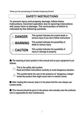
  • 1. I Thank you for purchasing LS Variable Frequency Drives! SAFETY INSTRUCTIONS To prevent injury and property damage, follow these instructions. Incorrect operation due to ignoring instructions will cause harm or damage. The seriousness of which is indicated by the following symbols. DANGER WARNING CAUTION This symbol indicates the possibility of death or serious injury This symbol indicates the possibility of injury or damage to property This symbol indicates the instant death or serious injury if you don’t follow instructions ■ The meaning of each symbol in this manual and on your equipment is as follows. This is the safety alert symbol. Read and follow instructions carefully to avoid dangerous situation. This symbol alerts the user to the presence of “dangerous voltage” inside the product that might cause harm or electric shock. ■ After reading this manual, keep it in the place that the user always can contact easily. ■ This manual should be given to the person who actually uses the products and is responsible for their maintenance.
  • 2. II WARNING n Do not remove the cover while power is applied or the unit is in operation. Otherwise, electric shock could occur. n Do not run the inverter with the front cover removed. Otherwise, you may get an electric shock due to high voltage terminals or charged capacitor exposure. n Do not remove the cover except for periodic inspections or wiring, even if the input power is not applied. Otherwise, you may access the charged circuits and get an electric shock. n Wiring and periodic inspections should be performed at least 10 minutes after disconnecting the input power and after checking the DC link voltage is discharged with a meter (below DC 30V). Otherwise, you may get an electric shock. n Operate the switches with dry hands. Otherwise, you may get an electric shock. n Do not use the cable when its insulating tube is damaged. Otherwise, you may get an electric shock. n Do not subject the cables to scratches, excessive stress, heavy loads or pinching. Otherwise, you may get an electric shock.
  • 3. III CAUTION n Install the inverter on a non-flammable surface. Do not place flammable material nearby. Otherwise, fire could occur. n Disconnect the input power if the inverter gets damaged. Otherwise, it could result in a secondary accident and fire. n Do not touch the inverter while the input power is applied or after removed. It will remain hot for a couple of minutes. Otherwise, you may get bodily injuries such as skin-burn or damage. n Do not apply power to a damaged inverter or to an inverter with parts missing even if the installation is complete. Otherwise, electric shock could occur. n Do not allow lint, paper, wood chips, dust, metallic chips or other foreign matter into the drive. Otherwise, fire or accident could occur. OPERATING PRECAUTIONS (1) Handling and installation ¨ Handle according to the weight of the product. ¨ Do not stack the inverter boxes higher than the number recommended. ¨ Install according to instructions specified in this manual. ¨ Do not open the cover during delivery. ¨ Do not place heavy items on the inverter. ¨ Check the inverter mounting orientation is correct. ¨ Do not drop the inverter, or subject it to impact. ¨ Use the ground impedance of 100ohm or less for 200 V Class and 10ohm or less for 400V class. ¨ Take protective measures against ESD (Electrostatic Discharge) before touching the pcb for inspection or installation. ¨ Use the inverter under the following environmental conditions:
  • 4. IV Ambient temp. - 10 ~ 40 ℃ (non-freezing) Relative humidity 90% RH or less (non-condensing) Storage temp. - 20 ~ 65 ℃ Location Protected from corrosive gas, combustible gas, oil mist or dust Altitude, Vibration Max. 1,000m above sea level, Max. 5.9m/sec2 (0.6G) or less Environment Atmospheric pressure 70 ~ 106 kPa (2) Wiring ¨ Do not connect a power factor correction capacitor, surge suppressor, or RFI filter to the output of the inverter. ¨ The connection orientation of the output cables U, V, W to the motor will affect the direction of rotation of the motor. ¨ Incorrect terminal wiring could result in the equipment damage. ¨ Reversing the polarity (+/-) of the terminals could damage the inverter. ¨ Only authorized personnel familiar with LS inverter should perform wiring and inspections. ¨ Always install the inverter before wiring. Otherwise, you may get an electric shock or have bodily injury. (3) Trial run ¨ Check all parameters during operation. Changing parameter values might be required depending on the load. ¨ Always apply permissible range of voltage to the each terminal as indicated in this manual. Otherwise, it could lead to inverter damage. (4) Operation precautions ¨ When the Auto restart function is selected, stay away from the equipment as a motor will restart suddenly after an alarm stop. ¨ The Stop key on the keypad is valid only when the appropriate function setting has been made. Prepare an emergency stop switch separately. ¨ If an alarm reset is made with the reference signal present, a sudden start will occur. Check that the reference signal is turned off in advance. Otherwise an accident could occur. ¨ Do not modify or alter anything inside the inverter. ¨ Motor might not be protected by electronic thermal function of inverter. ¨ Do not use a magnetic contactor on the inverter input for frequent starting/stopping of the inverter. ¨ Use a noise filter to reduce the effect of electromagnetic interference. Otherwise nearby electronic equipment may be affected.
  • 5. V ¨ In case of input voltage unbalance, install AC reactor. Power Factor capacitors and generators may become overheated and damaged due to potential high frequency noise transmitted from inverter. ¨ Use an insulation-rectified motor or take measures to suppress the micro surge voltage when driving 400V class motor with inverter. A micro surge voltage attributable to wiring constant is generated at motor terminals, and may deteriorate insulation and damage motor. ¨ Before operating unit and prior to user programming, reset user parameters to default settings. ¨ Inverter can easily be set to high-speed operations, Verify capability of motor or machinery prior to operating unit. ¨ Stopping torque is not produced when using the DC-Break function. Install separate equipment when stopping torque is needed. (5) Fault prevention precautions ¨ Provide a safety backup such as an emergency brake which will prevent the machine and equipment from hazardous conditions if the inverter fails. (6) Maintenance, inspection and parts replacement ¨ Do not conduct a megger (insulation resistance) test on the control circuit of the inverter. ¨ Refer to Chapter 8 for periodic inspection (parts replacement). (7) Disposal ¨ Handle the inverter as an industrial waste when disposing of it. (8) General instructions Many of the diagrams and drawings in this instruction manual show the inverter without a circuit breaker, a cover or partially open. Never run the inverter like this. Always place the cover with circuit breakers and follow this instruction manual when operating the inverter.
  • 6. VI (9) UL Marking 1. Short Circuit Rating “Suitable For Use On A Circuit Capable Of Delivering Not More Than Table1 RMS Symmetrical Amperes, 240V for 240V rated inverters, 480V for 480V rated inverters Volts Maximum,” Table 1. RMS Symmetrical Amperes for iS5 series. Model Rating SV008iS5-2, SV008iS5-4, SV015iS5-2, SV015iS5-4, SV022iS5-2, SV022iS5-4, SV037iS5-2, SV037iS5-4,SV055iS5-2, SV055iS5-4, SV075iS5-2, SV075iS5-4, SV110iS5-2, SV110iS5-4, SV150iS5-2, SV150iS5-4,SV185iS5-2, SV185iS5-4, SV220iS5-2, SV220iS5-4, SV3005iS5-2, SV300iS5-4, SV370iS5-2, SV370iS5-4 5,000A SV450iS5-2, SV450iS5-4, SV550iS5-2, SV550iS5-4, SV750iS5-4, 10,000A 2. OVERLOAD PROTECTION IOLT: IOLT(inverter Overload Trip) protection is activated at 150% of the inverter rated current for 1 minute and greater. OLT : Inverter shuts off its output when inverter output current exceeds its overload trip level for overload trip time. OLT is selected when FU1-56 is set to “Yes” and activated at 120% of FU1-57 [Motor rated current] for 60 sec set in FU1-58. 3. OVER SPEED PROTECTION “Not Provided With Overspeed Protection”. 4.Risk of Electric Shock More than one disconnect switch may be required to de-energize the equipment before servicing.
  • 7. 1 CONTENTS SAFETY INSTRUCTIONS I USER SELECTION GUIDE (IS5 SPECIFICATIONS).......................................................................................... 3 CHAPTER 1 - INSTALLATION........................................................................................................................ 6 1.1 Inspection..............................................................................................................................................................6 1.2 Environmental Conditions..................................................................................................................................6 1.3 Mounting................................................................................................................................................................6 1.4 Other Precautions................................................................................................................................................7 1.5 Dimensions ...........................................................................................................................................................8 1.6 Basic Wiring........................................................................................................................................................13 1.7 Power Terminals.................................................................................................................................................14 1.8 Control Terminals...............................................................................................................................................19 CHAPTER 2 - OPERATION ........................................................................................................................... 23 2.1 Parameter Groups..............................................................................................................................................23 2.2 LCD Keypad ........................................................................................................................................................24 2.3 7-Segment Keypad.............................................................................................................................................28 2.4 Operation Method...............................................................................................................................................32 2.5 Operating Example.............................................................................................................................................33 CHAPTER 3 - VARIOUS FUNCTION SETTING & DESCRIPTION............................................................. 38 3.1 Function Setting.................................................................................................................................................38 3.2 Operation Example.............................................................................................................................................46 CHAPTER 4 - QUICK-START PROCEDURES............................................................................................. 51 4.1 Operating using keypad....................................................................................................................................52 4.2 Operation using Control Terminals.................................................................................................................53 4.3 Operation using Keypad and Control Terminals ..........................................................................................54 CHAPTER 5 - PARAMETER LIST................................................................................................................. 56 5.1 Drive Group [DRV]..............................................................................................................................................56 5.2 Function 1 Group [FU1].....................................................................................................................................58 5.3 Function 2 Group [FU2].....................................................................................................................................60 5.4 Input/Output Group [I/O] ...................................................................................................................................64 5.5 External Group [EXT].........................................................................................................................................70 5.6 Communication Group [COM]..........................................................................................................................74 5.7 Application Group [APP]...................................................................................................................................75 5.8 Sub-Board Selection Guide According To Function....................................................................................77 CHAPTER 6 - PARAMETER DESCRIPTION ............................................................................................... 79 6.1 Drive group [DRV]..............................................................................................................................................79 6.2 Function 1 Group [FU1].....................................................................................................................................87 6.3 Function 2 Group [FU2].....................................................................................................................................99 6.4 Input/Output Group [I/O] .................................................................................................................................118 6.5 External Group [EXT].......................................................................................................................................136 6.6 Application Group [APP].................................................................................................................................145
  • 8. 2 CHAPTER 7 - OPTIONS ...............................................................................................................................153 7.1 Sub-A board.......................................................................................................................................................155 7.2 Sub-B Board......................................................................................................................................................157 7.3 Sub-C Board (Isolated) ....................................................................................................................................161 7.4 Communication option boards.......................................................................................................................163 7.5 Keypad................................................................................................................................................................165 7.6 DB Resistors......................................................................................................................................................167 7.7 DB (Dynamic Brake) Unit.................................................................................................................................175 CHAPTER 8 - TROUBLESHOOTING & MAINTENANCE..........................................................................181 8.1 Fault Display......................................................................................................................................................181 8.2 Fault Remedy.....................................................................................................................................................183 8.3 Troubleshooting................................................................................................................................................185 8.4 How to Check Power Components................................................................................................................186 8.5 Maintenance ......................................................................................................................................................187 8.6 Daily and Periodic Inspection Items..............................................................................................................188 APPENDIX A - FUNCTIONS BASED ON USE................................................................................................189 APPENDIX B - PARAMETERS BASED ON APPLICATION..........................................................................190 APPENDIX C- PERIPHERAL DEVICES...........................................................................................................192 DECLARATION OF CONFORMITY..................................................................................................................194
  • 9. 3 USER SELECTION GUIDE (iS5 SPECIFICATIONS) 230V Class (1 ~ 30HP) Model Number (SV xxx iS5 - 2) 008 015 022 037 055 075 110 150 185 220 HP 1 2 3 5 7.5 10 15 20 25 30Motor Rating1 kW 0.75 1.5 2.2 3.7 5.5 7.5 11 15 18.5 22 Capacity2 [kVA] 1.9 3.0 4.5 6.1 9.1 12.2 17.5 22.9 28.2 33.5 FLA [A] 5 8 12 16 24 32 46 60 74 88 Frequency 0 ~ 400 Hz (Sensorless Vector Control: 0 ~ 300Hz, Sensored Vector Control: 0 ~ 120 Hz) Output Ratings Voltage 200 ~ 230 V 3 Voltage 3 Phase, 200 ~ 230 V (± 10 %)Input Ratings Frequency 50 ~ 60 Hz (±5 %) Braking Circuit On Board On Board Optional (DB Resistor) Optional (DB Resistor) Max. Braking Torque 100% 100% 100% Max. Continuous Baking Time 5 seconds 5 seconds 15 seconds Dynamic Braking4 Max. Duty 3 % ED 2 % ED 20%, Continuous 10 % ED Weight [kg] 4.7 4.7 4.8 4.9 7.7 7.7 13.9 14.4 20 20 230V Class (40 ~ 75HP) Model Number (SV xxx iS5 - 2) 300 370 450 550 HP 40 50 60 75Motor Rating1 kW 30 37 45 55 Capacity2 [kVA] 46 55 68 84 FLA [A] 122 146 180 220 Frequency 0 ~ 400 Hz (Sensorless Vector Control: 0 ~ 300Hz, Sensored Vector Control: 0 ~ 120 Hz) Output Ratings Voltage 200 ~ 230 V 3 Voltage 3 Phase, 200 ~ 230 V (± 10 %)Input Ratings Frequency 50 ~ 60 Hz (±5 %) Braking Circuit Optional (Braking Unit, Resistor) Max. Braking Torque Max. Continuous Baking Time Dynamic Braking4 Max. Duty 20%, Continuous Weight [kg] 42 42 61 61 1 Indicates the maximum applicable capacity when using a 4-Pole LG motor. 2 Rated capacity (√3*V*I) is based on 220V for 200V class and 440V for 400V class. 3 Maximum output voltage will not be greater than the input voltage. Output voltage less than the input voltage may be programmed. 4 1~5 HP inverters have internal braking resistors as standard. 7.5~100 HP inverters utilize optional braking resistors.
  • 10. 4 460/480 V Class (1 ~ 30HP) Model Number (SV xxx iS5 - 4) 008 015 022 037 055 075 110 150 185 220 HP 1 2 3 5 7.5 10 15 20 25 30Motor Rating1 kW 0.75 1.5 2.2 3.7 5.5 7.5 11 15 18.5 22 Capacity2 [kVA] 1.9 3.0 4.5 6.1 9.1 12.2 18.3 22.9 29.7 34.3 FLA [A] 2.5 4 6 8 12 16 24 30 39 45 Frequency 0 ~ 400 Hz (Sensorless Vector Control: 0 ~ 300Hz, Sensored Vector Control: 0 ~ 120 Hz) Output Ratings Voltage 380 ~ 460 V, 380 ~ 480 V 3 Voltage 3 Phase, 380 ~ 460 V (± 10 %), 380 ~ 480 V (± 10 %) (Special type available from ‘2004)5Input Ratings Frequency 50 ~ 60 Hz (±5 %) Braking Circuit On Board On Board Optional (DB Resistor) Optional (DB Resistor) Max. Braking Torque 100% 100% 100% Max. Continuous Baking Time 5 seconds 5 seconds 15 seconds Dynamic Braking4 Max. Duty 3 % ED 2 % ED 20% Continuous 10 % ED Weight [kg] 4.7 4.7 4.8 4.9 7.7 7.7 13.9 14.4 20 20 460/480 V Class (40~100HP) Model Number (SV xxx iS5 - 4) 300 370 450 550 750 HP 40 50 60 75 100Motor Rating1 kW 30 37 45 55 75 Capacity2 [kVA] 45 56 68 82 100 FLA [A] 61 75 91 110 152 Frequency 0 ~ 400 Hz (Sensorless Vector Control: 0 ~ 300Hz, Sensored Vector Control: 0 ~ 120 Hz) Output Ratings Voltage 380 ~ 460 V, 380 ~ 480 V 3 Voltage 3 Phase, 380 ~ 460 V (± 10 %), 380 ~ 480 V(± 10 %) (Special type available from ‘2004) 6Input Ratings Frequency 50 ~ 60 Hz (±5 %) Braking Circuit Optional (Braking Unit, Resistor) Max. Braking Torque Max. Continuous Baking Time Dynamic Braking4 Max. Duty 20%, Continuous Weight [kg] 45 45 63 63 68 5 When applying input voltage of 507~528 V range, derate the load 10%. For example, when applying 507 V to 5.5kW inverters (rated current 12A), the max. rated output current would be 10.8A, calculated by multiplying 12A by 0.9 (90%). 6 Same as above.
  • 11. 5 Control Method V/F Control, Sensorless Vector Control, Sensored Vector Control (Velocity, Torque) Selectable Frequency Setting Resolution Digital Reference: 0.01 Hz (Below 100 Hz), 0.1 Hz (Over 100 Hz) Analog Reference: 0.03 Hz / 60 Hz Frequency Accuracy Digital: 0.01 % of Max. Output Frequency Analog: 0.1 % of Max. Output Frequency V/F Ratio Linear, Squared Pattern, User V/F Overload Capacity 150 % of Rated Current for 1 Min., 200% of Rated Current for 0.5 sec. (Characteristic is Inversely Proportional to Time) CONTROL Torque Boost Manual Torque Boost (0 ~ 15 %), Auto Torque Boost Operation Method Key / Terminal / Communication Operation Frequency Setting Analog: 0 ~ 10V / 4 ~ 20mA / Additional port for Sub-Board (0 ~ 10V) Digital: Keypad Start Signal Forward, Reverse Multi-Step Up to 8 Speeds can be Set (Use Multi-Function Terminal) Multi Step Accel/Decel Time 0 ~ 6,000 sec, Up to 4 Types can be Set and Selected for Each Setting (Use Multi- Function Terminal). Accel/Decel Pattern: Linear, U-Curve, S-Curve Emergency Stop Interrupts the Output of Inverter Jog Jog Operation Auto Operation Operates from Internal Sequence by Setting Multi-Function Terminal (5 Way * 8 Step) InputSignal Fault Reset Trip Status is Removed when Protection Function is Active Operating Status Frequency Detection Level, Overload Alarm, Stalling, Over Voltage, Under Voltage, Inverter Overheating, Running, Stop, Constant Speed, Inverter By-Pass, Speed Searching, Auto- Operation Step, Auto-Operation Sequence Fault Output Contact Output (30A, 30C, 30B) – AC250V 1A, DC30V 1A OutputSignal Indicator Choose 1 from Output Frequency, Output Current, Output Voltage, DC Voltage, Output Torque (Output Voltage: 0 ~ 10V) OPERATION Operation Function DC Braking, Frequency Limit, Frequency Jump, Second Function, Slip Compensation, Reverse Rotation Prevention, Auto Restart, Inverter By-Pass, Auto-Tuning, PID Control Inverter Trip Over Voltage, Under Voltage, Over Current, Fuse Open, Ground Fault, Inverter Overheating, Motor Overheating, Output Phase Open, Overload Protection, External Fault 1, 2, Communication Error, Loss of Speed Command, Hardware Fault, Option Fault, Overspeed, M/C Fail etc. Inverter Alarm Stall Prevention, Overload Alarm, Temperature Sensor Fault Protection Momentary Power Loss Auto Restart function activated when FU2-21 [Restart after fault reset] set to 1 (Yes) Operation Information Output Frequency, Output Current, Output Voltage, Frequency Value Setting, Operating Speed, DC Voltage, Output Torque Display Keypad Trip Information Indicates a Fault when the Protection Function activates, Retains Up to 5 Faults Ambient Temperature -10 °C ~ 40 °C (14 °F ~ 104 °F), CE Certification: 41 °F ~ 104 °F (5 °C ~ 40 °C) Storage Temperature -20 °C ~ 65 °C (-4 °F ~ 149 °F) Ambient Humidity Less Than 90 % RH Max. (Non-Condensing), CE Certification: 5 ~85% (Non-Condensing) Altitude - Vibration Below 1,000m or 3,300ft · Below 5.9m/sec2 (=0.6g) Environment Application Site No Corrosive Gas, Combustible Gas, Oil Mist, or Dust Cooling Method Forced Air Cooling
  • 12. 6 CHAPTER 1 - INSTALLATION 1.1 Inspection l Inspect the inverter for any damage that may have occurred during shipping. l Check the nameplate on the inverter. Verify the inverter unit is the correct one for the application. The numbering system for the inverter is as shown below. LS Inverter Motor Capacity Series Name Input Voltage 008: 1 HP 075: 10 HP 2: 200 ~ 230V (±10%) (50/60Hz) 015: 2 HP 110: 15 HP 4: 380 ~ 460V (±10%) (50/60Hz) UL Listed 022: 3 HP 150: 20 HP 4: 380 ~ 480V(±10%) (50/60Hz) 037: 5 HP 185: 25 HP 055: 7.5 HP 220: 30 HP N: Without Keypad O/E: UL Open/Enclosed Type 1 DB: Built-in DB Unit 1.2 Environmental Conditions l Verify ambient condition for the mounting location. - Ambient temperature should not be below 14ºF (-10ºC) or exceed 104ºF (40ºC). - Relative humidity should be less than 90% (non-condensing). - Altitude should be below 3,300ft (1,000m). l Do not mount the inverter in direct sunlight and isolate it from excessive vibration. l If the inverter is going to be installed in an environment with high probability of penetration of dust, it must be located inside watertight electrical boxes, in order to get the suitable IP degree. 1.3 Mounting l The inverter must be mounted vertically with sufficient horizontal and vertical space between adjacent equipment (A= Over 100mm, B= Over 50mm). However, A= Over 500mm and B= 200mm should be obtained for inverters with 40Hp and above. B A B A 008SV iS5 2 XXX U … (480)
  • 13. Chapter 1 – Installation 7 1.4 Other Precautions l Do not carry the inverter by the front cover. l Do not install the inverter in a location where excessive vibration is present. Be cautious when installing on presses or moving equipment. l The life span of the inverter is greatly affected by the ambient temperature. Install in a location where temperature are within permissible limits (- 10 ~ 40 ℃). l The inverter operates at high-temperatures - install on a non-combustible surface. l Do not install the inverter in high-temperature or high-humidity locations. l Do not install the inverter in a location where oil mist, combustible gas, or dust is present. Install the inverter in a clean location or in an enclosed panel, free of foreign substance. l When installing the inverter inside a panel with multiple inverters or a ventilation fan, use caution. If installed incorrectly, the ambient temperature may exceed specified limits. l Install the inverter using screws or bolts to insure the inverter is firmly fastened. Inverter GOOD (O) BAD (X) Inverter Cooling fan Panel Panel Inverter Inverter [When installing several inverters in a panel] Ventilating fan GOOD (O) BAD (X) [When installing a ventilating fan in a panel] UL Remark (File number: E124949): “Only intended for use in an enclosure with maximum surrounding air temperature of 45℃” or equivalent: Models SV022iS5-2/4, SV037iS5-2/4, SV055iS5-4 (not -2), SV075iS5-4 (not -2), SV110iS5-2/4, SV150iS5-2/4, SV185iS5-2/4 and SV220iS5-2/4.
  • 14. Chapter 1 – Installation 8 1.5 Dimensions n Frame # 1: 1 ~ 5 HP n Frame # 2: 7.5 ~ 10 HP mm (inches) Frame HP Model Number W1 W2 H1 H2 D1 1 SV008iS5-2/4 2 SV015iS5-2/4 3 SV022iS5-2/4 Frame # 1 5 SV037iS5-2/4 150 (5.91) 130 (5.12) 284 (11.18) 269 (10.69) 156.5 (6.16) 7.5 SV055iS5-2/4 Frame # 2 10 SV075iS5-2/4 200 (7.87) 180 (7.09) 355 (13.98) 340 (13.39) 182.5 (7.19)
  • 15. Chapter 1 – Installation 9 n Frame # 3: 15 ~ 20 HP n Frame # 4: 25 ~ 30 HP mm (inches) Frame HP Model Number W1 W2 H1 H2 D1 15 SV110iS5-2/4 Frame # 3 20 SV150iS5-2/4 250 (9.84) 230 (9.06) 385 (15.16) 370 (14.57) 201 (7.91) 25 SV185iS5-2/4 Frame # 4 30 SV220iS5-2/4 304 (11.97) 284 (11.18) 460 (18.11) 445 (17.52) 234 (9.21)
  • 16. Chapter 1 – Installation 10 n Frame # 5: 40~50HP STARVERT-iS5 mm (inches) Frame HP Model Number W1 W2 H1 H2 D1 40 SV300iS5-2/4 Frame # 5 50 SV370iS5-2/4 350 (13.78) 270 (10.63) 680 (28.77) 662 (26.06) 311 (12.25)
  • 17. Chapter 1 – Installation 11 n Frame # 6: 60~75HP(200V) STARVERT-iS5 mm (inches) Frame HP Model Number W1 W2 H1 H2 D1 60 SV450iS5-2 Frame # 6 75 SV550iS5-2 397 (15.63) 275 (10.83) 780 (30.71) 760.5 (29.94) 330 (12.99)
  • 18. Chapter 1 – Installation 12 n Frame # 7: 60~100HP (400V) mm (inches) Frame HP Model Number W1 W2 H1 H2 D1 60 SV450iS5-4 75 SV550iS5-4Frame # 7 100 SV750iS5-4 375 (14.76) 275 (10.83) 780 (30.71) 760.5 (29.94) 330 (12.99) STARVERT-iS5
  • 19. Chapter 1 – Installation 13 1.6 Basic Wiring 230/460V 50/60Hz U V W G ( ) R S T N1 DB Unit(Optional) 5 DB Resistor φ3 MCCB MC (Option) FX RX BX RST P1 P3 CM VR V1 I 5G (CM)6 + FM 5G (CM) 6 (N.O.) 30 A AXA AXC Output Frequency Meter (0~10V Linear) 2 P2 MOTOR Potentiometer (1 kohm, 1/2W) Speed signal Input3 Forward Run/Stop Reverse Run/Stop Inverter Disable Fault Reset Multi-functionInput 1 Multi-functionInput 2 Multi-functionInput 3 Common Terminal FactorySetting: ‘Speed-L’ ‘Speed-M’ ‘Speed-H’ Power supply for speed signal: + 12V, 10mA Speed signalinput: 0 ~ 10V Speed signalinput: 4 ~20mA (250ohm) Common for VR, V1, I Fault output relay less than AC250V, 1A less than DC30V, 1A Multi-functionoutput relay1 less than AC250V, 1A less than DC30V, 1A Factory setting: ‘Run’ Note) Main Circuit Terminals ControlCircuit Terminals. 1. The terminal configurationvaries depend on the model number. Please refer to the ‘1.7 Power terminals’. 2. Analog output voltage is adjustable up to 12V. 3. Analog speed command may be set by Voltage, Current orboth. 4. The Common Busbar between P1/L1and P2/L2 must be removed beforeinstalling DC Reactor. 5. 1 ~ 10 HP inverters havebuilt-in braking circuit. Braking resistorsareonlyincludedfor 1 ~ 5HP inverters. 15~30HP invertershave built-inDB unit. 15 ~ 100HP invertersneed optional braking unit and resistor. 6. In case of 40 HP or morethan,the terminal is CM terminalwhich has same electricpotentialwith Common Terminal. P2/ L21 P1/ L11 DC Bus Choke (Optional) 4 FM Dynamic Braking Unit (Optional) P N B1 B2 DC Bus Choke DB Resistor JOG Jog Shield (N.C.) 30 B 30 C Main Power Circuit Control Circuit
  • 20. Chapter 1 – Installation 14 1.7 Power Terminals n Type A Configuration: 1 ~ 5 HP (230/460/480V) R S T G N B1 B2 U V W n Type B Configuration: 7.5 ~ 10 HP (230/460/480V) R S T G P N B1 B2 U V W n Type C Configuration: 15 ~ 30 HP (230/460/480V) R S T G P1 P2 N U V W n Type C Configuration: 15 ~ 30 HP (230/460/480V), Built-in DBU model R S T G P1 B1 B2 U V W n Type D Configuration: 40~ 75 HP (230V), 40 ~ 100 HP (460/480V) R S T G U V W P1 P2 N * Jumper should be removed to connect a DC reactor Symbols Functions R S T AC Line Voltage Input (3 Phase, 200 ~ 230VAC or 380 ~ 460/480 VAC) G Earth Ground P Positive DC Bus Terminal DB Unit (P-P7) Connection Terminals (DB Unit may be added when more braking duty (More than 30%ED) is required) P1 P2 External DC Reactor (P1-P2) and DB Unit (P2-N) Connection Terminals N Negative DC Bus Terminal DB Unit (N-N8) Connection Terminal B1 B2 Dynamic Braking Resistor (B1-B2) Terminals for 1-30HP inverters U V W 3 Phase Power Output Terminals to Motor (3 Phase, 200 ~ 230VAC or 380 ~ 460/480 VAC) “Suitable for use on a circuit capable of delivering not more than 10,000 rms symmetrical amperes, 240 volts maximum for 230V class models and 480 volts maximum for 460V class models.” 7 This P terminal is provided on optional Dynamic Braking Unit. 8 This N terminal is provided on optional Dynamic Braking Unit. DB Resistor integrated
  • 21. Chapter 1 – Installation 15 1.7.1 Type A Configuration As standard on the iS5 inverter, this type of configuration has internal dynamic braking resistor of 3% ED. When an application requires more braking duty, an external dynamic braking resistor may be connected instead of the internal resistor. R S T G N B1 B2 U V W Figure 1 – Type A Dynamic Braking Resistor Installation 1.7.2 Type B Configuration A Dynamic Braking Resistor or a Dynamic Braking Unit may be added to iS5 series inverters that have a Type B configuration power terminal strip. R S T G P N B1 B2 U V W Figure 2 – Type B Dynamic Braking Resistor Installation R S T G P N B1 B2 U V W Figure 3 – Type B Additional Dynamic Braking Unit and Resistor Installation Motor Dynamic Braking Resistor 3 Phase Power Input Motor3 Phase Power Input Dynamic Braking Resistor Motor3 Phase Power Input Dynamic Braking Resistor Dynamic Braking Unit
  • 22. Chapter 1 – Installation 16 1.7.3 Type C Configuration A Dynamic Braking Unit or a DC Bus Choke or both of them may be added to iS5 series inverters that have a Type A Configuration power terminal strip. Jumper Between P1 and P2 Must Be Removed in Order to Install a DC Bus Choke. R S T G P1 P2 N U V W Figure 4 – Type C Dynamic Braking Unit, DC Bus Choke Installation R S T G P1 B1 B2 U V W Figure 5 – Type C Dynamic Braking Resistor 1.7.4 Type D Configuration R S T G U V W P1 P2 N Figure 6 – Type D Dynamic Braking Unit, DC Bus Choke Installation Motor3 Phase Power Input Dynamic Braking Unit DC Bus Choke (remove to wire DC Reactor Dynamic Braking Resistor Motor3 Phase Power Input Dynamic Braking Resistor Motor3 Phase Power Input Dynamic Braking Unit DB Resistor DC Bus Choke (remove to wire DC Reactor)
  • 23. Chapter 1 – Installation 17 1.7.5 Wiring Power Terminals n Wiring Precautions l The internal circuits of the inverter will be damaged if the incoming power is connected and applied to output terminals (U, V, W). l Use ring terminals with insulated caps when wiring the input power and motor wiring. l Do not leave wire fragments inside the inverter. Wire fragments can cause faults, breakdowns, and malfunctions. l For input and output, use wires with sufficient size to ensure voltage drop of less than 2%. l Motor torque may drop of operating at low frequencies and a long wire run between inverter and motor. l When more than one motor is connected to one inverter, total wire length should be less than 200m (656ft). Do not use a 3-wire cable for long distances. Due to increased leakage capacitance between wires, over-current protective feature may operate or equipment connected to the output side may malfunction. (But for products of less than 3.7kW, the wire length should be less than 50m(146ft).) In case of long wire length, it should be required to lower carrier frequency or use Micro Surge Filter. Length between Inverter and Motor Up to 50m Up to 100m More than 100m Allowable Carrier Frequency Less than 15kHz Less than 5kHz Less than 2.5kHz l Connect only recommended braking resistor between the B1 and B2 terminals. Never short B1 and B2 terminals. Shorting terminals may cause internal damage to inverter. l The main circuit of the inverter contains high frequency noise, and can hinder communication equipment near the inverter. To reduce noise, install line noise filters on the input side of the inverter. l Do not use power factor capacitor, surge killers, or RFI filters on the output side of the inverter. Doing so may damage these components. l Always check whether the LCD and the charge lamp for the power terminal are OFF before wiring terminals. The charge capacitor may hold high-voltage even after the power is disconnected. Use caution to prevent the possibility of personal injury. n Grounding l The inverter is a high switching device, and leakage current may flow. Ground the inverter to avoid electrical shock. Use caution to prevent the possibility of personal injury. l Connect only to the dedicated ground terminal of the inverter. Do not use the case or the chassis screw for grounding. l The protective earth conductor must be the first one in being connected and the last one in being disconnected. l As a minimum, grounding wire should meet the specifications listed below. Grounding wire should be as short as possible and should be connected to the ground point as near as possible to the inverter. Grounding wire Sizes, AWG (mm²) Inverter Capacity 200V Class 400VClass Below 3.7kW (5HP) 12 (3.5) 14 (2) 5.5~7.5kW (7.5~10HP) 10 (5.5) 12 (3.5) 11~15kW (15~20HP) 6 (14) 8 (8) 18.5~22kW (25~30HP) 4 (22) 6 (14) 30~37kW (40~50HP) 4 (22) 6 (14) 45~75kW (60~100HP) 2 (38) 4 (22) WARNING Normal stray capacitance between the inverter chassis and the power devices inside the inverter and AC line can provide a high impedance shock hazard. Do not apply power to the inverter if the inverter frame (Power terminal G) is not grounded.
  • 24. Chapter 1 – Installation 18 n Wires and Terminal Lugs Refer to the following table for wires, terminal lugs, and screws used to connect the inverter power input (R, S, T) and output (U, V, W). Input and motor output terminal blocks are intended only for use with ring type connectors. Wire10 Ring Terminals mm² AWGInverter Capacity Terminal Screw Size Screw Torque9 (Kgf·cm)/ lb-in R,S,T U,V,W R,S,T U,V,W R,S,T U,V,W 0.75~2.2kW(1~3HP) M3.5 7.1~12.2 / 6.2~10.6 2-4 2-4 2 2 14 14 3.7 kW (5HP) M3.5 7.1~12.2 / 6.2~10.6 2-4 2-4 3.5 3.5 12 12 5.5 kW (7.5HP) M4 7.1~12.2 / 6.2~10.6 5.5-5 5.5-5 5.5 5.5 10 10 7.5 kW (10HP) M4 7.1~12.2 / 6.2~10.6 14-5 8-5 14 8 6 8 11 kW (15HP) M5 24.5~31.8 / 21.2~27.6 14-5 14-5 14 14 6 6 15 kW (20HP) M5 24.5~31.8 / 21.2~27.6 22-6 22-6 22 22 4 4 18.5 kW (25HP) M6 30.6~38.2 / 26.6~33.2 38-8 38-8 30 30 2 2 22 kW (30HP) M6 30.6~38.2 / 26.6~33.2 38-8 38-8 38 30 2 2 30~37 kW (40~50HP) M8 61.2~91.8 / 53.1~79.7 60-8 60-8 60 60 2/0 2/0 200V Class 45~55 kW (60~75HP) M10 89.7~122.0 / 77.9~105.9 100-10 100-10 100 100 4/0 4/0 0.75~3.7 kW (1~5HP) M3.5 7.1~12.2 / 6.2~10.6 2-4 2-4 2 2 14 14 5.5 kW (7.5HP) M4 7.1~12.2 / 6.2~10.6 5.5-5 5.5-5 3.5 2 12 14 7.5 kW (10HP) M4 7.1~12.2 / 6.2~10.6 14-5 8-5 3.5 3.5 12 12 11 kW (15HP) M5 24.5~31.8 / 21.2~27.6 14-5 14-5 5.5 5.5 10 10 15 kW (20HP) M5 24.5~31.8 / 21.2~27.6 22-6 22-6 14 8 6 8 18.5 kW (25HP) M6 30.6~38.2 / 26.6~33.2 38-8 38-8 14 8 6 8 22 kW (30HP) M6 30.6~38.2 / 26.6~33.2 38-8 38-8 22 14 4 6 30~37 kW (40~50HP) M8 61.2~91.8 / 53.1~79.7 38-8 38-8 22 22 4 4 45~55 kW (60~75HP) M8 61.2~91.8 / 53.1~79.7 38-8 38-8 38 38 2 2 400V Class 75 kW (100HP) M8 61.2~91.8 / 53.1~79.7 60-8 60-8 60 60 2/0 2/0 n Power and Motor Connection R S T G N B1 B2 U V W 9 Apply the rated torque to terminal screws. Loose screws can cause of short circuit or malfunction. Tightening the screws too much can damage the terminals and cause a short circuit or malfunction. 10 Use copper wires only with 600V, 75℃ ratings. Motor3 Phase Power Input Power supply must be connected to the R, S, and T terminals. Connecting it to the U, V, and W terminals causes internal damages to the inverter. Arranging the phase sequence is not necessary. Motor should be connected to the U, V, and W terminals. If the forward command (FX) is on, the motor should rotate counter clockwise when viewed from the load side of the motor. If the motor rotates in the reverse, switch the U and V terminals.
  • 25. Chapter 1 – Installation 19 1.8 Control Terminals P1 P2 P3 FX RX NC VR V1 30A 30C 30B AXA AXC JOG CM CM BX RST I FM 5G Type Symbol Name Description P1, P2, P3 Multi-Function Input 1, 2, 3 Used for Multi-Function Input Terminal. (Factory default is set to “Multi-Step Frequency 1, 2, 3”.) FX Forward Run Command Forward Run When Closed and Stopped When Open. RX Reverse Run Command Reverse Run When Closed and Stopped When Open. JOG Jog Frequency Reference Runs at Jog Frequency when the Jog Signal is ON. The Direction is set by the FX (or RX) Signal. BX Emergency Stop When the BX Signal is ON the Output of the Inverter is Turned Off. When Motor uses an Electrical Brake to Stop, BX is used to Turn Off the Output Signal. When BX Signal is OFF (Not Turned Off by Latching) and FX Signal (or RX Signal) is ON, Motor continues to Run. RST Fault Reset Used for Fault Reset. StartingContactFunctionSelect CM Sequence Common Common Terminal for Contact Inputs. NC - Not Used. VR Frequency Setting Power (+12V) Used as Power for Analog Frequency Setting. Maximum Output is +12V, 100mA. V1 Frequency Reference (Voltage) Used for 0-10V Input Frequency Reference. Input Resistance is 20 KΩ. I Frequency Reference (Current) Used for 4-20mA Input Frequency Reference. Input Resistance is 250 Ω. Inputsignal Analogfrequencysetting 5G11 Frequency Setting Common Terminal Common Terminal for Analog Frequency Reference Signal and FM (For Monitoring). Analog FM Analog Output (0~12V) (For External Monitoring) Outputs One of the Following: Output Frequency, Output Current, Output Voltage, DC Link Voltage, and Torque. Default is set to Output Frequency. Maximum Output Voltage and Output Current are 0-12V and 1mA, 500Hz. 30A 30C 30B Fault Contact Output Activates when Protective Function is Operating. AC250V, 1A or less; DC30V, 1A or less. Fault: 30A-30C Closed (30B-30C Open) Normal: 30B-30C Closed (30A-30C Open) Outputsignal Contact AXA, AXC Multi-Function Output Relay Use After Defining Multi-Function Output Terminal. AC250V, 1A or less; DC30V, 1A or less. * Tightening torque of control terminal blocks TER 1 – 140 Kgf·cm/(93.5 in-lb) TER 2 – 8 Kgf·cm/(5.3 in-lb) 11 In case of above 30kW, it is CM and it has a same electric potential with sequence common terminal CM.
  • 26. Chapter 1 – Installation 20 1.8.1 Wiring Control Terminals n Wiring Precautions l CM and 5G terminals are insulated to each other. Do not connect these terminals with each other and do not connect these terminals to the power ground. Terminal 5G is indicated as CM from 30kW inverters and has the same potential as CM (Sequence Common Terminal). l Use shielded wires or twisted wires for control circuit wiring, and separate these wires from the main power circuits and other high voltage circuits. l It is recommended to use the cables of 1.25 mm²(22 AWG) for connection to the control circuit terminals. n Control Circuit Terminal l The control input terminal of the control circuit is ON when the circuit is configured to the current flows out of the terminal, as shown in the following illustration. CM terminal is the common terminal for the contact input signals. CAUTION Do not apply voltage to any control input terminals (FX, RX, P1, P2, P3, JOG, BX, RST, CM). 24 VDC FX RX CM Current Inverter Circuitry Resistor Resistor External Sequence
  • 27. Chapter 1 – Installation 21 1.8.2 Keypad Connection Connect keypad to the keypad connector as illustrated below. The LCD output will not be displayed on the keypad if the keypad is not connected properly. Control Board Control Terminal BlockRelay Output Terminal Block Keypad Connector (CN3) Sub-Board Connector Power Supply Input, Gate Drive Signal Output Connector Socket Option Board Connector Sub-Board Option Board
  • 28. Chapter 1 – Installation 22 Notes:
  • 29. 23 CHAPTER 2 - OPERATION The iS5 series inverter has seven parameter groups separated according to their applications as indicated in the following table. The iS5 series inverter provides two kinds of keypad. One is of 32-character alphanumeric LCD keypad and the other is of 7-Segment LED keypad. 2.1 Parameter Groups Parameter Group LCD Keypad (Upper left Corner) 7-segment Keypad (LED is lit) Description Drive Group DRV ‘DRV’ LED Command Frequency, Accel/Decel Time etc. Basic Parameters Function 1 Group FU1 ‘FU1’ LED Max. Frequency, Amount of Torque Boost etc. Basic Related Parameters Function 2 Group FU2 ‘FU2’ LED Frequency Jumps, Max./Min. Frequency Limit etc. Basic Application Related Parameters Input / Output Group I/O ‘I/O’ LED Multi-Function Terminal Setting, Auto Operation etc. Parameters needed for Sequence Operation Sub-Board Group EXT ‘EXT’ LED Displayed when Sub-Board is Installed. Option Group COM ‘I/O’ + ‘EXT’ LED Displayed when Option Board is Installed. Application Group APP ‘FU2’ + ‘I/O’ + ‘EXT’ LED Traverse, MMC (Multi-Motor Control), Draw etc. Application Related Parameters Refer to the function descriptions in chapter 6 for detailed description of each group.
  • 30. Chapter 2 - Operation 24 2.2 LCD Keypad LCD keypad can display up to 32 alphanumeric characters, and various settings can be checked directly from the display. The following is an illustration of the keypad. 32 character, back light, LCD display. The back light is adjustable. The Mode Button moves you through the seven program groups: DRV, FUN1, FUN2, I/O, (EXT), COM, and APP The Up and Down Arrows are used to move through and change data. Reverse Run Button. The Reverse Run LED blinks when the drive Accels or Decels. The Program Button is used to go into programming mode to change data. The Enter Button is used to enter changed data within a parameter. [SHIFT] This button is used to move cursor across display in programming mode. [ESC] This button is used to move the program code to DRV 00 form any program code. Forward Run Button The Forward Run LED blinks when the drive Accels or Decels. Stop Button is used to stop the drive from running. The Reset Button is used to reset Faults. The LED blinks when there is a fault.
  • 31. Chapter 2 - Operation 25 2.2.1 LCD Keypad Display DRV▶T/K 0.0 A 00 STP 0.00 Hz Displays Description 1) Parameter Group Displays the parameter group. There are DRV, FU1, FU2, I/O, EXT, COM, APP groups. 2) Run/Stop Source Displays the source of motor Run and Stop K: Run/Stop using FWD, REV buttons on keypad T: Run/Stop using control terminal input FX, RX O: Run/Stop via option board 3) Frequency Setting Source Displays the source of command frequency setting K: Frequency setting using keypad V: Frequency setting using V1 (0 ~10V) or V1 + I terminal I: Frequency setting using I (4 ~ 20mA) terminal U: Up terminal input when Up/Down operation is selected D: Down terminal input when Up/Down operation is selected S: Stop status when Up/Down operation is selected O: Frequency setting via Option board X: Frequency setting via Sub board J: Jog terminal input 1 ~ 8: Step frequency operation * During Auto operation, 2) and 3) display the ‘sequence number/step’. 4) Output Current Displays the Output Current during operation. 5) Parameter Code Displays the code of a group. Use the ▲(Up), ▼(Down) key to move through 0~99 codes. 6) Operating Status Displays the operation information. STP: Stop Status FWD: During Forward operation REV: During Reverse operation DCB: During DC Braking LOP: Loss of Reference from Option Board (DPRAM fault) LOR: Loss of Reference from Option Board (Communication network fault) LOV: Loss of Analog Frequency Reference (V1: 0~10V) LOI: Loss of Analog Frequency Reference (I: 4~20mA) LOS: Loss of Reference from Sub-Board 7) Drive Output Frequency Command Frequency Displays the Output Frequency during run. Displays the Command Frequency during stop. 2) Run/Stop Source 3) Frequency Setting Source 4) Output Current 7) Drive Output Frequency During Run, Command Frequency During Stop6) Operating Status 5) Parameter Code 1) Parameter group
  • 32. Chapter 2 - Operation 26 2.2.2 Procedure for Setting Data (LCD Keypad) 1. Press [MODE] key until the desired parameter group is displayed. 2. Press [▲] or [▼] keys to move to the desired parameter code. If you know the desired parameter code, you can set the code number of each parameter group in “Jump code”, except DRV group. 3. Press [PROG] key to go into the programming mode, the cursor starts blinking. 4. Press [SHIFT/ESC] key to move the cursor to the desired digit. 5. Press [▲] or [▼] keys to change the data. 6. Press [ENT] key to enter the data. The cursor stops blinking. n Note: Data cannot be changed when: 1) The parameter is not adjustable during the inverter is running. (Refer to the function table in Chapter 5) or 2) Parameter Lock function is activated in FU2-94 [Parameter Lock].
  • 33. Chapter 2 - Operation 27 2.2.3 Parameter Navigation (LCD Keypad) The parameter group moves directly to DRV group by pressing [SHIFT/ESC] key in any parameter code. DRV▶T/K 0.0 A 00 STP 0.00 Hz FU1▶ Jump code 00 1 FU2▶ Jump code 00 30 MODE ◀ FU1▶Run prohibit 03 None FU2▶ Last trip-1 01 ------- I/O▶ V1 filter 01 10 ms DRV▶ Dec. time 02 20.0 sec FU1▶Acc. pattern 05 Linear FU2▶ Last trip-2 02 ------- I/O▶ V1 volt x1 02 0.00 V FU1▶Dec. pattern 06 Linear FU2▶ Last trip-3 03 ------- I/O▶ V1 freq y1 03 0.00 Hz DRV▶ Freq mode 04 KeyPad-1 FU1▶ Stop mode 07 Decel FU2▶ Last trip-4 04 ------- I/O▶ V1 volt x2 04 10.00 V DRV▶ Step freq-1 05 10.00 Hz FU1▶ DcSt value 08 50 % FU2▶ Last trip-5 05 ------- I/O▶ V1 freq y2 05 60.00 Hz FU1▶ Stall Level 60 150 % FU2▶ Para. lock 94 0 I/O▶ Way1 / 2D 60 Forward MODE MODEMODE MODE I/O▶ Jump code 00 1 ▶ MODE ◀ ▶ MODE ◀ ▶ MODE ◀ ▶ MODE ◀ ▶ ◀ ▶ ◀ ▶ ◀ ▶ ◀ ▶ ◀ ▶ ◀ ▶ ◀ ▶ ◀ ▶ ◀ ▶ ◀ ▶ ◀ ▶ ◀ ▶ ◀ ▶ ◀ ▶ ◀ ▶ ◀ ▶ ◀ ▶ ◀ ▶ DRV▶ Drive mode 03 Fx/Rx-1 DRV▶ Fault 12 ------- DRV▶ Acc. time 01 10.0 sec MODE MODE MODE MODEMODEMODEMODE MODE MODE MODE MODE MODEMODEMODEMODE MODE MODE MODE MODE ◀ ▶ Drive Group FU1 Group FU2 Group I/O Group . . . . . . . . . . . .
  • 34. Chapter 2 - Operation 28 2.3 7-Segment Keypad * Parameter Group Display LEDs – When parameter code is located on DRV 20, DRV 21, DRV 22 and DRV 23, respectively by rotating the encoder knob, the parameter group display LEDs of DRV, FUN1, FUN2, I/O, EXT blink. LED Parameter Group Description DRV Drive Group Lit in Drive group. FU1 FUNCTION 1 Group Blinks when the parameter code is located on DRV 20 [FUN1]. Lit when FUNCTION 1 group is selected. FU2 FUNCTION 2 Group Blinks when the parameter code is located on DRV 21 [FUN2]. Lit when FUNCTION 2 group is selected. I/O Input/Output Group Blinks when the parameter code is located on DRV 22 [I/O]. Lit when Input/Output group is selected. EXT Sub-Board Group Blinks when the parameter code is located on DRV 23 [EXT]. Lit when Sub-Board group is selected. This group appears only when a Sub-Board is installed. I/O + EXT Option Group Blinks when the parameter code is located on DRV 24 [EXT]. Lit when Option group is selected. This group appears only when an Option Board is installed. FU2 + I/O + EXT Application Group Blinks when the parameter code is located on DRV 25 [FUN2]. 7-segment display Encoder knob Used to move you through parameter groups and parameter code. Also, used to change data by rotating knob. Program Button is used to go into programming mode to change data. Enter Button is used to enter the changed data. The LED blinks during programming mode. [SHIFT] This button is used to move cursor across display in programming mode. [ESC] This button is used to move the program code to DRV 00 from any program code. Run Button is used to run the drive. The motor direction is set in DRV 13. The Run LED blinks when the drive Accels or Decels. Stop Button is used to stop the drive from running. Reset Button is used to reset Faults. The LED blinks when there is a fault. * Parameter Group Display LEDs.
  • 35. Chapter 2 - Operation 29 2.3.1 7-Segment Keypad Display Display Description 1) Parameter Group Displays the parameter groups of DRV, FU1, FU2, I/O, EXT, COM, APP groups. Each LED is lit when its parameter group is selected and blinks when the parameter code is located on DRV 20, DRV 21, DRV 22, DRV 23, DRV 24, and DRV 25. 2) Parameter Code and Operating Status Displays the code of a group. Rotate the encoder knob to move through 0 ~ 99 codes. Displays the operation information. [First digit] F: Forward operation r: Reverse operation [Second digit] d: DC Braking J: Jog Terminal Input 1~8: Step Frequency Input (Displays the Step of the Auto operation) [Two digits] - mark the reference is lost. PL: Loss of Reference from the Option Board (DPRAM fault) rL: Loss of Reference from the Option Board (Communication network fault) vL: Loss of Analog Frequency Reference (V1: 0~10V) IL: Loss of Analog Frequency Reference (I: 4~20mA) XL: Loss of Reference from the Sub-Board 3) Output Frequency, Command Frequency Displays the Output Frequency during run. Displays the Command Frequency during stop. DRV FU1 I/OFU2 EXT 1) Parameter Group 3) Output Frequency during run, Command Frequency during stop 2) Parameter Code and Operating Status
  • 36. Chapter 2 - Operation 30 2.3.2 Procedure for Setting Data (7-Segment Keypad) n In DRV Group: 1. Rotate the encoder knob until the desired parameter code is displayed. 2. Press [PROG/ENT] key to go into the programming mode, then the display blinks. 3. Press [SHIFT/ESC] key to move the cursor to the desired digit. 4. Rotate the encoder knob to change the data. 5. Press [PROG/ENT] key to enter the changed data. n In FUN1 Group: 1. Rotate the encoder knob until parameter code ‘20’ is displayed in drive group. 2. Press [PROG/ENT] key to go into the FUN1 group. 3. Rotate the encoder knob until the desired parameter code is displayed. 4. Press [PROG/ENT] key to go into the programming mode, then the display blinks. 5. Press [SHIFT/ESC] key to move the cursor to the desired digit. 6. Rotate the encoder knob to change the data. 7. Press [PROG/ENT] key to enter the changed data. n In FUN2 Group: 1. Rotate the encoder knob until parameter code ‘21’ is displayed in drive group. 2. Go to step 2 of ‘In FUN1 Group’ above, and follow the rest procedure. n In I/O Group: 1. Rotate the encoder knob until parameter code ‘22’ is displayed in drive group. 2. Go to step 2 of ‘In FUN1 Group’ above, and follow the rest procedure.
  • 37. Chapter 2 - Operation 31 2.3.3 Parameter Navigation (7-Segment Keypad) The parameter group moves directly to DRV group by pressing [SHIFT/ESC] key in any parameter code. DRV FU1 I/OFU2 EXT DRV FU1 I/OFU2 EXT DRV FU1 I/OFU2 EXT DRV FU1 I/OFU2 EXT DRV FU1 I/OFU2 EXT DRV FU1 I/OFU2 EXT DRV FU1 I/OFU2 EXT DRV FU1 I/OFU2 EXT DRV FU1 I/OFU2 EXT PROG ENT DRV FU1 I/OFU2 EXT DRV FU1 I/OFU2 EXT DRV FU1 I/OFU2 EXT Encoder Knob FU1 Group DRV Group FU2 Group I/O Group PROG ENT PROG ENT SHIFT ESC PROG ENT
  • 38. Chapter 2 - Operation 32 2.4 Operation Method The iS5 has several operation methods as shown below. Operation Method Function Function Setting Operation using Keypad Run/Stop command and frequency are set only through the keypad. DRV 03: Keypad DRV 04: Keypad-1 or -2 Operation using Control Terminals Closing FX or RX terminal performs Run/Stop. Frequency reference is set through V1 or I or V1+I terminal. DRV 03: Fx/Rx-1 or -2 DRV 04: V1 or I or V1+I Run/Stop is performed by the keypad. Frequency reference is set through the V1 or I or V1+I terminal. DRV 03: Keypad-1 or -2 DRV 04: V1 or I or V1+I Operation using both Keypad and Control Terminals Closing FX or RX terminal performs Run/Stop. Frequency reference is set through the keypad. DRV 03: Fx/Rx-1 or -2 DRV 04: Keypad-1 or -2 Operation using Option Board Operation using option board. The iS5 has five option boards and three sub-boards. Option Boards: RS485, Device-Net, F-Net, ProfiBus and ModBus Sub-Boards: Sub-A Board, Sub-B Board, Sub-C Board (Please refer to ‘Chapter 7 - Options’ for more information.)
  • 39. Chapter 2 - Operation 33 2.5 Operating Example 2.5.1 Operation via Control terminal + Keypad 1. Check the LCD display when Power ON. Otherwise, change the setting indicated above. 2. Turn the FX (or RX) terminal ON. Then FWD (or REV) LED will be lit. 3. When setting the Ref. Freq to 60 Hz using PROG/ENT/SHIFT, ▲ keys, motor will rotate at 60Hz. FWD (or REV) LED will be flickering during Acceleration/ Deceleration. 4. Turn Fx (or Rx) terminal Off. Then Stop LED will be lit. DRV▶T/K 0.0 A 00 STP 0.00Hz DRV▶T/K 0.0 A 00 FWD 0.00Hz DRV▶ Cmd. freq 00 0.00Hz DRV▶ Cmd. freq 00 60.00Hz DRV▶T/K 5.0 A 00 FWD 60.00Hz Note) To enable Run/Stop via keypad & Freq setting via control terminal… Setting: DRV-03 [Drive Mode (Run/Stop method)] = 0 (Keypad) DRV-04 [Frequency Mode (Freq. setting method)] = 2 (V1) Setting: DRV-03 [Drive Mode (Run/Stop method)] = 1 (Fx/Rx-1) DRV-04 [Frequency Mode (Freq. setting method)] = 0 (Keypad-1) l With above setting, Freq setting via terminal & Run/Stop via Keypad disabled DRV▶T/K 0.0 A 00 STP 60.00Hz
  • 40. Chapter 2 - Operation 34 Operation Example (1) Freq Setting via Keypad + Run/Stop via Terminal (FX/RX) [Operation condition] -. Control mode: V/F control -. Ref. Frequency: 50[Hz] setting via keypad -. Accel/Decel time: Accel – 10 [Sec], Decel – 20 [Sec] -. Drive mode: Run/Stop via FX/RX terminal [Wiring] R S T G U V W B1 B2 FX RX BX RST JOG P1 P2 P3 CM VR V1 5G FM 5G 30A 30C 30B AXA AXC IM 3P AC input Potentiometer 1[kohm],1/2W S/W Step Parameter setting Code Description 1 Control Mode Selection FU2-39 Set it to 0 {V/F}. 2 Drive Mode DRV-3 Set it to 1 Fx/Rx-1. 3 Frequency Mode DRV-4 Set it to 0 Keypad-1. 4 50[Hz] freq command setting DRV-0 Set freq command 50[Hz] via Keypad. 5 Accel/Decel time DRV-2 DRV-3 Set Accel time to 10 [Sec] in DRV-2. Set Decel time to 20 [Sec] in DRV-3. 6 Terminal FX Motor starts to rotate in Forward direction at 50Hz with Accel time 10 [sec] when FX terminal is turned ON. Motor decelerates to stop with Decel time 25[sec] when FX terminal is turned OFF. 7 Terminal RX When RX terminal is turned ON motor starts to rotate in Reverse direction at 50[Hz] with Accel time 10 [Hz]. When it is OFF, motor decelerates to stop with Decel time 20 [Sec].
  • 41. Chapter 2 - Operation 35 2.5.2 Operation via Control Terminal 1. Check the LCD display when Power ON. Otherwise, change the setting indicated above. 2. Turn the FX (or RX) terminal ON. Then FWD (or REV) LED will be lit. 3. Set the frequency using V1 (Potentiometer). Output freq (60Hz)., Rotating direction (FWD or REV) and output current (5A) will be displayed on the LCD. 4. Output freq value is decreasing when turning the potentiometer counterclockwise. Inverter output stops at 0.00Hz and motor is stopped. 5. Turn FX (or RX) terminal OFF. Setting: DRV-03 [Drive Mode (Run/Stop method)] = 1 (Fx/Rx-1) DRV-04 [Frequency Mode (Freq. setting method)] = 2 (V1) DRV▶T/V 0.0 A 00 STP 0.00Hz DRV▶T/V 0.0 A 00 FWD 0.00Hz DRV▶T/V 5.0 A 00 FWD 60.00Hz DRV▶T/V 0.0 A 00 FWD 0.00Hz DRV▶T/V 0.0 A 00 STP 0.00Hz
  • 42. Chapter 2 - Operation 36 Operation Example (2) Analog Voltage Input (V1) + Operation via Terminal (FX/RX) [Operation condition] -. Control mode: V/F control -. Reference Frequency: 50[Hz] analog input via V1 (Potentiometer) -. Accel/Decel time: Accel – 10 [Sec], Decel – 20 [Sec] -. Drive mode: Run/Stop via FX/RX terminal [Wiring] R S T G U V W B1 B2 FX RX BX RST JOG P1 P2 P3 CM VR V1 5G FM 5G 30A 30C 30B AXA AXC IM 3P AC input Potentiometer 1[kohm],1/2W S/W Step Parameter setting Code Description 1 Control Mode Selection FU2-39 Set it to 0 {V/F}. 2 Drive Mode DRV-3 Set it to 1 Fx/Rx-1. 3 Frequency Mode DRV-4 Set it to 2 V1 Analog input. 4 50[Hz] freq command setting DRV-0 Set freq command 50[Hz] via V1(potentiometer). 5 Accel/Decel time DRV-2 DRV-3 Set Accel time to 10 [Sec] in DRV-2. Set Decel time to 20 [Sec] in DRV-3. 6 Terminal FX Motor starts to rotate in Forward direction at 50Hz with Accel time 10 [sec] when FX terminal is turned ON. Motor decelerates to stop with Decel time 20[sec] when FX terminal is turned OFF. 7 Terminal RX When RX terminal is turned ON motor starts to rotate in Reverse direction at 50[Hz] with Accel time 10 [Hz]. When it is OFF, motor decelerates to stop with Decel time 20 [Sec].
  • 43. Chapter 2 - Operation 37 2.5.3 Operation via Keypad 1. Check the LCD display when Power ON. Otherwise, change the setting indicated above. 2. Set the Ref. Freq to 60 Hz using PROG/ENT/SHIFT, ▲ keys. Setting freq is displayed during stop. 3. When pressing FWD/REV key, motor starts running and output freq and output current are displayed. 4. Press STOP/RESET key. Then motor decelerates to stop. Setting freq 60Hz is displayed. DRV▶K/K 0.0 A 00 STP 0.00Hz Setting: DRV-03 [Drive Mode (Run/Stop method)] = 0 (Keypad) DRV-04 [Frequency Mode (Freq. setting method)] = 0 (Keypad-1) DRV▶K/K 0.0 A 00 STP 60.00Hz DRV▶K/K 5.0 A 00 FWD 60.00Hz DRV▶K/K 0.0 A 00 STP 60.00Hz
  • 44. 38 CHAPTER 3 - VARIOUS FUNCTION SETTING & DESCRIPTION 3.1 Function Setting 3.1.1 Basic function parameter setting It is the basic function setting. All settings are factory defaults unless users make change. It is recommended to use factory setting value unless the parameter change is necessary. 1) Common parameter setting The following table shows common parameter setting that should be checked before use but making change does not affect inverter control type. Parameter Name Code Description Motor Selection FU2-30 Selects motor and voltage rating suitable to the desired inverter. Motor parameters FU2-31 ~ 36 Basic parameter value setting when selecting the motor rating. ☞ Note: If there is any discrepancy between parameter preset value and the actual motor parameter value, change the parameter value according to the actual motor. Drive Mode DRV-3 Operation via Keypad, Fx/Rx-1, Fx/Rx-2 setting Frequency or Torque Mode DRV-4 Frequency/Torque setting parameter It automatically changes to torque mode when FU2 39- [Control mode] is set to Sensorless_T, Vector_TRQ. Accel/Decel time setting DRV-1, DRV-2 Accel/Decel time setting 2) V/f control FU2-39 [Control mode] is set to 0 (V/F) as factory setting. Operation via V/F control can be performed after common parameter settings are done and the followings are set. Parameter Name Code Description Starting freq. FU1-22 Set frequency to start the motor. Torque boost FU1-26 Manual or Auto torque boost settable in this parameter Torque boost value FU1-27, FU1-28 If FU1-26 [torque boost] is set to manual, user sets the desired value and the direction in code FU1-27 and 28.
  • 45. Chapter 3 – Function Settings 39 3) V/F + PG control If FU2-39 [control mode] is set to V/F with PG (encoder) feedback using SUB-B board, the control type is automatically changed to V/F + PG. The following parameters should be set accordingly to enable PG feedback using SUB-B board. Parameter Name Code Description Usage of Pulse Input Signal EXT-12 Defines the use of pulse input signal with SUB-B mounted. This parameter should be set to 1 {Feed-back}. Pulse Signal Input Selection EXT-15 Three types of input signal settable; (A+B), A, -(A+B) Encoder Pulse Number EXT-16 Defines the number of encoders of the motor. P-Gain for ‘Sub-B’ I-Gain for ‘Sub-B’ EXT-22, EXT-23 PI gains for PI controller during PG operation Slip Frequency for ‘Sub-B’ Board EXT-24 Set as a percent of FU2-32 [Rated Motor Slip]. 4) Slip compensation Operation is done via Slip compensation if FU2-39 is set to 1 {Slip compen}. This control keeps motor speed constant regardless of load change. 5) Auto-tuning of motor constant This parameter enables auto-tuning of the motor constants. If set to 1 {All mode}, tuning type varies according to what control mode is set in [FU2-39]. Auto-tuning can be done in two ways – one is motor non-rotation mode, the other is motor rotation mode. ① Auto-tuning by non-rotation mode: Rs+Lsigma ② Auto-tuning by rotation mode: All, Enc Test, Tr Before performing Auto-tuning, set motor rating, motor parameter in common setting and select the desired control mode in FU2-39 [control mode selection]. However, when auto-tuning parameters related to encoder, detail functions settings of vector control should be pre-defined. If Enc Test, Tr and control mode are set to vector control, Sub-B board should be mounted. Parameter Name Code Description Auto-tuning FU2-40 No, All, Rs+Lsigma, Enc Test, Tr Parameter value display FU2-34, FU2-41 ~ 44 Tuned value monitoring (No-load current, stator/rotor resistance, leakage inductance, rotor filter time constant)
  • 46. Chapter 3 – Function Settings 40 FU2-40 Description No Motor constants calculation disabled. All All constants can be measured in this code but different constants are tuned according to control mode; For V/F, Slip compen, Sensorless_S, Sensorless_T: (No-load current, stator resistance, leakage inductance, stator inductance available) ☞ Note: Only no-load current can be calculated during V/F and Slip compensation. For Vector_SPD, Vector_T: (No-load current, stator resistance, leakage inductance, stator inductance, encoder test, rotor filter time constant) Rs+Lsigma Calculates stator resistance, leakage inductance. Enc Test Calculates the encoder status. Tr Calculates Rotor filter time constant. 6) Sensorless vector control Set FU2-39 to 2 {Sensorless_S} or 3 {Sensorless_T} to enable Sensorless vector control. It is strongly recommended to perform Auto-tuning for Sensorless before starting Sensorless control in order to maximize performance. Two types of Sensorless vector control are available; Sensorless_S or Sensorless_T. Parameter Name Code Description Control mode selection FU2-39 Select Sensorless_S or Sensorless_T. P, I gain for sensorless control FU2-45, FU2-46 Set gain for Sensorless_S control. Starting freq FU1-22 Starting freq of the motor 7) Vector control Set FU2-39 to 4 {Vector_SPD} or 5 {Vector_TRQ} to enable Vector control. Encoder should be installed to the motor with Sub-B board in the inverter to start this control. Parameter Name Code Description Usage of Pulse Input Signal EXT-12 Defines the method of pulse input with SUB-B board mounted. Vector control setting is valid only after this parameter is set to 1 {Feed-back}. Pulse Input Signal Selection EXT-15 3 types of pulse input: (A+B), A, -(A+B) Encoder Pulse Number EXT-16 Enters the pulse number of encoder in the motor. Before selecting Vector control mode, encoder setting should be done as indicated above. If the parameter value of actual motor is set in common setting, execute Auto-tuning before selecting vector control mode.
  • 47. Chapter 3 – Function Settings 41 Parameter Name Code Description Control Mode Selection FU2-39 Selects Vector_SPD or Vector_TRQ. Forward/ Reverse Torque Limit EXT-27, EXT-28 Sets the FWD/REV limit to the torque current. P-Gain/ I-Gain for (Sensored) Vector_SPD EXT-25, EXT-26 Sets P/I Gain for Vector_SPD control. Speed Limit setting EXT-50, EXT-51 EXT-52, EXT-53 Sets speed limit for Vector_TRQ. Zero Speed Detection Level/ Bandwidth EXT-54, EXT-55 Sets on/off of Multi-function output terminal relay when the motor speed reaches to 0. Torque Detection Level/Bandwidth EXT-56, EXT-57 Detects certain level/bandwidth of Torque. 3.1.2 Advanced function setting SV-iS5 inverter features advanced function parameters to maximize efficiency and performance of the motor. It is recommended to use as factory setting unless parameter value change is necessary. 1) V/F control Parameter Name Code Description V/F Pattern FU1-29 Use it according to load characteristics. If User V/F is selected, user can select the optimum output V/F characteristic for the application and load characteristics in [FU1-30]~[FU1-37]. Dwell operation FU2-07 FU2-08 Used to output torque in an intended direction. Inverter stops acceleration for the preset [FU2-08] Dwell time while running at Dwell frequency [FU2-07] and starts acceleration at commanded frequency. Setting [FU2-08] Dwell time to 0 disable the Dwell operation. Frequency jump FU2-10 FU2-11~16 When it is desired to avoid resonance attributable to the natural frequency of a mechanical system, these parameters allow resonant frequencies to be jumped. Up to three areas can be set, with the jump frequencies set to either the top or bottom point of each area. To enable the function, set [FU2-10] to ‘Yes’ and set the value in [FU2- 11]~[FU2-16]. S-curve Accel/Decel pattern FU2-17/ FU2-18 This pattern has an effect on the prevention of cargo collapse on conveyor etc and reduction in an acceleration/ deceleration shock.
  • 48. Chapter 3 – Function Settings 42 2) Sensorless vector control Related parameters for starting in Sensorless vector control when FU2-39 [Control Mode Selection] is set to 2 {Sensorless_S} Status Code Description FU1-14 Pre-excitation time setting When starting I/O12~14 EXT2~4 Multi-function input terminal P1- P6 define 3) Vector control [Vector_SPD, Vector_TRQ] Related parameters for running/ stopping in Vector control when FU2-39 [Control Mode Selection] is set to 4 {Vector_SPD} Status Code Description FU1-14 Pre-excitation time setting When starting I/O12~14 EXT2~4 Multi-function input terminal P1- P6 define Pre-excitation current FU1-16 Pre-excitation current setting FU1-15 Hold time at a stop setting When stopping FU1-7 Stopping method selection This parameter can limit the over-speeding (motor running above limit level) of the motor when FU2-39 [Control mode] is set to 5 {Vector_TRQ}. Parameter Name Code Description Speed limit level / bias / gain EXT-50 ~ EXT-53 Function to limit the speed and change reference torque value according to speed 4) Parameters to monitor motor and inverter status Parameter Name Code Description Output current/ motor speed DRV-8 ~ 9 Displays output current and motor rpm. DC link voltage DRV-10 Displays DC link voltage. User display selection (Voltage and watt) DRV-11 FU2-73 Either output voltage or power selected in FU2-73 is displayed in DRV11. Reference/ Feedback frequency display DRV-15 Displays Reference/ Feedback frequency display. Fault display DRV-14 Displays the current inverter fault.
  • 49. Chapter 3 – Function Settings 43 5) Parameter initialize Parameter Name Code Description Software version FU2-79 Displays the inverter software version. Parameter Read/Write/Initialize/Lock FU2-91 FU2-92 FU2-93 FU2-94 [FU2-91], [FU2-92]: Copying parameters from other inverter [FU2-93]: Initializing parameters to factory setting values [FU2-94]: Parameter write disabled ☞ Note: Motor parameters (FU2-31~37, FU2-41~44) are back to factory setting once Parameter Read/Writie is executed. 6) Protection & Trip level setting Parameter Name Code Description Electronic thermal FU1-50 FU1-51 FU1-52 FU1-53 Protection of the motor from overheating without the use of external thermal relay. Refer to parameter descriptions for more detail. Overload alarm and trip FU1-54, FU1-55 FU1-56, FU1-57 FU1-58 Warning alarm outputs and displays the trip message when overcurrent above the threshold value keeps on. Stall prevention FU1-59, FU1-60 Set the output current level at which the output freq will be adjusted to prevent the motor from stoping due to over- current etc. it activates during accel/ constant speed/ decel to prevent the motor stall. 7) Starting / Accel/ Decel / Stopping pattern setting Parameter Name Code Description Accel/Decel pattern FU1-05 FU1-06 5 types of Accel/ Decel pattern: ‘Linear’, ‘S-curve’, ’U- curve’, ’Minimum’, ‘Optimum’ settable according to appplication and load characteristic. If ‘S-curve’ is selected, the desired value of [FU2-17], [FU2-18] is settable. Stopping method FU1-07 3 types of stopping method ‘Decel’, ‘DC-brake’, ‘Free-run’ selectable. If ‘DC-brake’ is selected, the desired value of [FU1-8]~ [FU1-11] is settable. Starting DC Injection Braking Voltage/ Time FU1-12 FU1-13 The motor accelerates after the preset [FU1-12] for the preset [FU1-13] is applied. Starting DC injection braking is inactive when the value is set to 0 in control mode other than V/F and Slip compensation. Frequency Limit selection FU1-23 FU1-24 FU1-25 Limits the active frequency. Inverter operates at the freq range between upper freq limit [FU1-25] and bottom freq limit [FU1-24] and higher/ lower freq value is entered, it is automatically replaced by limit value. Setting range: [FU1- 20] Maximum freq to [FU1-21] Base freq. Dynamic braking FU2-75 FU2-76 Select the DB resistor mode when the regenerative load. Is connected. Refer to DBU manual for more details.
  • 50. Chapter 3 – Function Settings 44 8) Operation-starting method Parameter Name Code Description Starting method FU2-20 FU2-21 FU2-26 FU2-27 Motor starting method: [FU2-20]: Power-on run, [FU2-21] Restart after Fault Reset, [FU2-26] Number of Auto Restart Attempt [FU2-27] Delay Time Before Auto Restart See parameter description for more details. Speed Search Selection FU2-22 FU2-23 FU2-24 FU2-25 Speed search function is available during Accel, trip, instant power failure, restart after fault reset and auto restart. See parameter description for more details. 3.1.3 Application function setting 1) PID operation The inverter can be used to exercise process control, e.g. flow rate, air volume or pressure via PID feedback control. Parameter Name Code Description PID control setting FU2-41~ FU2-60 Parameters for PID control setting 2) Jog and Multi-speed operation Parameter Name Code Description Multi function input terminal setting I/O-12 ~14 EXT2 ~ 4 If I/O-12 ~14 are set to Speed-H, Speed-M, Speed-L, multi- speed operation up to speed 7 is available. Filter time constant for input terminal I/O-17 Effective for eliminating noise in the freq. setting circuit Speed reference value DRV-05 ~ 7 I/O-21 ~ I/O-24 Speed reference value for each step setting Accel/Decel time setting for each step I/O-25 ~ 38 Accel/Decel time for each step setting Jog freq. I/O-20 Jog freq for jog operation setting Speed-H Speed-M Speed-L JOG Speed Signal Parameter value 0 0 0 0 Speed 0 DRV-00 X X X 1 Jog freq. I/O-20 0 0 1 0 Speed –1 DRV-05 0 1 0 0 Speed –2 DRV-06 0 1 1 0 Speed –3 DRV-07 1 0 0 0 Speed –4 I/O-21 1 0 1 0 Speed –5 I/O-22 1 1 0 0 Speed –6 I/O-23 1 1 1 0 Speed –7 I/O-24
  • 51. Chapter 3 – Function Settings 45 3) Auto sequence operation If I/O-50 [Auto (Sequence) Operation selection] is set to 1 {Auto-A} or 2 {Auto-B}, up to 5 sequences can be set with max of 8 steps (speed) in each sequence. Therefore, max 40 operating steps can be made. Two different types of auto sequence (A, B) operation are available. Parameter Name Code Description Auto operation setting I/O-50 ~ 84 Sets 8 steps and 5 sequences (Max). 4) 2nd motor operation 2nd function setting is required to run the two motors by one inverter by exchange. If the terminal defined for 2nd function signal input is turned ON, 2nd motor operation is valid. Parameter Name Code Description Multi-function input terminals setting I/O-12 ~14 EXT2 ~ 4 2nd motor operation is available with Multi-function input terminals P1 ~ P3 or P4 ~ 6 set to 7 {2nd Func}. Parameter setting for 2nd motor operation FU2-81 ~ FU2-90 Setting parameters necessary to operate 2nd motor such as base freq., Accel/Decl time, Stall. 5) Energy-saving operation FU1-39 [Energy Save Level] tunes the inverter output voltage to minimize the inverter output voltage during during constant speed operation. Appropriate for energy-saving applications such as fan, pump and HVAC.
  • 52. Chapter 3 – Function Settings 46 3.2 Operation Example Operation Example (1) V/F Control + Analog Voltage Input (V1) + Operation via Terminal (FX/RX) [Operation condition] -. Control mode: V/F control -. Frequency command: 50[Hz] analog input via V1 terminal -. Accel/Decel time: Accel – 15 [Sec], Decel – 25 [Sec] -. Drive mode: Run/Stop via FX/RX terminal [Wiring] R S T G U V W B1 B2 FX RX BX RST JOG P1 P2 P3 CM VR V1 5G FM 5G 30A 30C 30B AXA AXC IM 3P AC input Potentiometer 1[kohm],1/2W S/W Step Parameter setting Code Description 1 Control Mode Selection FU2-39 Set it to 0 {V/F}. 2 Drive Mode DRV-3 Set it to Fx/Rx-1. 3 Frequency Mode DRV-4 Set V1 Analog input value in frequency mode. 4 50[Hz] freq command setting DRV-0 Set freq command 50[Hz] via V1 (potentiometer). 5 Accel/Decel time DRV-2 DRV-3 Set Accel time to 15 [Sec] in DRV-2. Set Decel time to 25 [Sec] in DRV-3. 6 Terminal FX Motor starts to rotate in Forward direction at 50Hz with Accel time 15 [sec] when FX terminal is turned ON. Motor decelerates to stop with Decel time 25[sec] when FX terminal is turned OFF. 7 Terminal RX When RX terminal is turned ON motor starts to rotate in Reverse direction at 50[Hz] with Accel time 15 [Hz]. When it is OFF, motor decelerates to stop with Decel time 25 [Sec].
  • 53. Chapter 3 – Function Settings 47 Operation example (2) (V/F + PG) Control + Operation (Run/Stop) via Keypad [Operation condition] -. Control mode: V/F + PG control -. Frequency command: 50[Hz] Digital input via Keypad -. Accel time: 15[sec], Decel time: 25 [sec] -. Drive mode: Run/Stop via Keypad -. Wiring block diagram when an Open Collector- type encoder is used. [Wiring] AOC R S T G U V W B1 B2 FX RX BX RST JOG P1 P2 P3 CM VR V1 5G IM 3P AC Input BOC A+ A- B+ B- FBA FBB GND EEncoder GND +5V +5V VCC VCC Keypad connector MODE PROG ENT REV SHIFT ESC STOP RESET FWD LC-200 Sub-B Power Supply 12V-15V DC Step Parameter setting Code Description 1 Control Mode Selection FU2-39 Set it to 0 {V/F}. 2 Drive mode DRV-3 Set it to 0 {KeyPad}. 3 Frequency Mode DRV-4 Set it to 0 {KeyPad-1}. 4 Digital Command Frequency setting DRV-0 Press PROG key on the keypad to set 50 Hz 5 Accel/Decel time setting DRV-2 DRV-3 Accel time: set DRV-2 to 15[sec] Decel time: set DRV-3 to 25[sec] 6 Sub-B board setting EXT-12 EXT-15 EXT-16 Set EXT-12 [Usage of Pulse Input Signal] to 1 {Feed-back} and set EXT-15 and EXT-16 after checking encoder rating on the nameplate. 7 FWD Operation Motor runs at 50[Hz] in forward direction with Accel time 15[sec] by PG control when pressing FWD key on the keypad. Motor decelerates to stop with Decel time 25[sec] when pressing Stop key. 8 REV Operation Motor runs at 50[Hz] in reverse direction with Accel time 15[sec] by PG control when pressing REV key on the keypad. Motor decelerates to stop with Decel time 25[sec] when pressing Stop key.
  • 54. Chapter 3 – Function Setting 48 Operation Example (3) 2nd motor operation [Operation condition] -. Control mode: V/F control -. 1st motor + 2nd motor Operation by exchange using [2nd Func] (Values can be set differently) -. Frequency command: Using Multi-step operation (1st motor --- 50[Hz] as main speed, 2nd motor --- 20[Hz] with P1 terminal set as multi- step operation) -. Accel/Decel time: 1st motor --- Accel time: 15[Sec], Decel time: 25 [Sec] 2nd motor --- Accel time: 30[Sec], Decel time: 40 [Sec] -. Drive mode: Run/Stop via FX/RX [Wiring] R S T G U V W B1 B2 FX RX BX RST JOG P1 P2 P3 CM VR V1 5G FM 5G 30A 30C 30B AXA AXC IM 1st motor 3P AC input IM 2nd motor 1st /2nd motor Switch-over FX RX BX CM 1st / 2nd motor select Step Parameter setting Code Description 1 Control Mode Selection FU2-39 Set it to 0 {V/F}. 2 Drive mode DRV-3 Set it to Fx/Rx-1. 3 Frequency Mode setting DRV-4 Set it to 0 {keypad-1}. 1st motor freq setting 4 Multi-function input terminal P2 I/O-13 Set P2 to 2nd Func. 5 Multi-function input terminal P1 I/O-12 Set P1 to Speed-L. 2nd motor freq setting 6 Freq setting for 1st motor DRV-0 Set it to 50[Hz]. 7 Accel/Decel time setting for 1st motor DRV-1, DRV-2 Set Accel/Decel time to 15[sec]/25[sec]. 8 Freq setting for 2nd motor DRV-5 Set it to 10[Hz]. 9 Accel/Decel time setting for 2nd motor FU2-81/82 Set Accel/Decel time to 30[sec]/50[sec]. 10 1st motor operation Set it as main motor by turning P1, P2, output relay OFF. Run the motor in FWD/REV direction using FX/RX terminal. 11 2nd motor operation Set 2nd motor parameters by turning terminal P2 ON. Change the freq setting to 20[Hz] by turning terminal P1 ON. Change 2nd motor terminal by turning output relay ON. Run the motor in FWD/REV direction by terminal FX/RX.
  • 55. Chapter 3 – Function Settings 49 Operation Example (4) Sensorless_S Control + Multi-speed operation + Analog output (FM) [Operation condition] -. Control mode: Sensorless Speed control -. Frequency command: Multi-function input from SUB-A and 8 step speed operation (Multi-speed 7 + Jog freq 1) -. Accel time: 5 [Sec], Decel time: 5 [Sec] -. Drive mode: Run/Stop and speed output via terminal FX/RX [Wiring] I/O-20 Speed 4 I/O-21 Speed 5 I/O-22 Speed 6 I/O-23 Speed 7 Multi-speed freq setting range DRV-00 Speed 0 DRV-05 Speed 1 DRV-06 Speed 2 DRV-07 Speed 3 ON ON ON ON ON ON ON ON ON ON SPD 0 SPD 1 SPD 2 SPD 3 SPD 4 SPD 5 SPD 6 SPD 7 JOG P4 P5 P6 JOG FX RX Output freq [Hz] Output freq meter 0 -10 V, Pulse R S T G U V W B1 B2 FX RX BX RST JOG P1 P2 P3 CM FM 5G 30C 30B AXA AXC IM S/W P4 CN5 P5 P6 CM Sub - A S/W FM 30A Step Parameter setting Code Description 1 Control Mode Selection FU2-39 Set it to Sensorless_S. 2 Drive mode DRV-3 Set it to FX/RX-1. 3 Multi-function input EXT-2 ~ 4 Set P3, P4, P5 to Speed-L, Speed-M, Speed-H. 4 FM (Frequency Meter) Output Selection I/O-40 Set it to Frequency output. 5 FM Output Adjustment I/O-41 Output V = 10V x output freq x output gain (ex100%) / (Max freq x 100) 6 Terminal FX Motor runs in forward direction at the set freq via P3, 4, 5 if Fx terminal is ON. Motor decelerates to stop with Decel time 5 [sec] if FX terminal is OFF. 7 Terminal RX Motor runs in reverse direction at the set freq via P3, 4, 5 if RX terminal is ON. Motor decelerates to stop with Decel time 5 [sec] if RX terminal is OFF.
  • 56. Chapter 3 – Function Setting 50 Operation Example (5) Vector_SPD Control [Operation condition] -. Control Mode: Vector_SPD Control, -. Encoder specification: Pulse number (1024), Line Drive type -. Freq command: set 55[Hz] via KPD-1 -. Accel/Decel time: Accel – 15 [sec], Decel – 25 [sec], -. Drive mode: Run/Stop via terminal FX/RX [Wiring] AOC R S T G U V W B1 B2 FX RX BX RST JOG P1 P2 P3 CM VR V1 5G IM 3P AC Input BOC A+ A- B+ B- FBA FBB GND EEncoder GND +5V +5V VCC VCC Keypad connector MODE PROG ENT REV SHIFT ESC STOP RESET FWD LC-200 Sub-B Step Parameter setting Code Description 1 Motor related setting FU2-30 ~ FU2-36 Set motor capacity, pole number, rated voltage/ current/slip and efficiency. 2 Encoder related setting EXT-12 EXT-15 EXT-16 Set EXT-12 to Feed-back, EXT-1 to A+B. Set EXT-16 to 1024. 3 Control Mode Selection Fu2-39 Encoder related setting should be done before setting control mode to Vector_SPD. 4 Auto-tuning FU2-40 Auto-tuning starts when set to ALL. Read the encoder manual carefully to clear the error if the messages ” Enc Err”, “Enc Rev” are displayed. 5 Keypad input setting DRV-4 DRV-0 Set DRV-4 to KPD-1 and press the Prog key to set 55 [Hz] in Drv- 0. 6 Accel/Decel time setting DRV-2 DRV-3 Accel time: set 15[Sec] Decel time: set 25[Sec] 7 Drive mode DRV-3 Set it to FX/RX-1. 8 FX/RX terminal Motor runs with Accel time 15 [Sec] at 55 [Hz] if FX/RX terminal is turned ON. Motor decelerates to stop with Decel time 25 [Sec] if FX/RX terminal is turned OFF.
  • 57. 51 CHAPTER 4 - QUICK-START PROCEDURES These Quick-Start Up instructions are for those applications where: l The user wants to get the iS5 inverter started quickly. l The factory-preset values are suitable for the user application. The factory-preset values are shown on the ‘Chapter 5 - Parameter List’. The iS5 inverter is configured to operate a motor at 60Hz (base frequency). If the application requires coordinated control with other controllers, it is recommended the user become familiar with all parameters and features of the inverter before applying AC power. 1. Mounting the inverter (mount the inverter as described in ‘1.3 Mounting’) l Install in a clean, dry location. l Allow a sufficient clearance around top and sides of inverter. l The ambient temperature should not exceed 40°C (104°F). l If two or more inverters are installed in an enclosure, add additional cooling. 2. Wiring the inverter (connect wiring as described in ‘1.7 Power Terminals’) l AC power should be turned OFF. l Verify the AC power matches the nameplate voltage. l Remove the screw on the bottom front cover of the inverter for terminal board access (For terminal board access on 15~ 30HP inverters you must disconnect the keypad cable from the inverter and fully remove the cover).
  • 58. Chapter 4 – Quick start procedures 52 4.1 Operating using keypad 1. Apply AC power. 2. LCD: Press [▲] key three times. 7-Seg: Rotate the encoder knob until ‘03’ is displayed. 3. LCD: Press [PROG] key. 7-Seg: Press [PROG/ENT] key. 4. LCD: Press [▼] key one time. 7-Seg: Rotate the encoder knob left. 5. LCD: Press [PROG] key. 7-Seg: Press [PROG/ENT] key. 6. Press [PROG/ENT] key. 7. LCD: Press [PROG] key. 7-Seg: Press [PROG/ENT] key. 8. LCD: Press [SHIFT/ESC] key and press [▲] key to increase the command frequency. 7-Seg: Rotate the encoder knob right to change the command frequency. The changing digit moves by pressing the [SHIFT/ESC] key. 9. LCD: Press [ENT] key to save the data. 7-Seg: Press [PROG/ENT] key to save the data. 10. LCD: Press [FWD] or [REV] key to start motor. 7-Seg: Press [RUN] key to start motor. 11. Press [STOP/RESET] key to stop motor. LCD Display 7-Segment Display DRV►T/K 0.0 A 00 STP 0.00Hz DRV► Cmd. freq 00 0.00Hz DRV► Cmd. freq 00 60.00Hz DRV►K/K 0.0 A 00 STP 60.00Hz DRV► Drive mode 03 Fx/Rx-1 DRV► Drive mode 03 Fx/Rx-1 DRV► Drive mode 03 Keypad DRV► Drive mode 03 Keypad The PROG/ENT LED turned ON. The PROG/ENT LED is turned ON. The DRV LED is ON. The DRV LED is turned ON. DRV►K/K 0.0 A 00 STP 0.00Hz The PROG/ENT LED is turned ON. The PROG/ENT LED is turned ON. The FWD or REV LED starts blinking. The RUN LED starts blinking. To change the motor running direction, change DRV 13 to ‘1’. The STOP/RESET LED starts blinking. The STOP/RESET LED starts blinking.
  • 59. Chapter 4 – Quick start procedures 53 4.2 Operation using Control Terminals 1. Install a potentiometer on terminals V1, VR, 5G and connect wiring as shown below. 2. Apply AC power. 3. Confirm that the DRV 03 is set at ‘Fx/Rx-1’. 4. LCD: Press [▲] key to move DRV 04. 7-Seg: Rotate encoder knob until ‘04’ is displayed. 5. LCD: Press [PROG] key. 7-Seg: Press [PROG/ENT] key. 6. LCD: Press [▲] key and set at ‘V1’. 7-Seg: Rotate encoder knob and set at ‘2’. 7. LCD: Press [ENT] key. 7-Seg: Press [PROG/ENT] key. 8. Press [SHIFT/ESC] key. 9. Set the frequency by rotating the potentiometer. 10. Close the FX or RX contact to run the motor. 11. Open the FX or RX contact to stop the motor. LCD Display 7-Segment Display DRV►T/K 0.0 A 00 STP 0.00Hz The DRV LED is ON. DRV► Drive mode 03 Fx/Rx-1 DRV► Freq mode 04 Keypad-1 DRV► Freq mode 04 Keypad-1 DRV► Freq mode 04 V1 DRV► Freq mode 04 V1 DRV►T/V 0.0 A 00 STP 0.00Hz DRV►T/V 0.0 A 00 STP 60.00Hz The PROG/ENT LED is turned ON. The PROG/ENT LED is turned ON. The PROG/ENT LED is turned OFF. The FWD or REV LED starts blinking. The RUN LED starts blinking. The STOP/RESET LED starts blinking. The STOP/RESET LED starts blinking. 1 ㏀, 1/2 W P1 P2 JOG CM P3 FX RX NC CM BX RST I VR VI FM 5G
  • 60. Chapter 4 – Quick start procedures 54 4.3 Operation using Keypad and Control Terminals 4.3.1 Frequency set by External Source and Run/Stop by Keypad 1. Install a potentiometer on terminals V1, VR, 5G and connect wiring as shown below left. When a ‘4 to 20mA’ current source is used as the frequency reference, use terminals I and 5G as shown below. 2. Apply AC power. 3. LCD: Press [▲] key to move DRV 03. 7-Seg: Rotate encoder knob until ‘03’ is displayed. 4. LCD: Press [PROG] key. 7-Seg: Press [PROG/ENT] key. 5. LCD: Press [▲] key one time. 7-Seg: Rotate encoder knob and set at ‘0’. 6. LCD: Press [ENT] key. 7-Seg: Press [PROG/ENT] key. 7. Confirm that the DRV 04 is set at ‘V1’. 8. Press [SHIFT/ESC] key. Set the frequency by rotating the potentiometer. 9. LCD: Press [FWD] or [REV] key. 7-Seg: Press [RUN] key. P1 P2 JOG CM P3 FX RX NC CM BX RST I VR VI FM 5G 4 to 20mA signal 1 ㏀, 1/2 W P1 P2 JOG CM P3 FX RX NC CM BX RST I VR VI FM 5G DRV 04 must be set at V1. DRV 04 must be set at I. DRV►T/K 0.0 A 00 STP 0.00Hz The DRV LED is ON. DRV► Drive mode 03 Fx/Rx-1 DRV► Drive mode 03 Fx/Rx-1 The PROG/ENT LED is turned ON. DRV► Drive mode 03 Keypad The PROG/ENT LED is turned ON. DRV► Drive mode 03 Keypad The PROG/ENT LED is turned OFF. DRV► Freq mode 04 V1 The PROG/ENT LED is turned ON. DRV►T/V 0.0 A 00 STP 60.00Hz The FWD or REV LED starts blinking. The RUN LED starts blinking. To change the motor running direction, change DRV 13 to ‘1’.
  • 61. Chapter 4 – Quick start procedures 55 4.3.2 Frequency set by Keypad and Run/Stop by External Source. 1. Connect wiring as shown below. 2. Apply AC power. 3. Confirm that the DRV 03 is set at ‘Fx/Rx-1’. 4. Confirm that the DRV 04 is set at ‘Keypad-1’. 5. Press [SHIFT/ESC] key. 6. LCD: Press [PROG] key. 7-Seg: Press [PROG/ENT] key. 7. LCD: Set the frequency using [SHIFT/ESC] and [▲] key. 7-Seg: Set the frequency by rotating the encoder knob. 8. LCD: Press [ENT] key to save the data. 7-Seg: Press [PROG/ENT] key to save the data. 9. Close the FX or RX contact to run the motor. 10. Open the FX or RX contact to stop the motor. LCD Display 7-Segment Display P1 P2 JOG CM P3 FX RX NC CM BX RST I VR VI FM 5G DRV►T/K 0.0 A 00 STP 0.00Hz DRV► Drive mode 03 Fx/Rx-1 DRV► Freq mode 04 Keypad-1 DRV►T/K 0.0 A 00 STP 0.00Hz DRV► Cmd. freq 00 0.00Hz DRV►T/V 0.0 A 00 STP 60.00Hz The FWD or REV LED starts blinking. DRV► Cmd. freq 00 60.00Hz The FWD or REV LED starts blinking. The DRV LED is ON. The PROG/ENT LED is turned ON. The PROG/ENT LED is turned ON. The RUN LED starts blinking. The RUN LED starts blinking.
  • 62. 56 CHAPTER 5 - PARAMETER LIST 5.1 Drive Group [DRV] Keypad Display Setting Range Code Description LCD 7-Segment LCD 7-Segment Units Factory Default Adj. During Run Page DRV-0011 Command Frequency or Command Torque (Output Frequency/ Torque during motor run, Reference Frequency/ Torque during motor stop) Output Current (LCD) Cmd. freq or Cmd. Trq F or r (DRV-13) 0 to FU1-20 (Max. freq) 0.01 0.00 [Hz] Yes 79 DRV-01 Acceleration Time Acc. time 01 0 to 6000 0.1 20.0 [sec] Yes 80 DRV-02 Deceleration Time Dec. time 02 0 to 6000 0.1 30.0 [sec] Yes 81 Keypad 0 Fx/Rx-1 1DRV-03 Drive Mode (Run/Stop Method) Drive mode 03 Fx/Rx-2 2 - Fx/Rx-1 No 81 Keypad-1 0 Keypad-2 1 V1 2 I 3 DRV-04 Frequency Mode or Torque Mode (Frequency/Torque setting Method) Freq mode or Torque mode 04 V1+I 4 - Keypad-1 No 82 DRV-05 Step Frequency 1 Step freq-1 05 10.00 [Hz] DRV-06 Step Frequency 2 Step freq-2 06 20.00 [Hz] DRV-07 Step Frequency 3 Step freq-3 07 0 to FU1-20 (0 to Max. freq) 0.01 30.00 [Hz] Yes 83 DRV-08 Output Current Current 08 Load Current in RMS - [A] - 84 DRV-09 Motor Speed Speed 09 Motor Speed in rpm - [rpm] - 84 DRV-10 DC link Voltage DC link Vtg 10 DC Link Voltage inside inverter - [V] - 84 DRV-11 User Display Selection User disp 11 Selected in FU2-73 (User Disp) - - - 84 DRV-12 Fault Display Fault 12 - - - None nOn - 84 0 [Forward] DRV-13 Motor Direction Set Not displayed in LCD keypad 13 Not available 1 [reverse] - 0 Yes 85 DRV-14 Target/Output Frequency Display Tar/Out Freq. 14 - - - 0.00 [Hz] Yes 85 DRV-1512 Reference/Feedback Frequency Display Ref/Fbk Freq. 15 - - - 0.00 [Hz] Yes 85 Hz disp 0 DRV-16 Speed Unit Selection Hz/Rpm Disp 16 Rpm disp 1 - - Yes 85 DRV-20 FU1 Group Selection 20 85 DRV-21 FU2 Group Selection 21 85 DRV-22 I/O Group Selection 22 85 DRV-2313 EXT Group Selection Not displayed in LCD keypad 23 Not available Press [PROG/ENT] key - 1 Yes 85 11 The speed unit is changed to [%] when FU2-39 is set to ‘Sensorless_T’ or ‘Vector_TRQ’. 12 Code DRV-15 appears only when FU2-47 is set to ‘Yes’. 13 Code DRV-23 through DRV-24 appears only when a Sub-Board or an Option Board is installed.
  • 63. Chapter 5 - Parameter List 57 Keypad Display Setting Range Code Description LCD 7-Segment LCD 7-Segment Units Factory Default Adj. During Run Page DRV-24 COM Group Selection 24 - 1 Yes 85 DRV-25 APP Group Selection 25 - 1 Yes 85
  • 64. Chapter 5 - Parameter List 58 5.2 Function 1 Group [FU1] Keypad Display Setting Range Code Description LCD 7-Segment LCD 7-Segment Units Factory Default Adj. During Run Page FU1-00 Jump to Desired Code # Jump code Not displayed 1 to 99 Not available 1 1 Yes 87 None 0 Forward Prev 1FU1-03 Run Prevention Run Prev. 03 Reverse Prev 2 - None No 87 Linear 0 S-curve 1 U-curve 2 Minimum 3 FU1-05 Acceleration Pattern Acc. pattern 05 Optimum 4 - Linear No 87 Linear 0 S-curve 1 U-curve 2 Minimum 3 FU1-06 Deceleration Pattern Dec. pattern 06 Optimum 4 - Linear No 87 Decel 0 DC-brake 1FU1-07 Stop Mode Stop mode 07 Free-run 2 - Decel No 88 FU1-0814 DC Injection Braking Frequency DcBr freq 08 FU1-22 to 60 [Hz] 0.01 5.00 [Hz] No FU1-09 DC Injection Braking On-delay Time DcBlk time 09 0 to 60 [sec] 0.01 0.1 [sec] No FU1-10 DC Injection Braking Voltage DcBr value 10 0 to 200 [%] 1 50 [%] No FU1-11 DC Injection Braking Time DcBr time 11 0 to 60 [sec] 0.1 1.0 [sec] No 89 FU1-12 Starting DC Injection Braking Voltage DcSt value 12 0 to 200 [%] 1 50 [%] No FU1-13 Starting DC Injection Braking Time DcSt time 13 0 to 60 [sec] 0.1 0.0 [sec] No 90 FU1-14 Pre-excitation Time PreExTime 14 0 to 60 [sec] 0.1 1.0 [sec] No 90 FU1-15 Hold Time Hold Time 15 0 to 1000 [ms] 1 1000 [ms] No 91 FU1-16 Pre-excitation Current Flux Force 16 100 to 500 [%] 0.1 100.0 [%] No 91 FU1-20 Maximum Frequency Max freq 20 40 to 400 [Hz] 0.01 60.00 [Hz] No FU1-21 Base Frequency Base freq 21 30 to FU1-20 0.01 60.00 [Hz] No FU1-22 Starting Frequency Start freq 22 0.01 to 10 [Hz] 0.01 0.50 [Hz] No 91 No 0 FU1-23 Frequency Limit selection Freq limit 23 Yes 1 - No No FU1-2415 Low Limit Frequency F-limit Lo 24 0 to FU1-25 0.01 0.50 [Hz] Yes FU1-25 High Limit Frequency F-limit Hi 25 FU1-24 to FU1-20 0.01 60.00 [Hz] No 92 Manual 0 FU1-26 Manual/Auto Torque Boost Selection Torque boost 26 Auto 1 - Manual No 92 14 Code FU1-08 through FU1-11 appears only when FU1-07 is set to ‘DC-Brake’. 15 Code FU1-24 through FU1-25 appears only when FU1-23 is set to ‘Yes’.
  • 65. Chapter 5 - Parameter List 59 Keypad Display Setting Range Code Description LCD 7-Segment LCD 7-Segment Units Factory Default Adj. During Run Page FU1-27 Torque Boost in Forward Direction Fwd boost 27 0 to 15 [%] 0.1 2.0 [%] No FU1-28 Torque Boost in Reverse Direction Rev boost 28 0 to 15 [%] 0.1 2.0 [%] No Linear 0 Square 1FU1-29 Volts/Hz Pattern V/F pattern 29 User V/F 2 - Linear No 93 FU1-3016 User V/F – Frequency 1 User freq 1 30 0 to FU1-20 0.01 15.00 [Hz] No FU1-31 User V/F – Voltage 1 User volt 1 31 0 to 100 [%] 1 25 [%] No FU1-32 User V/F – Frequency 2 User freq 2 32 0 to FU1-20 0.01 30.00 [Hz] No FU1-33 User V/F – Voltage 2 User volt 2 33 0 to 100 [%] 1 50 [%] No FU1-34 User V/F – Frequency 3 User freq 3 34 0 to FU1-20 0.01 45.00 [Hz] No FU1-35 User V/F – Voltage 3 User volt 3 35 0 to 100 [%] 1 75 [%] No FU1-36 User V/F – Frequency 4 User freq 4 36 0 to FU1-20 0.01 60.00 [Hz] No FU1-37 User V/F – Voltage 4 User volt 4 37 0 to 100 [%] 1 100 [%] No 94 FU1-38 Output Voltage Adjustment Volt control 38 40 to 110 [%] 0.1 100.0 [%] No 94 FU1-39 Energy Save Level Energy save 39 0 to 30 [%] 1 0 [%] Yes 94 No 0 FU1-50 Electronic Thermal Selection ETH select 50 Yes 1 - No Yes FU1-5117 Electronic Thermal Level for 1 Minute ETH 1 min 51 FU1-52 to 200 [%] 1 180 [%] Yes FU1-52 Electronic Thermal Level for Continuous ETH cont 52 50 to FU1-51 (Maximum 150%) 1 120 [%] Yes Self-cool 0 FU1-53 Electronic Thermal Characteristic Selection (Motor Type) Motor type 53 Forced-cool 1 - Self-cool Yes 95 FU1-54 Overload Warning Level OL level 54 30 to 150 [%] 1 150 [%] Yes FU1-55 Overload Warning Hold Time OL time 55 0 to 30 [sec] 0.1 10.0 [sec] Yes 96 No 0 FU1-56 Overload Trip Selection OLT select 56 Yes 1 - Yes Yes FU1-57 Overload Trip Level OLT level 57 30 to 200 [%] 1 180 [%] Yes FU1-58 Overload Trip Delay Time OLT time 58 0 to 60 [sec] 1 60.0 [sec] Yes 96 FU1-59 Stall Prevention Mode Selection Stall prev. 59 000 to 111 (Bit Set) bit 000 No FU1-60 Stall Prevention Level Stall level 60 30 to 250 [%] 1 180 [%] No 97 FU1-99 Return Code Not displayed 99 Not available 1 - 1 - 98 16 Code FU1-30 through FU1-37 appears only when FU1-29 is set to ‘User V/F’. 17 Code FU1-51 through FU1-53 appears only when FU1-50 is set to ‘Yes’.
  • 66. Chapter 5 - Parameter List 60 5.3 Function 2 Group [FU2] Keypad Display Setting Range Code Description LCD 7-Segment LCD 7-Segment Units Factory Default Adj. During Run Page FU2-00 Jump to desired code # Jump code Not displayed 1 to 99 Not available 1 1 Yes 99 FU2-01 Previous Fault History 1 Last trip-1 01 FU2-02 Previous Fault History 2 Last trip-2 02 FU2-03 Previous Fault History 3 Last trip-3 03 FU2-04 Previous Fault History 4 Last trip-4 04 FU2-05 Previous Fault History 5 Last trip-5 05 By pressing [PROG] and [▲] key, the frequency, current, and operational status at the time of fault can be seen. - None - No 0 FU2-06 Erase Fault History Erase trips 06 Yes 1 - No Yes 99 FU2-07 Dwell Frequency Dwell freq 07 FU1-22 to FU1-20 0.01 5.00 [Hz] No FU2-08 Dwell Time Dwell time 08 0 to 10 [sec] 0.1 0.0 [sec] No 100 No 0 FU2-10 Frequency Jump Selection Jump freq 10 Yes 1 - No No FU2-1118 Jump Frequency 1 Low Jump lo 1 11 0 to FU2-12 0.01 10.00 [Hz] Yes FU2-12 Jump Frequency 1 High Jump Hi 1 12 FU2-11 to FU1-20 0.01 15.00 [Hz] Yes FU2-13 Jump Frequency 2 Low Jump lo 2 13 0 to FU2-14 0.01 20.00 [Hz] Yes FU2-14 Jump Frequency 2 High Jump Hi 2 14 FU2-13 to FU1-20 0.01 25.00 [Hz] Yes FU2-15 Jump Frequency 3 Low Jump lo 3 15 0 to FU2-16 0.01 30.00 [Hz] Yes FU2-16 Jump Frequency 3 High Jump Hi 3 16 FU2-15 to FU1-20 0.01 35.00 [Hz] Yes 100 FU2-17 Start Curve for S-Curve Accel/Dedel Pattern Start Curve 17 0 to 100 [%] 1 40% No 101 FU2-18 End Curve for S-Curve Accel/Dedel Pattern End Curve 18 0 to 100 [%] 1 40% No 101 FU2-19 Input/Output Phase Loss Protection Trip select 19 00 to 11 (Bit Set) - 00 Yes 101 No 0 FU2-20 Power ON Start Selection Power-on run 20 Yes 1 - No Yes 101 No 0 FU2-21 Restart after Fault Reset RST restart 21 Yes 1 - No Yes 102 FU2-22 Speed Search Selection Speed Search 22 0000 to 1111 (Bit Set) - 0000 No FU2-23 Current Limit Level During Speed Search SS Sup-Curr 23 80 to 200 [%] 1 150 [%] Yes FU2-24 P Gain During Speed Search SS P-gain 24 0 to 9999 1 100 Yes FU2-25 I Gain During speed search SS I-gain 25 0 to 9999 1 200 Yes 102 FU2-26 Number of Auto Restart Attempt Retry number 26 0 to 10 1 0 Yes 103 FU2-27 Delay Time Before Auto Restart Retry Delay 27 0 to 60 [sec] 0.1 1.0 [sec] Yes 103 FU2-28 Speed Search Hold Time SS blk time 28 0 to 60 [sec] 0.1 1.0 [sec] No 104 FU2-30 Rated Motor Selection Motor select 30 0.75kW 0 - 19 No 104 18 Code FU2-11 through FU2-16 appears only when FU2-10 is set to ‘Yes’.
  • 67. Chapter 5 - Parameter List 61 Keypad Display Setting Range Code Description LCD 7-Segment LCD 7-Segment Units Factory Default Adj. During Run Page 1.5kW 1 2.2kW 2 3.7kW 3 5.5kW 4 7.5kW 5 11.0kW 6 15.0kW 7 18.5kW 8 22.0kW 9 30.0 kW 10 37.0 kW 11 45.0 kW 12 55.0 kW 13 75.0 kW 14 FU2-31 Number of Motor Poles Pole number 31 2 to 12 1 4 No 104 FU2-32 Rated Motor Slip Rated-Slip 32 0 t o10 [Hz] 0.01 No 104 FU2-33 Rated Motor Current (RMS) Rated-Curr 33 1 to 200 [A] 1 No 104 FU2-34 No Load Motor Current (RMS) Noload-Curr 34 0.5 to 200 [A] 1 No 104 FU2-35 Motor Rated Voltage Motor Volt 35 180..460 [V] No 104 FU2-36 Motor Efficiency Efficiency 36 70 to 100 [%] 1 20 No 104 FU2-37 Load Inertia Inertia rate 37 0 to 1 1 0 No 104 FU2-38 Carrier Frequency Carrier freq 38 1 to 15 [kHz] 1 5 [kHz] Yes 106 V/F 0 Slip comp 1 Sensorless_S 2 Sensorless_T 3 Vector_SPD 4 FU2-39 Control Mode Selection Control mode 40 Vector_TRQ 5 - V/F No 106 No 0 All 1 Rs + Lsigma 2 Enc Test 3 FU2-40 Auto Tuning Auto tuning 41 Tr 4 - No No FU2-4121 Stator Resistance of Motor Rs 42 0 to (depend on FU2-30) [ohm] 0.001 No FU2-42 Leakage Inductance of Motor Lsigma 44 0 to (depend on FU2-30) [mH] 0.001 No FU2-43 Stator Inductance of Motor Ls 43 0 to (depend on FU2-30) [mH] 22 No 108 19 The rated motor is automatically set according to the inverter model name. If different, set the motor capacity connected. 20 This value is automatically entered according to the rated motor set in FU2-30. If different, set the correct value of the motor. 21 Code FU2-41 through FU2-46 appears only when FU2-39 is set to ‘Sensorless_X’ or ‘Vector_XXX’. 22 This value is automatically entered according to the rated motor set in FU2-30. If different, set the correct value of the motor.