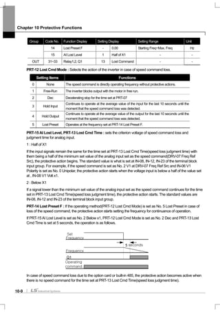
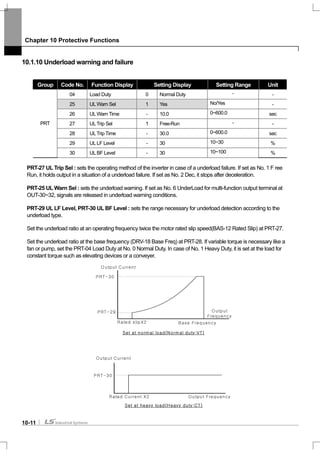
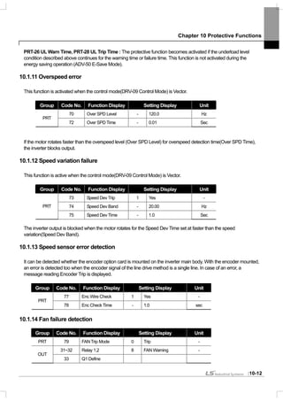
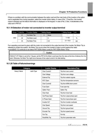
Download to read offline


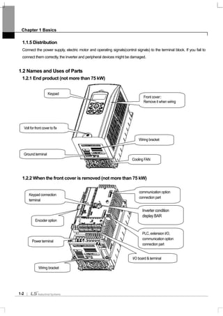
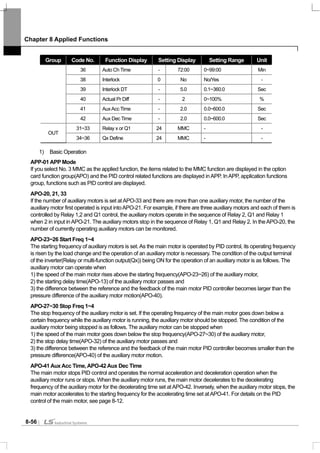
![Chapter 1 Basics
1-1
1.1 What You Should Know before Use
1.1.1 Check of product
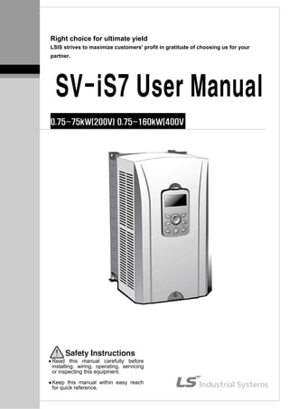
Take the inverter out of the box, check the rating shown on a side of the product body and whether the inverter type
and rated output are exactly what you ordered. Check also whether the product has been damaged during delivery.
SV 008 iS7 - 2 N O F D
Capacity ofApplied Motor
Series
Name
Input Voltage Keypad UL EMC DCR
0008 0.75 [kW]
0015 1.5 [kW]
0022 2.2 [kW]
0037 3.7 [kW]
0055 5.5 [kW]
0075 7.5 [kW]
0110 11 [kW]
0150 15 [kW]
0185 18.5 [kW]
0220 22 [kW]
0300 30 [kW]
0370 37 [kW]
0450 45 [kW]
0550 55 [kW]
0750 75 [kW]
0900 90 [kW]
1100 110 [kW]
1320 132 [kW]
LSInverter
1600 160 [kW]
Wide-UseInverter
-
2: 3-Phase
200~230[V]
4: 3-Phase
380~480[V]
N: NON
S: GLCD
(Graphic
Loader)
O:OPEN
E: Enclosed
ULType1
note1)
P: Enclosed
ULType 12
Blank:
Non-
EMC
F:EMC
Blank:
Non-
DCR
D:DCR
Note1)
Enclosed ULType 1 has the conduit option addtionally at 0.75 through 75 kW products.
1.1.2 Parts
If you have any doubt about the product or found the product damaged, call our company’s branch offices(see the
back cover of the manual).
1.1.3 Preparation of device and Parts for operation
Preparation for operation might slightly vary. Prepare parts according to the use.
1.1.4 Installation
Make sure you install the product correctly considering the place, direction or surroundings in order to prevent
decrease in the life and performance of the inverter.](https://image.slidesharecdn.com/is7eng101201-140613211330-phpapp02/85/I-s7-eng_101201-18-320.jpg)

![Chapter 2 Specifications
2-1
2.1 Specifications
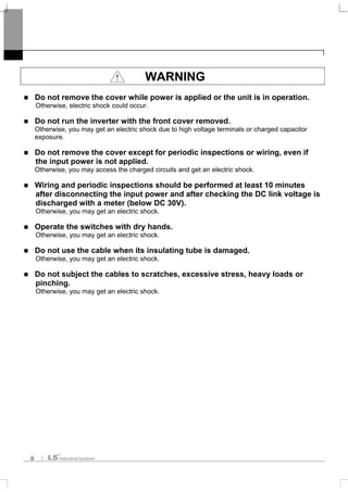
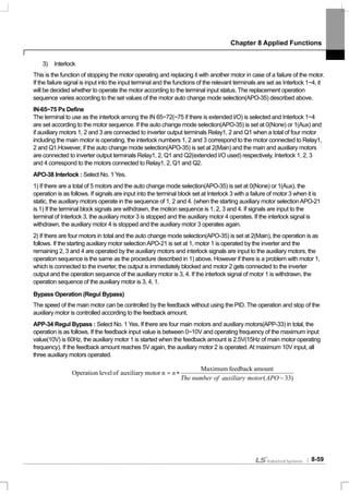
2.1.1 Rated Input and Output : Input voltage of 200V class (0.75~22kW)
Type : SV xxx iS7 – 2x 0008 0015 0022 0037 0055 0075 0110 0150 0185 0220
[HP] 1 2 3 5 7.5 10 15 20 25 301)
MotorApplied
[kW] 0.75 1.5 2.2 3.7 5.5 7.5 11 15 18.5 22
2)
Rated Capacity
[kVA]
1.9 3.0 4.5 6.1 9.1 12.2 17.5 22.9 28.2 33.5
CT 5 8 12 16 24 32 46 60 74 883)
Rated
Current[A] VT 8 12 16 24 32 46 60 74 88 124
Output
Frequency
4)
0 ~ 400 [Hz]
RatedOutput
Output Voltage
[V]
5)
3-phase 200 ~ 230V
(Sensorless-1:0.1~300Hz, Sensorless-2,Vector:0.1~120Hz)
Available Voltage
[V]
3-phase 200 ~ 230 VAC (-15%,+10%,)
Input Frequency 50 ~ 60 [Hz] (±5%)
CT 4.3 6.9 11.2 14.9 22.1 28.6 44.3 55.9 70.8 85.3
RatedInput
Rated
Current [A] VT 6.8 10.6 14.9 21.3 28.6 41.2 54.7 69.7 82.9 116.1
* Non DCR products are provided warranty service when used in CT (Heavy duty) load rating only
2.1.2 Rated Input and Output : Input voltage of 200V class (30~75kW)
Type : SV xxx iS7 – 2x 0300 0370 0450 0550 0750 - - - - -
[HP] 40 50 60 75 100 - - - - -1)
MotorApplied
[kW] 30 37 45 55 75 - - - - -
2)
Rated Capacity
[kVA]
46 57 69 84 116 - - - - -
CT 116 146 180 220 288 - - - - -3)
Rated
Current[A] VT 146 180 220 288 345 - - - - -
Output
Frequency
4)
0 ~ 400 [Hz]
(Sensorless-1:0.1~300Hz, Sensorless-2,Vector:0.1~120Hz)
RatedOutput
Output Voltage
[V]
5)
3-phase 200 ~ 230V
Available Voltage
[V]
3-phase 200 ~ 230 VAC (-15%~+10%)
Input Frequency 50 ~ 60 [Hz] (±5%)
CT 121 154 191 233 305 - - - - -
RatedInput
Rated
Current [A] VT 152 190 231 302 362 - - - - -
* Non DCR products are provided warranty service when used in CT (Heavy duty) load rating only.](https://image.slidesharecdn.com/is7eng101201-140613211330-phpapp02/85/I-s7-eng_101201-21-320.jpg)
![Chapter 2 Specifications
2-2
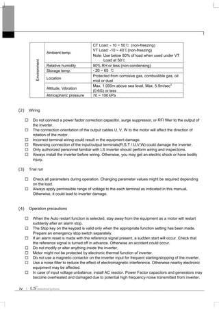
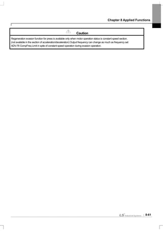
2.1.3 Rated Input and Output : Input voltage of 400V class (0.75~22kW)
Type : SV xxx iS7 – 4x 0008 0015 0022 0037 0055 0075 0110 0150 0185 0220
[HP] 1 2 3 5 7.5 10 15 20 25 301)
MotorApplied
[kW] 0.75 1.5 2.2 3.7 5.5 7.5 11 15 18.5 22
2)
Rated Capacity
[kVA]
1.9 3.0 4.5 6.1 9.1 12.2 18.3 22.9 29.7 34.3
CT 2.5 4 6 8 12 16 24 30 39 453)
Rated
Current[A] VT 4 6 8 12 16 24 30 39 45 61
Output Frequency
4)
0 ~ 400 [Hz]
(Sensorless-1: 0.1~300Hz, Sensorless-2, Vector: 0.1~120Hz)
RatedOutput
Output Voltage [V] 5)
3-phase 380 ~ 480V
Available Voltage
[V]
3-phase 380 ~ 480 VAC (-15%~+10%)
Input Frequency 50 ~ 60 [Hz] (±5%)
CT 2.2 3.6 5.5 7.5 11.0 14.4 22.0 26.6 35.6 41.6
RatedInput
Rated
Current [A] VT 3.7 5.7 7.7 11.1 14.7 21.9 26.4 35.5 41.1 55.7
* Non DCR products are provided warranty service when used in CT (Heavy duty) load rating only
2.1.4 Rated Input and Output : Input voltage of 400V class (30~160kW)
Type : SV xxx iS7 – 4x 0300 0370 0450 0550 0750 0900 1100 1320 1600 -
[HP] 40 50 60 75 100 120 150 180 225 -1)
MotorApplied
[kW] 30 37 45 55 75 90 110 132 160 -
2)
Rated Capacity
[kVA]
46 57 69 84 116 139 170 201 248 -
CT 61 75 91 110 152 183 223 264 325 -3)
Rated
Current[A] VT 75 91 110 152 183 223 264 325 370 -
Output Frequency
4)
0 ~ 400 [Hz]
(Sensorless-1: 0~300Hz, Sensorless-2, Vector: 0~120Hz)
RatedOutput
Output Voltage [V] 5)
3-phase 380 ~ 480V
Available Voltage
[V]
3-phase 380 ~ 480 VAC (-15%, +10%)
Input Frequency 50 ~ 60 [Hz] (±5%)
CT 55.5 67.9 82.4 102.6 143.4 174.7 213.5 255.6 316.3
RatedInput
Rated
Current[A] VT 67.5 81.7 101.8 143.6 173.4 212.9 254.2 315.3 359.3
* Non DCR products are provided warranty service when used in CT (Heavy duty) load rating only
1) MotorApplied indicates the maximum capacity applied to use of a standard 4 pole standard motor.
2) Rated capacity : the input capacity of a 200V class is based on 220V and that of a 400V class is based on 440V. The current
rating is based on CT current.
3) The output of rated current is limited according to setting of the carrier frequency (CON-04).
4) In case of Sensorless-1, you can set the frequency at up to 300Hz by selecting 3, 4 as the control mode (DRV-09 Control Mode).
In case of Sensorless-2, you can set the frequency at up to 120Hz by selecting 3, 4 as the control mode (DRV-09 Control Mode).
5) The maximum output voltage does not go up over the supplied power voltage. You can select the output voltage as you want
below the supplied power voltage.](https://image.slidesharecdn.com/is7eng101201-140613211330-phpapp02/85/I-s7-eng_101201-22-320.jpg)
![Chapter 2 Specifications
2-3
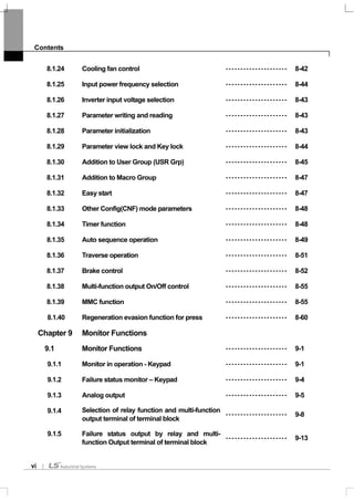
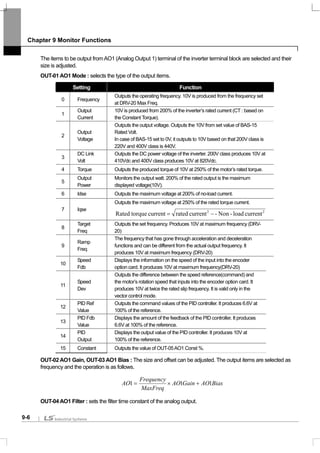
2.1.5 Other commons
1) Control
Control Method
V/F control, V/F PG, slip compensation, sensorless vector-1, sensorless vector-2,
vector control
Frequency Setting
Resolving Power
Digital command : 0.01Hz
Analog command : 0.06Hz (maximum frequency : 60Hz)
Frequency Degree
Digital command operation : 0.01% of the maximum frequency
Analog command operation : 0.1% of the maximum frequency
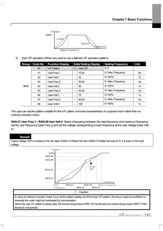
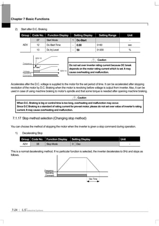
V/F Pattern Linear, double reduction, user V/F
Overload Capacity CT current rating :150% for 1 minute, VT current rating :110% for 1 minute
Torque Boost Manual torque boost,Automatic torque boost
* Non DCR products are provided warranty service when used in CT (Heavy duty) load rating only.
2) Operation
Operating Method Selectable among keypad/terminal block/communication operation
Frequency Setting
Analog: 0 ~ 10[V], -10 ~ 10[V], 0 ~ 20[mA]
Digital: keypad
Operating Function
PID control, up-down operation, 3-wire operation, DC break, Frequency limit,
Frequency jump, Second function, Slip compensation, Reverse rotation prevention,
Auto restarting, Inverter By-pass, Auto tuning Flying Start, Energy buffering, Power
breaking, Flux breaking, Leakage current reduction, MMC, Easy Start.
NPN (Sink) / PNP (Source) selectable
Input
Multi-function
terminal
(8 points)
P1 ~ P81)
Function: forward operation, reverse operation, reset, external trip, emergency stop,
jog operation, sequential frequency-high/medium/low, multi - level acceleration and
deceleration – high/medium/low, D.C. control during stop, selection of a second motor,
frequency increase, frequency decrease, 3-wire operation, change to general operation
during PID operation, Main inverter body operation during option operation, analog
command frequency fixation, acceleration and deceleration stop selectable.
Multi-function
open collector
terminal
Below DC 24V 50mA
Multi-function
relay terminal
Failure output and inverter operation
output
Below (N.O., N.C.)AC250V 1A,
Below DC 30V 1A
Output
Analog output
0 ~ 10 Vdc (below 20mA) : selectable from frequency, current, voltage, direct current
voltage
1) The Functions for Multi-function terminal available according to IN-65~72 parameter setting of IN Group.](https://image.slidesharecdn.com/is7eng101201-140613211330-phpapp02/85/I-s7-eng_101201-23-320.jpg)


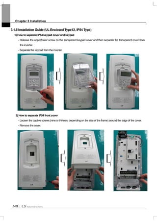
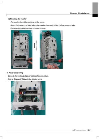
![Chapter 3 Installation
3-18
3.1.4 Dimension and Weight of frame (UL Enclosed Type 1, IP 21 Type)
Inverter Capacity W[mm] H[mm] D[mm]
EMC&DCL
Weight
[Kg]
Only EMC
Product
weight[Kg]
Only DCL
Product
weight[Kg]
Non EMC&DCL
Product
weight[Kg]
SV0008iS7-2/4 150 284 200 5.5 4.5 5.0 4.5
SV0015iS7-2/4 150 284 200 5.5 4.5 5.0 4.5
SV0022iS7-2/4 150 284 200 5.5 4.5 5.0 4.5
SV0037iS7-2/4 150 284 200 5.5 4.5 5.0 4.5
SV0055iS7-2/4 200 355 225 10 8.4 9.3 7.7
SV0075iS7-2/4 200 355 225 10 8.4 9.3 7.7
SV0110iS7-2/4 250 385 284 20 17.2 16.8 14
SV0150iS7-2/4 250 385 284 20 17.2 16.8 14
SV0185iS7-2 280 461.6 298 30 27 25.9 22.9
SV0220iS7-2 280 461.6 298 30 25.8 25.9 22.9
SV0300iS7-2 300 570 265.2 - - - 29.5
SV0370iS7-2 370 630 281.2 - - - 44
SV0450iS7-2 370 630 281.2 - - - 44
SV0550iS7-2 465 750 355.6 - - - 72.5
SV0750iS7-2 465 750 355.6 - - - 72.5
SV0185iS7-4 280 461.6 298 27.4 23.5 23.3 19.7
SV0220iS7-4 280 461.6 298 27.4 23.5 23.5 20.1
SV0300iS7-4 300.1 594.1 303.2 - - 41 28
SV0370iS7-4 300.1 594.1 303.2 - - 41 28
SV0450iS7-4 300.1 594.1 303.2 - - 41 28
SV0550iS7-4 370.1 663.5 373.3 - - 63 45
SV0750iS7-4 370.1 663.5 373.3 - - 63 45
SV0900iS7-4 510 783.5 422.6 - - 101 -
SV1100iS7-4 510 783.5 422.6 - - 101 -
SV1320iS7-4 510 861 422.6 - - 114 -
SV1600iS7-4 510 861 422.6 - - 114 -
Note
Weight[Kg] above indicates total weight including EMC FILTER, DCL. (excluding box packing)
30~160 kW products have only DCL option.](https://image.slidesharecdn.com/is7eng101201-140613211330-phpapp02/85/I-s7-eng_101201-42-320.jpg)
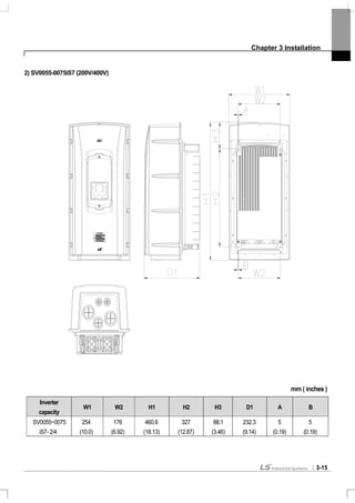
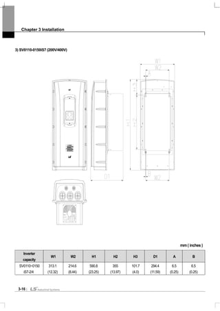
![Chapter 3 Installation
3-19
3.1.5 Dimension and Weight of Frame (UL Enclosed Type 12, IP54 Type)
Inverter Capacity W[mm] H[mm] D[mm]
EMC&DCL
Weight[Kg]
Only EMC
Weight[Kg]
Only DCL
Weight[Kg]
Non EMC&DCL
Weight[Kg]
SV0008iS7-2/4 204.2 419 208 8.2 7.2 7.7 6.7
SV0015iS7-2/4 204.2 419 208 8.2 7.2 7.7 6.7
SV0022iS7-2/4 204.2 419 208 8.2 7.2 7.7 6.7
SV0037iS7-2/4 204.2 419 208 8.2 7.2 7.7 6.7
SV0055iS7-2/4 254 460.6 232.3 12.8 10.2 12.1 9.5
SV0075iS7-2/4 254 460.6 232.3 12.9 10.3 12.2 9.6
SV0110iS7-2/4 313.1 590.8 294.4 25.6 22.8 22.4 19.6
SV0150iS7-2/4 313.1 590.8 294.4 25.9 23.1 22.7 19.9
SV0185iS7-2 343.2 750.8 315.5 38.3 34.2 34.1 29.9
SV0220iS7-2 343.2 750.8 315.5 38.3 34.2 34.1 29.9
SV0185iS7-4 343.2 750.8 315.5 34.9 31 31 27.1
SV0220iS7-4 343.2 750.8 315.5 34.9 31 31 27.1
Note
Weight[Kg] above indicates total weight. (excluding packing)
0.75~22 kW products have only IP54 type product.](https://image.slidesharecdn.com/is7eng101201-140613211330-phpapp02/85/I-s7-eng_101201-43-320.jpg)


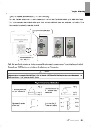
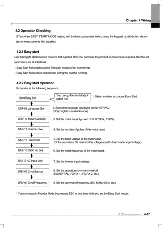
![Chapter 4 Wiring
4-2
3) How to separate front cover
[IP21 Type]
[IP54 Type]
Separate the transparent keypad cover releasing fixed bolt and then separate keypad.
Separate the front cover releasing fixed bolt.
Before wiring, IP54 product must be installed on the panel.
Separate front
cover
releasing the
fixed bolt.
I/O board control circuit
Terminal
Power circuit terminal
Front
cover
fixed
bolt
Keypad
Keypad fixed cover
Wiring hole
Built-in
circulation fan
Keypad
cover
fixed bolt](https://image.slidesharecdn.com/is7eng101201-140613211330-phpapp02/85/I-s7-eng_101201-48-320.jpg)


![Chapter 4 Wiring
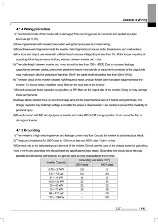
4-11
In case of lengthy wiring, Use thick wire in order to reduce line voltage drop and decrease the carrier frequency or use a
micro surge filter.
Line Voltage Drop[V]=(√3 X wire resistance [mΩ/m]X wire length[m] X Current[A])/1000
Distance between inverter and motor Up to 50 m Up to 100 m Over 100 m
Permitted carrier frequency Below 15 kHz Below 5 kHz Below 2.5 kHz
4.1.9 Control terminal line diagram (Basic I/O terminal block, below 22kW products)
1) How to set NPN (Sink)/PNP (Source)
iS7 serves 2 sequence input terminal of control circuit: NPN mode (Sink mode) and PNP mode(Source mode). It is
possible to change the logic of input terminal with NPN mode (Sink mode) and PNP mode (Source mode) by using
NPN (Sink)/PNP (Source) set terminal. Each mode connecting methods are follows.
(1) NPN mode(Sink mode)
Set NPN (Sink)/PNP (Source) switch into NPN. CM (24V GND) is common terminal of contact point input signal. Initial
set of Factory default is NPN mode (Sink mode).
I / PTC
set terminal
TR
NPN (Sink)
/PNP (Source)
set terminal
Inner source(24V)
CM(24G)
P1(FX)
P2(RX)
NPNPNP
NPN mode (Sink mode)](https://image.slidesharecdn.com/is7eng101201-140613211330-phpapp02/85/I-s7-eng_101201-57-320.jpg)


![Chapter 4 Wiring
4-15
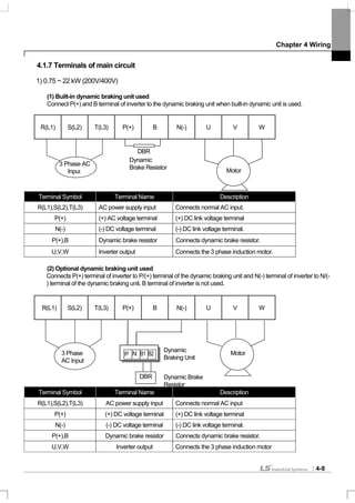
4.1.11 Control circuit terminal
1) Contact point start function selection
Type
Terminal
Symbol
Terminal Name Terminal Description
P1~P8
Multi-function
input1~8
Available by defining as multi-function input
Contact
point start
function
selection
CM
Sequence
common terminal
Common terminal of the contact point input terminal
(note: In case of Basic I/O, common terminal is different from the
5G common terminal)
VR(+)
Frequency setting
power(+) terminal
Power supply for analog frequency setting
Maximum output is +12V, 100mA.
VR(-)
Frequency setting
power(-) terminal
Power supply for analog frequency setting
Maximum output is -12V, 100mA.
V1
Frequency setting
(voltage)
Becomes set frequency with input of DC -10~10V.
Unipolar 0~+10[V]),Biopolar(-10[V] ~10[V]) input resistance 20kΩ
I1
Frequency setting
(current)
Becomes set frequency with input of DC 0~20mA
input resistance 249Ω
Inputsignal
Analog
Frequency
5G
Frequency setting
common terminal
Common terminal of analog frequency setting signal and analog
voltage and current terminals
(note: In case Basic I/O, common terminal are different from the
CM common terminal)
A01
Multi-function
analog voltage
output terminal
Select the one among Output frequency, Output current, and DC
voltage.
Ouput voltage: 0~10V
Maximum output voltage: 10V
Maximum output current: 10mA
Analog
A02
Multi-function
analog current
output terminal
Select the one among Output frequency, Output current, Output
voltage and DC voltage.
Output current: 4~20mA (0~20mA)
Maximum output current: 20mA
Q1
Multi-function
terminal
(open collector)
DC 26V, below 100mA
EG
Common terminal
for open collector
External power supply common earth terminal of the open
collector
24
Exterior 24V
power
Maximum output current: 150mA
A1,
B1,C1
Fault signal output
Protection function is activated to break output.
(below AC250V 1A, DV30V 1A)
Fault signal: A1-C1 electrified (B1-C1 unelectrified)
Normal signal: B1-C1 electrified (A1-C1 unelectrified)
A2, C2
Multi-functionrelay2
output A contact
point
Output the signal while running. User defined multi-function output
terminal.
AC250V, below 5A
DC30V, below 5A
OutputSignal
Contact
Point
S+,S-,CM
RS-485 signal
input terminal
RS-485 signal line
(see Chapter 11 Communication Function of the manual.)](https://image.slidesharecdn.com/is7eng101201-140613211330-phpapp02/85/I-s7-eng_101201-61-320.jpg)


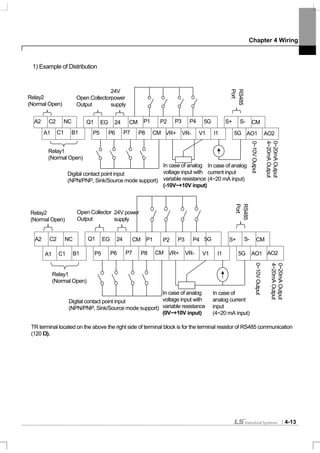
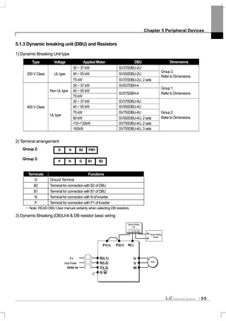
![Chapter 5 Peripheral Devices
5-2
5.1.2 Specifications of wiring switch, Electronic contactor and Reactor
1) Specifications of Wiring switch and Electronic contactor
Inverter
capacity
MCCB/
ELCB
(LS)
Rated
Current
[A]
Magnetic
Contactor
(LS)
Inverter
capacity
MCCB/
ELCB
(LS)
Rated
Current
[A]
Magnetic
Contactor
(LS)
0008iS7-2
ABS33b/
EBS33b
15 GMC-9 0008iS7-4
ABS33b/
EBS33b
15 GMC-9
0015iS7-2
ABS33b /
EBS33b
15 GMC-12 0015iS7-4
ABS33b/
EBS33b
15 GMC-9
0022iS7-2
ABS33b /
EBS33b
30 GMC-18 0022iS7-4
ABS33b/
EBS33b
15 GMC-12
0037iS7-2
ABS33b /
EBS33b
30 GMC-32 0037iS7-4
ABS33b/
EBS33b
15 GMC-18
0055iS7-2
ABS53b /
EBS53b
50 GMC-40 0055iS7-4
ABS33b/
EBS33b
30 GMC-22
0075iS7-2
ABS103b /
EBS63b
60 GMC-50 0075iS7-4
ABS33b/
EBS33b
30 GMC-32
0110iS7-2
ABS103b /
EBS103b
100 GMC-65 0110iS7-4
ABS53b/
EBS53b
50 GMC-40
0150iS7-2
ABS203b/
EBS203b
125 GMC-100 0150iS7-4
ABS103b /
EBS63b
60 GMC-50
0185iS7-2
ABS203b /
EBS203b
150 GMC-125 0185iS7-4
ABS103b /
EBS103b
80 GMC-65
0220iS7-2
ABS203b /
EBS203b
175 GMC-150 0220iS7-4
ABS103b /
EBS103b
100 GMC-65
0300iS7-2
ABS203b/
EBS203b
GMC-150 0300iS7-4
ABS203b /
EBS203b
125 GMC-100
0370iS7-2
ABS403b/
EBS403b
GMC-220 0370iS7-4
ABS203b /
EBS203b
150 GMC-125
0450iS7-2
ABS403b/
EBS403b
GMC-300 0450iS7-4
ABS203b/
EBS203b
175 GMC-150
0550iS7-2
ABS603b/
EBS603b
GMC-400 0550iS7-4
ABS203b/
EBS203b
225 GMC-180
0750iS7-2
ABS603b/
EBS603b
GMC-600 0750iS7-4
ABS403b /
EBS403b
300 GMC-220
0900iS7-4
ABS403b /
EBS403b
400 GMC-300
1100iS7-4
ABS603b /
EBS603b
500 GMC-400
1320iS7-4
ABS603b /
EBS603b
600 GMC-400
MCCB: Molded Case Circuit Breakers
ELCB: Earth Leakage Circuit Breakers
1600iS7-4
ABS603b /
EBS603b
600 GMC-600](https://image.slidesharecdn.com/is7eng101201-140613211330-phpapp02/85/I-s7-eng_101201-66-320.jpg)


![Chapter 5 Peripheral Devices
5-7
6) DB Resistors
(1) Option type Dynamic Breaking Unit
Following table has reference that DC breaking torque: 150%, %ED: 5%. Rating Watt of DBU has to be doubled
when %ED is 10%.
150% Breaking Torque, 5%ED
Voltage Class
Inverter
Capacity (kW)
Type
Resistor [ohm] Watt [W] Appearance
0.75 BR0400W150J 150 150 TYPE 1
1.5 BR0400W060J 60 300 TYPE 1
2.2 BR0400W050J 50 400 TYPE 1
3.7 BR0600W033J 33 600 TYPE 2
5.5 BR0800W020J 20 800 TYPE 3
7.5 BR1200W015J 15 1200 TYPE 3
11 BR2400W010J 10 2400 TYPE 3
15 BR2400W008J 8 2400 TYPE 3
18.5 BR3600W005J 5 3600 TYPE 3
22 BR3600W005J 5 3600 TYPE 3
30 - 5 5000 -
37 - 4.5 7000 -
45 - 3.5 10000 -
55 - 3.0 15000 -
200V Class
75 - 2.5 20000 -
0.75 BR0400W600J 600 150 TYPE 1
1.5 BR0400W300J 300 300 TYPE 1
2.2 BR0400W200J 200 400 TYPE 1
3.7 BR0600W130J 130 600 TYPE 2
5.5 BR1000W085J 85 1000 TYPE 3
7.5 BR1200W060J 60 1200 TYPE 3
11 BR2000W040J 40 2000 TYPE 3
15 BR2400W030J 30 2400 TYPE 3
18.5 BR3600W020J 20 3600 TYPE 3
22 BR3600W020J 20 3600 TYPE 3
30 - 12 5000 -
37 - 12 5000 -
45 - 6 10,000 -
55 - 6 10,000 -
75 - 6 10,000 -
90 - 4.5 15,000 -
110 - 3.5 17,000 -
132 - 3.0 20,000 -
400V Class
160 - 2.5 25,000 -
Caution
In case of iS7 90~160kW, Dynamic braking unit for 220kW (SV2200DB-4) needs above listed DB resistor. If Dynamic braking unit
(SV075DBH-4) is connected in parallel, use above listed DB resistor inparallel.](https://image.slidesharecdn.com/is7eng101201-140613211330-phpapp02/85/I-s7-eng_101201-71-320.jpg)


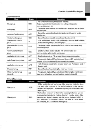


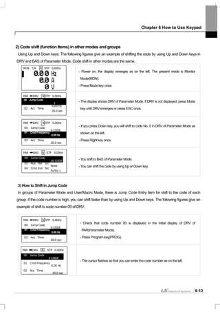
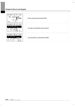
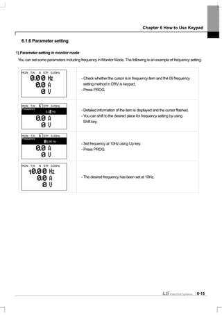

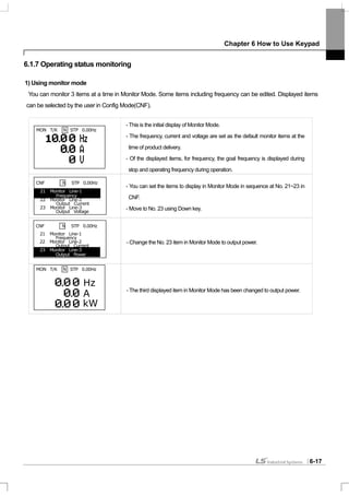
![Chapter 6 How to use Keypad
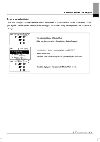
6-18
2) Possible to monitoring items
Mode Code
Function
Display
Setting Range Initial Value
20 Anytime Para 0 Frequency 0: Frequency
21 Monitor Line-1 1 Speed 0: Frequency
22 Monitor Line-2 2 Output Current 2:Output Current
3 Output Voltage
4 Output Power
5 WHour Counter
6 DCLink Voltage
7 DI Status
8 DO Status
9 V1 Monitor[V]
10 V1 Monitor[%]
11 I1 Monitor[mA]
12 I1 Monitor[%]
13 V2 Monitor[V]
14 V2 Monitor[%]
15 I2 Monitor[mA]
16 I2 Monitor[%]
17 PID Output
18 PID ref Value
19 PID Fdb Value
20 Torque
21 Torque Limit
22 Trq Bias Ref
23 Speed Limit
CNF
23 Monitor Line-3
24 Load Speed
3:Output Voltage](https://image.slidesharecdn.com/is7eng101201-140613211330-phpapp02/85/I-s7-eng_101201-89-320.jpg)


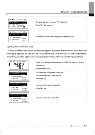
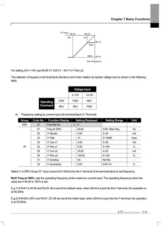
![Chapter 7 Basic Functions
7-3
IN-07 V1 Filter: used when the set frequency value fluctuates greatly due to the environment such as noise. If you set
the filter time constant high, you can reduce the frequency fluctuation but the response gets slower. The higher the time
constant is, the time (t) becomes longer. The set time refers to the time it takes the frequency set in the inverter to
increase by up to about 63% when the voltage input is input by step as follows.
IN-08 V1 Volt X1 ~ IN-11 V1 Perc y2: You can set the slope and offset value for the input voltage.
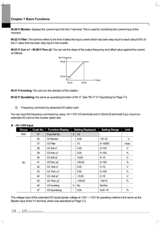
IN-16 V1 Inverting: If you set at No. 1 Yes, you can reverse the present revolution direction.
IN-17 V1 Quantizing: used when there is a lot of noise in the analog signals input into the terminal. You can also reduce
noise to some extent by using the IN-07 low pass filter value but the higher the value is, the responsiveness becomes
slower and pulsation of a long cycle might occur. The resolving power of output frequency for analog input decreases but
the noise effect is reduced by the quantizing function in a system sensitive to noise.
The set quantization value is the percentage of the maximum analog input value. Therefore if the maximum input value is
10V and the quantization value is set at 1%, the frequency changes by 0.06Hz (when the maximum frequency is 60Hz)
at an interval of 0.1V. The output frequency when the input value increases and decreases differs so that the effect of
analog input value fluctuation is removed.
If the quantization value is quadrisected and the analog input value increases, when a value three fourths the
quantization value is input, the output frequency changes and from the next step it increases along with the quantization
value as follows. If the analog input value decreases by 1/4 of the quantization value, the output frequency changes.
V1 input
Set
t
Output
Frequency[Hz]
Analog Input[V]
10
9.975
9.925
0.075
0.025 0.1 0.2
0.175
60.00
59.94
1.2
0.6
IN-08
IN-09
IN-11
Set Frequency
V1 Input
IN-10](https://image.slidesharecdn.com/is7eng101201-140613211330-phpapp02/85/I-s7-eng_101201-96-320.jpg)
![Chapter 7 Basic Functions
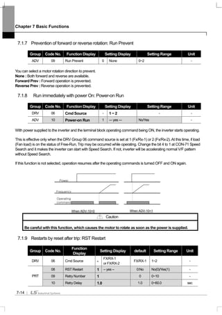
7-4
(3) If -10~+10V is input,
Group Code No. Function Display Setting Displayed Setting Range Unit
DRV 07 Freq Ref Src 2 V1 - -
01 Freq at 100% - 60.00 0.00~Max. Freq. Hz
05 V1 Monitor - 0.00 0~10V V
06 V1 Polarity 1 Bipolar Unipolar/ Bipolar -
12 V1 -volt x1’ - 0.00 0~10V V
13 V1 -Perc y1’ - 0.00 0~100% %
14 V1 -Volt x2’ - -10.00 0~10V V
IN
15 V1 -Perc y2’ - -100.00 0~100% %
Set IN-06 at Bipolar. Codes between 12 and 15 are displayed only when they are Bipolar and you can set the voltage
between 0 and -10V which is input into the V1 terminal.As follows, input into the V1 terminal in volume resistance by
using the voltage output of the external controller or the VR output terminal of the inverter control terminal block.
(in case of Basic I/O)
When -10~10V is used from the external circuit When connecting inner power source
*: In case, insulation I/O ground is CM terminal.
The output frequency of bipolar voltage input (-10~+10V) is as follows.
IN-12 V1 –volt x1’~ IN-15 V1 –Perc y2’: You can set the slope and offset value of the output frequency of (-) input voltage
as follows.
E.g.) If the minimum (-) input voltage if V1 is -2V, the output ratio of -2V is 10% and maximum voltage is -8V and then you
set the output ratio at 80%, the output frequency moves between 6Hz~48Hz..
V1
VR+
VR-5G*
V1
-10 ~ +10V
Forw ard O utput
F requency
R everse O utput
Frequency
Input
V oltage
0~10[V ]-10~0[V ]](https://image.slidesharecdn.com/is7eng101201-140613211330-phpapp02/85/I-s7-eng_101201-97-320.jpg)


![Chapter 7 Basic Functions
7-10
[Example of speed-8]
If multi-function terminals P5, P6, P7 and P8 are set at Speed-L, Speed-M, Speed-H and Speed-X respectively, you can
operate it as follows.
IN-89 In Check Time: If you use the multi-function terminal for sequential frequency setting, you can set the in check
time for the terminal block input within the inverter. For example, if you set the in check time at 100msec and input multi-
function terminal P6, it will be checked whether another terminal block input is input for 100msec.After 100msec, it is
accelerated or decelerated by the frequency corresponding to P6 terminal.
7.1.5 Operating command setting method
Group Code No. Function Display Initial Display
0 Keypad
1 Fx/Rx-1
2 Fx/Rx-2
3 Int 485
4 Field Bus
DRV 06 Cmd Source
5 PLC
Speed FX or RX P8 P7 P6
0 - - -
1 - -
2 - -
3 -
4 - -
5 -
6 -
7
Speed FX or RX P8 P7 P6 P5
0 - - - -
1 - - -
2 - - -
3 - -
4 - - -
5 - -
6 - -
7 -
8 - - -
9 - -
10 - -
11 -
12 - -
13 -
14 -
15
Frequency
P6
P7
8
FX
RX
0
1
3
4
5
6
7 8
2
P](https://image.slidesharecdn.com/is7eng101201-140613211330-phpapp02/85/I-s7-eng_101201-103-320.jpg)


![Chapter 7 Basic Functions
7-16
Caution
90 ~ 160 kW product’s acceleration initial value is 60.0sec and deceleration initial value is
90.0sec. Please do not confuse that displayed value at left bottom of keypad is D : 20.0, D : 30.0
it is applied for below 75kW product.
BAS-09 Time scale: Used when preciseAcc/Dec time is required due to the load characteristics or it is necessary to
increase the maximum set time. It changes the units of all the functions related to time.
Setting Range of Acc/Dec Time Precision
0 0.01 sec 0.00 ~ 60.00 Settable to 0.01 second
1 0.1 sec 0.0 ~ 600.0 Settable to 0.1 second
2 1 sec 0 ~ 6000 Settable to 1 second
Caution
Be careful because change of the unit leads to change of maximum settable time. If you change BAS-09
Time scale to 0(0.01sec) withAcc time set at 1000.0 seconds, theAcc time becomes 600.00 seconds.
2) Setting ofAcc/Dec Time Based on Operating Frequency
Group Code No. Function Display Setting Display Setting Range Unit
03 Acc Time - 20.0 0~600 sec
DRV
04 Dec Time - 30.0 0~600 sec
BAS 08 Ramp T Mode 1 Delta Freq Max Freq/Delta Freq -
If you set BAS-08 as Delta Freq, you can set theAcc/Dec time by the time it takes the current frequency during operation
at steady speed to reach the target frequency of the next step. If you set theAcc time at 5 seconds in case of step
operation between 10Hz and 30Hz while it is static, theAcc time is as follows.
Operating
Command
Operating
frequency
5 7 12
Time
[Sec]
5Sec 5 Sec
10Hz
30Hz](https://image.slidesharecdn.com/is7eng101201-140613211330-phpapp02/85/I-s7-eng_101201-109-320.jpg)

![Chapter 7 Basic Functions
7-18
You can change theAcc/Dec slope without using the multi-function terminal. The inverter operates at the slope set at
BAS-70, 71 below theAcc/Dec switching frequency set atADV-60 of the operating frequency. However, if the operating
frequency rises over theAcc/Dec switching frequency, the inverter runs at theAcc/Dec slope set at DRV-03 and 04.
If you set and input the function of the multi-function input terminal at sequentialAcc/Dec (Xcel-L, Xcel-M[HZ]), the
inverter runs byAcc/Dec input regardless of theAcc/Dec switching frequency.
7.1.11 Acc/Dec pattern setting
Group Code No. Function Display Initial Setting Display Setting Range Unit
BAS 08 Ramp T mode 0 Max Freq Max Freq/Delta Freq -
01 Acc Pattern 0 Linear 0~1 -
02 Dec Pattern 0 Linear 0~1 -
03 Acc S Start - 40 1~100 %
04 Acc S End - 40 1~100 %
05 Dec S Start - 40 1~100 %
ADV
06 Dec S End - 40 1~100 %
This sets the pattern of theAcc/Dec slope. There are 5 patterns, which have the following functions.
Type Function
0 Linear The output frequency is constant and increases or decreases linearly.
Used for applications requiring smoothAcc/Dec such as lift load and elevator door. The
curve rate of S-curve can be adjusted by using the functions of 03~06.
Caution
1 S-curve
Be careful when you set theAcc/Dec pattern at S-curve because it gets longer than the
setAcc/Dec time. For actualAcc/Dec time, see Page 7-19.
Operating
Command
Frequency
Acc Time Dec Time
Linear S-Curve
Frequency
FX
DRV-03
BAS-70 BAS-71
DRV-04
ADV-60](https://image.slidesharecdn.com/is7eng101201-140613211330-phpapp02/85/I-s7-eng_101201-111-320.jpg)
![Chapter 7 Basic Functions
7-19
ADV-03 Acc S Start: You can adjust the slope of the curve when you set theAcc/Dec pattern as S-curve. This is used to
adjust the curvilinear ratio of S-curve when acceleration begins. The curve ratio sets the ratio of the curve acceleration of
the 1/2 frequency on the basis of a half of the target frequency. For example, ifADV-03Acc S Start is set at 50% and the
target frequency, which equals the maximum frequency(max Freq[Hz]), is 60Hz, the frequency which the curve
acceleration accounts for when the S-curve accelerates to 30Hz is 0~15Hz and the 15Hz~30Hz interval is linear
acceleration.
ADV-04 Acc S End: You can adjust the slope of the curve when the operating frequency reaches the target frequency.
This is used to set the ratio accounted for by the curve acceleration of the remaining interval on the basis of the 1/2
frequency of the target frequency as in case ofAcc S Start. If set as inAcc S Start above, it accelerates in a linear slope
until 30~45Hz and then accelerates in a curve slope and operates at a steady speed for the remaining 45~60Hz interval.
ADV-05 Dec S Start ~ ADV-06 Dec S End: Sets the curve deceleration slope ratio during deceleration. The setting
method is as the acceleration ratio described above.
Acc/Dec Time in S-curve:
Acc Time = SetAcc Time + SetAcc Time x (ADV-03)/2 + SetAcc Time x (ADV-04)/2
Dec Time = Set Dec Time + Set Dec Time x (ADV-05)/2 + Set Dec Time x (ADV-06)/2
7.1.12 Acc/Dec Stop command
Group Code No. Function Display Setting Display Unit
IN 65~75 Px Define 25 XCELStop -
You can stop acceleration or deceleration using the multi-function terminal and operate at steady speed. The following
figure illustrates use of multi-function terminal P8.
Frequency
P8
Operating
Command
[ S-Curve Acc/Dec Pattern ]
Out Freq
(Hz)
S start
Time(sec)
Max Freq/2
Max Freq
S end
Linear
Variation of Delta
Frequency Time(sec)
S start S end
Linear](https://image.slidesharecdn.com/is7eng101201-140613211330-phpapp02/85/I-s7-eng_101201-112-320.jpg)

![Chapter 7 Basic Functions
7-22
7.1.14 Torque boost
1) Manual Torque Boost (When great start torque is necessary for elevator load, etc.)
Group Code No. Function Display Setting Display Setting range Unit
15 Torque Boost 0 Manual -
16 Fwd Boostnote1)
- 2.0 0~15 %DRV
17 Rev Boostnote1)
- 2.0 0~15 %
note1)
Default value of 90~160 kW is 1.0 [%].
This adjusts the output voltage of low speed operation or starting. It can improve the starting characteristic or raise the
low speed torque by increasing the output voltage in the low speed area.
DRV-16 Fwd Boost: adjusts the torque boost in forward rotation.
DRV-17 Rev Boost: adjusts the torque boost in reverse rotation.
Caution
Be careful not to set the torque boost too high because the motor might be overheated by over
excitation.
2) Automatic Torque Boost (Choosing automatic selection function for greater starting torque)
Group Code No. Function Display Setting Display Unit
DRV 15 Torque Boost 1 Auto -
BAS 20 Auto Tuning 2 Rs+Lsigma -
The inverter automatically calculates the torque boost and produces voltage by using the motor parameter.
Because the stator resistance of the motor, inductance value and no load current value are necessary for the automatic
torque boost to function, do auto tuning (BAS-20Auto Tuning) before use (Page 8-17).
FX
time
RX
Voltage
Forward Torque Boost
No Torque Boost
100 %
Reverse Torque Boost](https://image.slidesharecdn.com/is7eng101201-140613211330-phpapp02/85/I-s7-eng_101201-115-320.jpg)


![Chapter 8 Applied Functions
8-1
8.1 Applied Functions
8.1.1 Override frequency setting using auxiliary frequency command
(Setting frequency of various computation conditions using main and auxiliary speed such as Draw operation)
Group Code No. Function Display Setting Display Setting Range Unit
DRV 07 Freq Ref Src 0 Keypad-1 0~9 -
01 AUX Ref Src 1 V1 0~4 -
02 AUX Calc Type 0 M + G *A 0~7 -BAS
03 AUX Ref Gain - 0.0 200~200 %
IN 65~75 Px Define 40 DisAux Ref 0~48 -
You can set operating frequency by simultaneously using two methods of frequency setting. Main speed is used to set
the operating frequency, and the auxiliary speed can be used for precise adjustment during main speed frequency. For
example, let’s assume that the inverter has been set as in the table above. During operation at 30.00 Hz with Keypad-1
the main speed, if you supply voltage of -10~+10V to V1 terminal and set the gain at 5% (variables between IN-01 ~ IN-
16 are the initial values and IN-06 V1 Polarity is set as Bipolar), precise adjustment is possible up to 33.00~27.00 Hz.
BAS-01 AUX Ref Src : selects the type of input to be used as auxiliary speed.
Setting Type Function
0 None No auxiliary speed motion
1 V1 Selects the voltage input terminal of the control terminal block as the auxiliary speed.
2 I1 Selects the current input as the auxiliary speed.
3 V2 Selects the voltage input of the extended IO option board as the auxiliary speed.
4 I2 Selects the current input of the extended IO option board as the auxiliary speed.
BAS-02 Aux Calc Type : The reflection ratio of the main speed can be set by four operations after setting the amount of
the auxiliary speed as gain (BAS-03Aux Ref Gain).
Setting Type Expression Final Command Frequency Computation
0 M + (G *A) M[Hz] + (G[%] *A[Hz]) mainspeedcommandvalue+(BAS03xBAS01xIN01)
1 M * (G *A) M[Hz] * (G[%] *A[%]) mainspeedcommandvaluex(BAS03xBAS01)
2 M / (G *A) M[Hz] / (G[%] *A[%]) mainspeedcommandvalue/(BAS03xBAS01)
3 M+ (M * (G *A)) M[Hz] + (M[Hz] * (G[%] *A[%]))
mainspeedcommandvalue+(mainspeedcommandvaluex
(BAS03xBAS01))
4 M+ G * 2 * (A-50) M[Hz] + G[%] * 2 * (A[%] - 50[%])[Hz] mainspeedcommandvalue+BAS03x2x(BAS01–50)xIN01
5 M* ( G * 2 * (A-50)) M[HZ] * (G[%] * 2 * (A[%] - 50[%])) mainspeedcommandvaluex(BAS03x2x(BAS01–50))
6 M / (G * 2 * (A-50)) M[HZ] / (G[%] * 2 * (A[%] - 50[%])) mainspeedcommandvalue/(BAS03x2x(BAS01–50))
7
M+ M * G * 2 * (A-
50)
M[HZ] + M[HZ] * G[%] * 2 * (A[%]-
50[%])
mainspeedcommandvalue+mainspeedcommandvaluexBAS03x2x
(BAS01–50)](https://image.slidesharecdn.com/is7eng101201-140613211330-phpapp02/85/I-s7-eng_101201-123-320.jpg)
![Chapter 8 Applied Functions
8-2
M : main speed frequency command[Hz or RPM] by DRV-07 setting,
G : auxiliary speed[Hz or RPM] or gain[%],
A : auxiliary speed frequency command[Hz or RPM] or gain[%]
Of the setting types, numbers higher than No.4 can do (+) or (-) motions through only analog input.
BAS-03 Aux Ref Gain : adjusts the amount of the input(BAS-01Aux Ref Src) set as auxiliary speed.
If the auxiliary speed is set as V1 or I1 and the parameter of the terminal input group(IN) No. 01 ~ 32 is the initial value,
the auxiliary speed frequency operates as follows.
IN-65~75 Px Define : If the terminal set as No. 40 disAux Ref among the multi-function input terminals, the auxiliary
speed command is not active but only the main speed command is effective.
Example 1) If the frequency keypad is set in main speed and V1 analog voltage is in auxiliary speed,
Conditions:
- main speed (M) setting (DRV-07): Keypad (frequency is set at 30Hz)
- maximum frequency (Max Freq) setting (DRV-20): 400Hz
- auxiliary speed (A) setting (A:BAS-01): V1
(expresses auxiliary speed[Hz] or percentage[%] according to the computation setting condition)
- auxiliary speed gain (G) setting (BAS-03): 50% ,IN01~32: default value
Caution
If the maximum frequency is high, there might be an error of output frequency due to analog input and
computation error.
F (M,A,G)
Auxiliary speed command is OFF when the multi-function input
terminal is set as disAux Ref (IN65~75).
(frequency command by BAS-01 setting) Final command frequency
(frequency command by DRV-07 setting method)
Main Speed M
Auxiliary SpeedA](https://image.slidesharecdn.com/is7eng101201-140613211330-phpapp02/85/I-s7-eng_101201-124-320.jpg)
![Chapter 8 Applied Functions
8-3
If 6V is being input into V1, the frequency corresponding to 10V is 60Hz, so the auxiliary speedAin the table below is
36Hz (= 60[Hz] x (6[V] / 10[V])) or 60%(=100[%] X (6[V] / 10[V]) according to the condition.
Setting Type Final Command Frequency
0 M[Hz] + (G[%] *A[Hz]) 30Hz(M) + (50%(G) x 36Hz(A)) = 48Hz
1 M[Hz] * (G[%] *A[%]) 30Hz(M) x (50%(G) x 60%(A)) = 9Hz
2 M[Hz] / (G[%] *A[%]) 30Hz(M) / (50%(G) x 60%(A)) = 100Hz
3 M[Hz] + (M[Hz] * (G[%] *A[%])) 30Hz(M) + (30[Hz] x (50%(G) x 60%(A))) = 39Hz
4 M[Hz] + G[%] * 2 * (A[%] - 50[%])[Hz] 30Hz(M) + 50%(G) x 2 x (60%(A) – 50%) x 60Hz = 36Hz
5 M[HZ] * (G[%] * 2 * (A[%] - 50[%])) 30Hz(M) x (50%(G) x 2 x (60%(A) – 50%)) = 3Hz
6 M[HZ] / (G[%] * 2 * (A[%] - 50[%])) 30Hz(M) / (50%(G) x 2 x (60% – 50%)) = 300Hz
7 M[HZ] + M[HZ] * G[%] * 2 * (A[%] - 50[%]) 30Hz(M) + 30Hz(M) x 50%(G) x 2 x(60%(A) – 50%) = 33Hz
*If the set frequency is converted into rpm, Hz above changes into rpm.
Example 2) main speed (M) setting (DRV-07): Keypad (when the frequency command is set at 30Hz)
- maximum frequency (Max Freq)setting (DRV-20): 400Hz
- auxiliary speed (A)setting (BAS-01): I1
(expresses in auxiliary speed[Hz] or percentage[%] according to the condition)
- auxiliary speed gain (G)setting(BAS-03): 50%, IN01~32: default value
If 10.4mAis being input into I1, the frequency corresponding to 20mAis 60Hz, so the auxiliary speedAin the table below
is 24Hz (= 60[Hz] x ((10.4[mA] - 4[mA]) / (20[mA] - 4[mA])) or 40% (=100[%] x ((10.4[mA] - 4[mA]) / (20 [mA] - 4[mA])).
Setting Type Final Command Frequency
0 M[Hz] + (G[%] *A[Hz]) 30Hz(M) + (50%(G) x 24Hz(A)) = 42Hz
1 M[Hz] * (G[%] *A[%]) 30Hz(M) x (50%(G) x 40%(A)) = 6Hz
2 M[Hz] / (G[%] *A[%]) 30Hz(M) / (50%(G) x 40%(A)) = 150Hz
3 M[Hz] + (M[Hz] * (G[%] *A[%])) 30Hz(M) + (30[Hz] x (50%(G) x 40%(A))) = 36Hz
4 M[Hz] + G[%] * 2 * (A[%] - 50[%])[Hz] 30Hz(M) + 50%(G) x 2 x (40%(A) – 50%) x 60Hz = 24Hz
5 M[HZ] * (G[%] * 2 * (A[%] - 50[%])) 30Hz(M) x (50%(G) x 2 x (40%(A) – 50%)) = -3Hz (reverse)
6 M[HZ] / (G[%] * 2 * (A[%] - 50[%])) 30Hz(M) / (50%(G) x 2 x (60%–40%)) = -300Hz (reverse)
7 M[HZ] + M[HZ] * G[%] * 2 * (A[%] - 50[%]) 30Hz(M) + 30Hz(M) x 50%(G) x 2 x (40%(A) – 50%) = 27Hz
Example 3) main speed setting (DRV-07): V1 (if the frequency command is set at 5V and 30Hz)
- Max Freq [HZ] (DRV-20): 400Hz
- auxiliary speed (BAS-01): I1 (expresses in auxiliary speed[Hz] or percentage[%] according to the condition)
- auxiliary speed gain (BAS-03): 50% (represents G in the table below. The value is 0.5)
- IN01~32: default value](https://image.slidesharecdn.com/is7eng101201-140613211330-phpapp02/85/I-s7-eng_101201-125-320.jpg)
![Chapter 8 Applied Functions
8-4
If 10.4mAis being input into I1, the frequency corresponding to 20mAis 60Hz, so the auxiliary speedAin the table below
is 24Hz ( = 60[Hz] x ((10.4[mA] - 4[mA]) / (20[mA] - 4[mA])) or 40%( = 100[%] x ((10.4[mA] - 4[mA]) / (20 [mA] - 4[mA])).
Setting Type Final Command Frequency
0 M[Hz] + (G[%]*A[Hz]) 30Hz(M) + (50%(G) x 24Hz(A)) = 42Hz
1 M[Hz] * (G[%] *A[%]) 30Hz(M) x (50%(G) x 40%(A)) = 6Hz
2 M[Hz] / (G[%] *A[%]) 30Hz(M) / (50%(G) x 40%(A)) = 150Hz
3 M[Hz] + (M[Hz] * (G[%] *A[%])) 30Hz(M) + (30[Hz] x (50%(G) x 40%(A))) = 36Hz
4 M[Hz] + G[%] * 2 * (A[%] - 50[%]) [Hz] 30Hz(M) + 50%(G) x 2 x (40%(A) – 50%) x 60Hz = 24Hz
5 M[HZ] * (G[%] * 2 * (A[%] – 50[%])) 30Hz(M) x (50%(G) x 2 x (40%(A) – 50%)) = - 3Hz (reverse)
6 M[HZ] / (G[%] * 2 * (A[%] - 50[%])) 30Hz(M) / (50%(G) x 2 x (60% – 40%)) = - 300Hz (reverse)
7 M[HZ] + M[HZ] * G[%] * 2 * (A[%] - 50[%]) 30Hz(M) + 30Hz(M) x 50%(G) x 2 x (40%(A) – 50%) = 27Hz
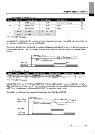
8.1.2 Jog operation (If you want Jog operation)
Operation is also available using the terminal block and the multi keys of the keypad.
1) Jog Operation by Terminal Block 1
*Px : P1~P8, P9~P11 (Option)
Select the jog frequency setting terminal from the multi-function terminals P1 ~ P11 and set the function of the appropriate
terminal block of IN-65 ~ IN-75 at No. 6 JOG. If the jog terminal which has been set with the operating command input,
the operating frequency moves to the jog frequency, which is described below.
DRV-11 Jog Frequency (Jog Frequency) : sets the frequency necessary for jog operation. Jog operation is the highest
in the priority order except the dwell operation. Therefore, during sequential operation, up-down operation and 3-wire
operation at a certain speed, if the jog terminal is input, it operates at the jog frequency.
DRV-12 JOG Acc Time, DRV-13 JOG Dec Time : the deceleration and acceleration time during shift to jog frequency.
Group Code No. Function Display Setting Display Setting Range Unit
11 JOG Frequency - 10.00 0.5~maximum frequency -
12 JOGAcc Time - 20.00 0~600 SecDRV
13 JOG Dec Time - 30.00 0~600 Sec
IN 65~75 Px Define 6 JOG - -
P1
P5
CM
FX
JOG](https://image.slidesharecdn.com/is7eng101201-140613211330-phpapp02/85/I-s7-eng_101201-126-320.jpg)


![Chapter 8 Applied Functions
8-15
2) PID Control Block Diagram
Notice
- If PID change operation (changes from PID operation to normal operation) comes into multi-function inputs
(P1~P11), the value of [%] is converted to the one of [Hz] and is output.
- Polarity of normal PID output PID OUT is unipolar and is limited by APP-29 (PID Limit Hi) and APP-30 (PID
Limit Lo).
- 100.0% is the standard of DRV-20 (maxFreq).
3) Pre-PID Operation
This is the function of normal acceleration to the set frequency without PID motion if an operating command is input and
starting PID operation when the control amount increases to a certain degree.
APP-34 Pre-PID Freq : The frequency to normal acceleration is input if normal acceleration is necessary without PID
control motion. For example, if Pre-PID Freq is set at 30Hz, normal operation continues at 30Hz until the control
amount(PID feedback amount) goes up above what is set inAPP-35.
APP-35 Pre-PID Exit, APP-36 Pre-PID Delay : PID control operation starts if the input feedback amount(control amount)
of the PID controller is larger than the value set inAPP-35. However, if an amount smaller than the value set inAPP-35
continues for the period of time set inAPP-36, the output is discontinued with a “Pre-PID Fail” trip.
PID
Limit Lo
PID Out
Inv
PID Ref Value
IN-
PID FBK
Value
Kf
PID Forward Gain
Keypad
P
D
I
0
Multi-function Input
Terminal Setting
MON Group
/
P Controller
Output Gain
P2
Main Speed
PID Ref Set
65~ 75
APP -22
APP - 45
APP - 24
Multi-function Input
Terminal Setting
(P 1~ P11) : P 2 Gain
IN - 65 ~75
MONGroup /
APP- 17
APP - 23APP -21
APP - 19
APP - 20
APP - 18
Multi-function Input
Terminal Setting
APP -29
APP -30
APP -31APP - 32
APP-26
APP -25
IN - 65 ~ 75
Target
Frequency
LimitGain
Encoder
Synchro
PLC
Binary
Fieldbus
V1
I 1
V2
I 2
Int . 485
Keypad - 1
Keypad - 2
Encoder
Synchro
PLC
Binary
Fieldbus
V1
V2
I 1
I 2
Int . 485
DRV - 07
( P 1~ P11)
: I Term Clear
PID Out
Inverse
PID Out
Scale
MON Group
APP -01 : Proc PID or MMC
PID F /B Selection
(P 1~P 11)
: PID Openloop
V1
I1
V2
Encoder
I2
Int . 485
Synchro
PLC
Binary
Fieldbus
PID Limit
Hi](https://image.slidesharecdn.com/is7eng101201-140613211330-phpapp02/85/I-s7-eng_101201-137-320.jpg)

![Chapter 8 Applied Functions
8-17
8.1.9 Auto tuning
The motor parameter can be automatically measured. In addition, if the encoder option card is connected to the main
body of the inverter, you can test the operation of the encoder. The motor parameters measured through auto tuning are
used for auto torque boost, sensorless vector control and vector control and so on.
Ex) 0.75kW, 220V class Motor
Group Code No. Function Display Setting Display Unit
DRV 14 Motor Capacity 2 0.75 kW
11 Pole Number - 4 -
12 Rated Slip - 40 rpm
13 Rated Curr - 3.6 A
14 Noload curr - 1.6 A
15 Rated Volt - 220 V
16 Efficiency - 72 %
20 Auto Tuning 0 None -
21 Rs - 26.00 Ω
22 Lsigma - 179.4 mH
23 Ls - 1544 mH
BAS
24 Tr - 145 msec
APO 04 Enc Opt Mode 0 None -
Input
voltage
Motor
capacity
[kW]
Rating
current
[A]
No load
current
[A]
Rating slip
frequency
[Hz]
Stator
resistance
[Ω]
Leakage
inductance
[mH]
0.2 1.1 0.8 3.33 14.0 40.4
0.4 2.4 1.4 3.33 6.70 26.9
0.75 3.4 1.7 3.00 2.600 17.94
1.5 6.4 2.6 2.67 1.170 9.29
2.2 8.6 3.3 2.33 0.840 6.63
3.7 13.8 5.0 2.33 0.500 4.48
5.5 21.0 7.1 1.50 0.314 3.19
7.5 28.2 9.3 1.33 0.169 2.844
11 40.0 12.4 1.00 0.120 1.488
200
15 53.6 15.5 1.00 0.084 1.118
Caution
Be sure to conduct auto tuning after the motor stops operating.
Before conducting auto tuning, make sure that you input the number of motor poles, rated slip, rated
current, rated voltage and efficiency shown on the motor plate. For the items not input, automatically
set values are used.](https://image.slidesharecdn.com/is7eng101201-140613211330-phpapp02/85/I-s7-eng_101201-139-320.jpg)
![Chapter 8 Applied Functions
8-18
Input
voltage
Motor
capacity
[kW]
Rating
current
[A]
No load
current
[A]
Rating slip
frequency
[Hz]
Stator
resistance
[Ω]
Leakage
inductance
[mH]
18.5 65.6 19.0 1.00 0.068 0.819
22 76.8 21.5 1.00 0.056 0.948
30 104.6 29.3 1.00 0.042 0.711
37 128.6 34.7 1.00 0.033 0.568
45 156.0 42.1 1.00 0.028 0.474
55 184.1 49.7 1.00 0.023 0.389
75 244.5 61.1 1.00 0.016 0.284
90 289.5 72.3 1.00 0.014 0.250
0.2 0.7 0.5 3.33 28.00 121.2
0.4 1.4 0.8 3.33 14.0 80.8
0.75 2.0 1.0 3.00 7.81 53.9
1.5 3.7 1.5 2.67 3.52 27.9
2.2 5.0 1.9 2.33 2.520 19.95
3.7 8.0 2.9 2.33 1.500 13.45
5.5 12.1 4.1 1.50 0.940 9.62
7.5 16.3 5.4 1.33 0.520 8.53
11 23.2 7.2 1.00 0.360 4.48
15 31.0 9.0 1.00 0.250 3.38
18.5 38.0 11.0 1.00 0.168 2.457
22 44.5 12.5 1.00 0.168 2.844
30 60.5 16.9 1.00 0.126 2.133
37 74.4 20.1 1.00 0.101 1.704
45 90.3 24.4 1.00 0.084 1.422
55 106.6 28.8 1.00 0.069 1.167
75 141.6 35.4 1.00 0.050 0.852
90 167.6 41.9 1.00 0.039 0.715
110 203.5 48.8 1.00 0.032 0.585
132 242.3 58.1 1.00 0.027 0.488
160 290.5 69.7 1.00 0.022 0.403
400
185 335.0 77.0 1.00 0.021 0.380
6) Motor Parameter Tuning (Rs, Lsigma, Ls, Tr, Noload curr)
BAS-20 Auto Tuning : Selects the type of auto tuning and implements auto tuning.Auto tuning starts if you select one of
the items below and press PROG.
0 : None
Displays the initial auto tuning item.After auto tuning is completed, that it is finished is displayed.](https://image.slidesharecdn.com/is7eng101201-140613211330-phpapp02/85/I-s7-eng_101201-140-320.jpg)


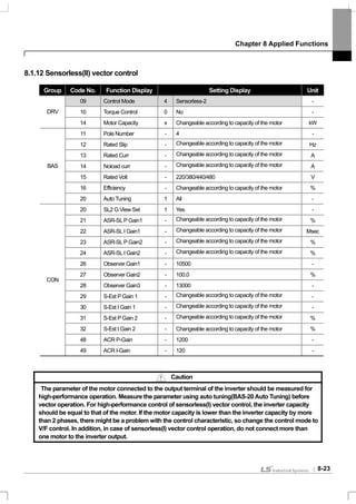

![Chapter 8 Applied Functions
8-25
2) Magnetic Flux Observer Controller Gain
CON-26 Observer Gain1, CON-27 Observer Gain2, CON-28 Observer Gain3 : For sensorless(II) vector control, the
observer for estimating the stator current and rotor magnetic flux of the motor is essential. Observer Gain1(CON-26)
applies at low and medium speed and Observer Gain2(CON-27) applies at medium and high speed and Observer
Gain3(CON-28) applies in the torque mode. It is recommended that you do not change the observer gain from its default
value.
Observer Gain2(CON-27) and Observer Gain3(CON-28) can be see only when SL2 G View Sel(CON-20) is set at No. 1
Yes.
3) Speed Estimator Gain
CON-29 S-Est P Gain1, CON-30 S-Est I Gain1 : The speed estimator gain of sensorless(II) vector control can be
changed. The speed estimator P gain or I gain can be increased or decreased by a small amount for adjustment when
the displayed value of speed is not equal to the goal value in a normal state. These gains can be also adjusted when
there is great vibration in the motor or high current ripple with power ON. In such a case, you can conduct a test mostly
by decreasing the P gain or I gain of the speed estimator. The speed estimator gain is set according to the default motor
parameter andAcc/Dec time.
CON-31 S-Est P Gain2, CON-32 S-Est I Gain1 : Can be see only when SL2 G View Sel(CON-20) is set at No. 1 Yes.
The speed estimator gain can be changed at higher than the medium speed(above a half of the base frequency) in
sensorless(II) vector control.
CON-31 S-Est P Gain2 and CON-32 S-Est I Gain1 are respectively set as the percentage of low speed gain CON-29 S-
Est P Gain1 and CON-30 S-Est I Gain1. For example, if CON-29 S-Est P Gain1 is 300 and CON-31 S-Est P Gain2 is
40.0%, the speed estimator P gain at higher than the actual medium speed is 120. The setting method is the same as
the low and medium speed gain setting method. The speed estimator gain is set according to the default motor
parameter andAcc/Dec time.
CON-34 SL2 OVM Perc : Output Voltage have a linearity for Input Voltage at non-overmodulation area which the ratio of
Output Voltage /Input Voltage is below 100%.At CON-34 (SL2 OVM Perc) can set the voltage range which is limited at
Sensorless-2 overmodulation area. In a application such as impact load (Press etc.; Torque limit<load), Tripless
operation can be possible by increasing the value of CON34 (SL2 OVM Perc) when load is applied. (Default value: 120
[%])
Also, Input Voltage is lower than nominal voltage at the area where supply a unstable input voltage so OC1 Trip is
occurred frequently when heavy reverse load such as impact load (Torque Limit<Load) is applied. The Trip caused by
lower Output Voltage. In this case, set the CON-34 (SL2 OVM Perc) to 140~150% and you can operate Tripless
operation in case heavy load is applied.
CON-48 ACR P-Gain, CON-49 ACR I Gain :Adjusts the P gain and I gain of the current PI controller.
DRV-10 Torque Control : The speed control mode and torque control mode are selected from the sensorless(II) vector
control mode and used. If the torque control(DRV-10) is set as Yes, operation is carried out in the torque control mode.
For details on the torque control mode, see 8.1.14 Torque control.
Caution
The controller gain can be adjusted according to the load characteristic. However, motor overheat of
system instability might occur according to the controller gain setting.](https://image.slidesharecdn.com/is7eng101201-140613211330-phpapp02/85/I-s7-eng_101201-147-320.jpg)


![Chapter 8 Applied Functions
8-53
[When the control mode is not vector ]
1) Brake Open Sequence
If an operating command is given with the motor static, the inverter accelerates to the open frequency(ADV-
44,45) forward or reversely. When the current through the motor reaches the brake open current(BR Rls Curr)
after reaching the brake open frequency, the brake open signals are released with the output relay or multi-
function output terminal set for brake control.Acceleration starts after the frequency is maintained for the brake
open delay time(BR Rls Dly).
2) Brake Closed Sequence
If a stop command is given during operation, the motor decelerates. When the output frequency reached the
brake closed frequency(BR Eng Fr), deceleration stops and the brake closed signal is released to the set output
terminal.After being maintained for the brake closed delay time(BR Eng Dly), the output frequency becomes 0. If
the DC braking time(ADV-15) or DC braking amount(ADV-16) is set, inverter output is blocked after DC braking.
For DC braking motion, see page 7-27.
ADV-41
ADV-42
ADV-46
ADV-15
ADV-47
Motor speed
Brake closed
interval
When Control Mode Is Not Set at Vector
ADV-44, 45
Brake closed
interval
Output
frequency
Output
currency
Brake Output
terminal
Operation
command
Brake open
interval](https://image.slidesharecdn.com/is7eng101201-140613211330-phpapp02/85/I-s7-eng_101201-175-320.jpg)
![Chapter 8 Applied Functions
8-54
[When the control mode is set at vector]
1) Brake Open Sequence
If the operating command is input, the brake open signal is released with the output terminal set after the initial
excitation time.Acceleration starts after the brake open delay time(BR Rly Dly).
2) Brake Closed Sequence
If a stop command is given, deceleration is carried out until the speed reaches 0 and the brake closed signal is
released. Output is blocked after the set brake closed delay time(BR Eng Dly). This is not active in the torque
control mode.](https://image.slidesharecdn.com/is7eng101201-140613211330-phpapp02/85/I-s7-eng_101201-176-320.jpg)


![Chapter 8 Applied Functions
8-60
8.1.40 Regeneration evasion function for press
(To evade control operation in the status of regeneration during press)
This function is the one to prevent regeneration region, raising the speed of motor operation speed during press in the
status of motor regeneration.
Group Code No. Function Display Setting Display and Range Initial Value Unit
0 No
74 RegenAvd Sel
1 Yes
0: No -
200V class: 300~400V 350V
75 RegenAvd Level
400V class: 600~800V 700V
V
76 CompFreq Limit 0~ 10.00Hz 1.00[Hz] Hz
77 RegenAvd Pgain 0 ~ 100.0% 50.0[%] %
ADV
78 RegenAvd Igain 20~30,000msec 500[msec] msec
ADV-74 RegenAvd Sel (select regeneration evasion function for press):
During constant speed operation of the motor, select when frequent regeneration voltage occurs, damage and short life
of DB Unit due to excessive DB Unit operation or DB Unit operation is evaded limiting DC Link voltage.
ADV-75 RegenAvd Level (set regeneration evasion level for press):
Set DB operation evasion voltage when DC Link voltage goes up by regeneration voltage.
ADV-76 CompFreq Limit (limit regeneration evasion compensation frequency for press):
Set changeable frequency range for real command frequency during regeneration operation region.
ADV-77 RegenAvd P gain (P gain set for regeneration evasion compensation control machine function for press)
ADV-78 RegenAvd I gain (I gain set for regeneration evasion compensation control machine function for press):
Set P, I Gain of DC Link voltage limit PI control machine for regeneration operation region.
DC voltage(Vdc)
Output
Frequency (Hz)
ADV-76 compensation frequency limit range
Command
frequency
ADV-75 regeneration evasion level voltage
Status during regeneration evasion](https://image.slidesharecdn.com/is7eng101201-140613211330-phpapp02/85/I-s7-eng_101201-182-320.jpg)
![Chapter 9 Monitor Functions
9-1
9.1 Monitor Functions
9.1.1 Monitor in operation - Keypad
You can monitor the operating status using the keypad of the inverter. You can select the desired items to monitor
in the config mode(CNF), watch three items at a time in the monitor mode and select an item in the status display.
1) Selection of Monitor Mode Display
Mode Group Code No.
Function
Display
Initial Setting Unit
- 21 Monitor Line-1 0 Frequency Hz
- 22 Monitor Line-2 2 Output Current A
- 23 Monitor Line-3 3 Output Voltage V
CNF
24 Mon Mode Init 0 No -
CNF-21~23 Monitor Line-x : Selects the items to display in the monitor mode. Monitor mode is displayed first
when the power is supplied and all three items of Monitor Line-1 ~ Monitor Line-3 can be displayed
simultaneously. Choose from the following items suited to the line you want to display. If you choose Yes in CNF-
24 Mon Mode Init, CNF-21~23 is initialized.
Setting Function
0 Frequency
During stop, the set frequency is displayed during operation, the
currently output operating frequency is displayed in Hz unit.
1 Speed The same as above(0) and displayed in rpm unit.
2 Output Current Displays the magnitude of the output current.
3 Output Voltage Displays the output voltage.
4 Output Power Displays the output power.
5 WHour Counter Displays the electricity consumed by the inverter.
6 DCLink Voltage
Displays the DC power voltage inside the inverter. During stop,
it represents the maximum value of the DC input voltage.
7 DI Status
Displays the status of the input terminals of the inverter terminal
blocks. From the right, they are represented by P1,P2…P8.
8 DO Status
Displays the status of the output terminals of the inverter
terminal blocks. From the right, they are represented by Relay1,
Relay2, Q1.
9 V1 Monitor[V]
Displays the values being input into V1, the voltage input
terminal of the inverter terminal block in the voltage unit.
10 V1 Monitor[%]
Displays the voltage unit above in percentage. If -10 ~ 0 ~ +10V
is input, it is represented by -100 ~ 0 ~ 100%.
11 I1 Monitor[mA]
Displays the magnitude of the current being input into I1
terminal of the inverter terminal block.
12 I1 Monitor[%]
Displays the current above in percentage. If the input current is
0~20[mA], it is represented by 0~100%.
13 V2 Monitor[V]
Displays the voltage input of the V2 terminal of the I/O option
card when you use the extended I/O option.
14 V2 Monitor[%] Displays the V2 input voltage in percentage.](https://image.slidesharecdn.com/is7eng101201-140613211330-phpapp02/85/I-s7-eng_101201-184-320.jpg)
![Chapter 9 Monitor Functions
9-2
Setting Function
15 I2 Monitor[mA]
The current input into the I2 terminal of the I/O option card when
you use the extended I/O option.
16 I2 Monitor[%] Displays the input current of the I2 terminal in percentage.
17 PID Output Displays the output of the PID controller.
18 PID Ref Value Displays the reference of the PID controller.
19 PID Fdb Value Displays the feedback of PID controller.
20 Torque
If the torque reference command method (DRV-08) is set as
methods other than the keypad (0 or 1), the torque reference is
displayed.
21 Torque Limit
If the torque limit setting method (CON-53) is set as methods
other than the keypad (0 or 1), the torque limit is displayed.
22 Trq Bias Ref
If the torque bias setting method (CON-58) is set as methods
other than the keypad (0 or 1), the torque bias is displayed.
23 Spd Limit
If the speed limiting method (CON-62) in the torque control
mode is set as methods other than the keypad (0 or 1), the
speed limit amount is displayed.
24 Load Speed
Displays the load speed in the scale and unit which the user
wants. Displays the load speed in the values to whichADV-61
(Load Spd Gain) andADV-62 (Load Spd Scale) are applied in
the units of rpm or mpm set inADV-63 (Load Spd Unit).
2) Output power display
Mode Group Code No. Function Display Initial Setting Unit
PAR BAS 18 Trim Power % - 100.0 %
BAS-18 Trim Power % :
selects No. 4 Output Power among the monitor items described above, raises this set value properly when the
output power displayed in the loader is lower than expected. If the output power displayed in the loader is higher
than expected, it decreases this set value properly. Output power display is calculated with voltage and current
and Output power can have an error when power factor is low.
* WHour Counter:
Describes for No.5 WHour Counter (electricity consumed by inverter) among the aforementioned Monitor items.
Electricity consumption is calculated with voltage and current, and it is accumulated the calculated electricity
every 1 second.
The way of Electricity consumption display is followed description.
1. Below 1,000kW, the unit is kW and it is displayed like a 999.9 kW.
2. Between 1 ~ 99 MW, the unit is MW and it is displayed like a 99.99MWh.
3. Between 100 ~ 999 MW, the unit is MW and it is displayed like a 999.9 MWh.
4.Above 1,000 MW, the unit is MW and it is displayed like a 9,999 MWh and can be displayed to 65,535 MW.
5.Above 65,535 MW, it is initialized to 0 and the unit becomes to kW and displayed like 999.9 kW.
6. In case of CNF-62 WH Count Reset to YES, user can clear the electricity consumption.](https://image.slidesharecdn.com/is7eng101201-140613211330-phpapp02/85/I-s7-eng_101201-185-320.jpg)
![Chapter 9 Monitor Functions
9-3
3) Load Speed Display Selection
Mode Group Code No. Function Display Initial Setting Unit
61 Load Spd Gain - 100.0 %
62 Load Spd Scale 0 X 1 -PAR ADV
63 Load Spd Unit 0 rpm -
ADV-61 Load Spd Gain : selects No. 24 Load Speed among the monitor items described above and displays
the actual number of rotations by computing the gear ratio when the motor axis and load are connected by a belt
and so on.
ADV-62 Load Spd Scale : selects to what place of decimals to display No. 24 Load Speed among the monitor
items(x1~x0.0001).
ADV-63 Load Spd Unit : selects the unit of No. 24 Load Speed among the monitor items. selects one of
RPM(Revolution Per Minute) and MPM(Meter Per Minute).
For example, if the speed is 300 [mpm] at 800[rpm] and if you want to display the value, setADV-61(Load Spd
Gain) at “375%”. In addition, if you want it to be displayed to the first place of the decimals, setADV-63(Load Spd
Scale) at “X 0.1”. Now “300.0 mpm” is displayed on the keypad display instead of “800rpm” for No. 24 Load
Speed.
4) Hz / Rpm Display Selection
Mode Group Code No. Function Display Initial Setting Unit
DRV 21 Hz / Rpm Sel 0 Hz -
PAR
BAS 11 Pole Number - 4 -
DRV-21 Hz / Rpm Sel : can convert all the parameters of which the unit is Hz into RPM or reversely. The Pole
Number of BAS-11 is applied.
* Warning
If you change the default value of Hz/Rpm Sel from Hz to Rpm display, all parameters will be changed to Rpm
but it is not changed automatically in monitor mode.
E.g)At CNF-21 Monitor Line-1 to Frequency (Fault value), if you change the value from Hz to Rpm Display at
DRV-21 Hz/Rpm Sel, Monitor Line-1 set value is not changed. To change the value to Rpm Display in Monitor
mode, CNF-21 set from Frequency to Speed.
5) Selection of Status Display
Mode Code No. Function Display Initial Setting Unit
CNF 20 AnyTime Para 0 Frequency -
The variables to be displayed at the top of Keypad Display(LCD Display) can be selected. The items available
are as follows and the items not particularly described have the same functions described in the Monitor Mode
Selection Items above.
Setting Function Setting Function
0 Frequency 13 V2 Monitor[V]
1 Speed 14 V2 Monitor[%]
2 Output Current 15 I2 Monitor[mA]
3 Output Voltage 16 I2 Monitor[%]
4 Output Power 17 PID Output
5 WHour Counter 18 PID Ref Value](https://image.slidesharecdn.com/is7eng101201-140613211330-phpapp02/85/I-s7-eng_101201-186-320.jpg)
![Chapter 9 Monitor Functions
9-4
Setting Function Setting Function
6 DCLink Voltage 19 PID Fdb Value
7 - 20 Torque
8 - 21 Torque Limit
9 V1 Monitor[V] 22 Trq Bias Ref
10 V1 Monitor[%] 23 Speed Limit
11 I1 Monitor[mA] 24 Load Speed
12 I1 Monitor[%]
9.1.2 Failure status monitor – Keypad
The Trip Mode displays the present failure status in case of a trip during operation. The type, operating frequency
and current of the present trip can be monitored and last 5 trips can be saved.
1) Present Failure Status Monitor
If a failure occurs, the present failure type is displayed as follows in the keypad display.
For the type and description of the failure, see 10.1.20 Table of Failures/Warnings.
The inverter operating status at the time of a failure can be monitored and the followings items are recorded.
Displayed Information Function
1 Output Freq The operating frequency at the time of the failure
2 Output Current The output current at the time of the failure
3 Inverter State
Displays acceleration, deceleration, steady speed
operation and stop
4 DCLink Voltage Inverter DC power voltage
5 Temperature Inverter temperature
6 Input State Displays the input terminal status
7 Output State Displays the output terminal status
8 Trip On Time
Displays the time from the inverter power ON to the
failure
9 Trip Run Time Displays the time from the inverter Run to the failure
TRP current
Over Voltage (02)
01 Output Freq
48.30 Hz
02 Output Current
33.3 A](https://image.slidesharecdn.com/is7eng101201-140613211330-phpapp02/85/I-s7-eng_101201-187-320.jpg)


![Chapter 9 Monitor Functions
9-9
1) Multi-Function output Terminal & Relay setting Functions
0: None (I recommend it is more easily described)
It takes no action. If this multi-function output is set as None with the PLC option card inserted in Slot 1 and Slot 2,
it can be used as the contact point output of the PLC option card.
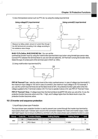
1: FDT-1
This inspects whether the output frequency of the inverter has reached the frequency set by the user. It begins to
operate when the following condition is met.
absolute value(set frequency – output frequency) < detected frequency width/2
The detected frequency width is set as follows and the illustration below shows the frequency width having been
set at 10Hz.
Group Code No. Function Display Initial Setting Unit
OUT 58 FDT Band (Hz) - 10.00 Hz
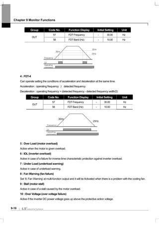
2 : FDT-2
Active when the frequency set by the user is equal to the FDT Frequency and the No. 0 FDT-1 condition above
is simultaneously met.
[absolute value(set frequency – detected frequency) < detected frequency width /2 ] & [ FDT-1 ]
This case assumes that the detected frequency width is 10Hz and the detected frequency is 30Hz.
Group Code No. Function Display Initial Setting Unit
57 FDT Frequency - 30.00 Hz
OUT
58 FDT Band (Hz) - 10.00 Hz
3 : FDT-3
Active when the operating frequency meets the following condition.
absolute value(detected frequency – output frequency) < detected frequency width /2
15Hz
Set
Frequency
Frequency
Q1
20Hz
20Hz
40Hz
35Hz
Operating
command
40Hz
25Hz
Frequency
Q1
30Hz
50Hz
Operating
command
Set
Frequency](https://image.slidesharecdn.com/is7eng101201-140613211330-phpapp02/85/I-s7-eng_101201-192-320.jpg)


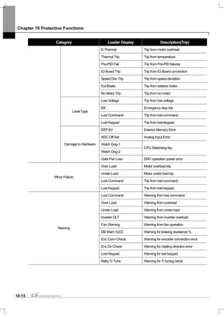
![Chapter 10 Protective Functions
10-1
10.1 Protective Functions
The protective functions provided by the SV-iS7 series are broadly divided into two types. One is for protecting from
overheat and damage and the other is for protecting from the inverter itself and preventing malfunction.
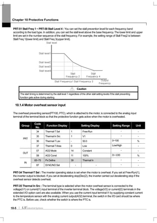
10.1.1 Motor protection
1) Electronic thermal (Preventing motor overheat)
The electronic thermal function is automatically predicting temperature rises using the inverter output current
without a temperature sensor and providing protection suited to the inverse time thermal characteristic of the
motor.
Group Code No. Function Display Setting Display Setting Range Unit
40 ETH Trip Sel 0 None None/Free-Run/Dec -
41 Motor Cooling 0 Self-cool - -
42 ETH 1min - 150 120~200 %
PRT
43 ETH Cont - 120 50~180 %
PRT-40 ETH Trip Sel : You can select the inverter operation in case of electronic thermal protective operation.
On the keypad, the failure status is displayed as E-Thermal.
0 : None
The electronic thermal function is not active.
1 : Free-Run (Free Run)
The inverter output is blocked and the motor does free run.
2 : Dec (Deceleration)
Stop after deceleration.
PRT-41 Motor Cooling : selects the operating method of the cooling fan mounted on the motor.
0 : Self-cool
The cooling fan connected to the motor axis, the cooling effect varies according to the rotation speed. Most
general induction motors have such a structure.
1 : Forced-cool
This structure supplies separate power to the cooling fan. This applies to the load that should operate for a long
time at a low speed and the motor exclusively for the inverter has such a structure.
PRT-42 ETH 1min : inputs the amount of current that can flow continuously for a minute on the basis of the rated
current (BAS-13) of the motor.
PRT-43 ETH Cont : sets the magnitude of the current at which the electronic thermal protective function
becomes active. Incessant operation is available without protection below the set value.
Continuously permitted current[%]
100
95
65
20 60
Frequency[Hz]
PRT-41=0
PRT-41=1
Current[%]
PRT-42
60 Electronic thermal time(sec)
PRT-43](https://image.slidesharecdn.com/is7eng101201-140613211330-phpapp02/85/I-s7-eng_101201-199-320.jpg)


![Chapter 10 Protective Functions
10-10
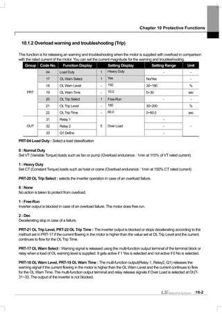
10.1.9 Braking resistance use rate setting
The iS7 series is divided into a model in which the braking circuit is built and the other in which a separate external
braking unit should be installed. 0.75~22kW belongs to the former(braking resistance unit excluded) and for those
above 30kW, you should install a braking unit on the exterior of the inverter. Therefore the function of limiting the
braking resistance use rate is necessary for only models below 22kW.
Group Code No. Function Display Setting Display Setting Range Unit
PRT 66 DB Warn %ED - 10 0~30% -
OUT 31~33 Relay1,2, Q1 31 DB Warn%ED - -
PRT-66 DB Warn %ED : sets the use rate of the resistance unit (%ED : Enshalt Daur). The resistance unit use rate
sets the ratio of operation of the braking resistance within an operating cycle. Continuous braking resistance is
available up to 15 seconds and after 15 seconds lapses, the inverter does not release any braking resistance use
signal.
Caution
Be careful when you use the braking resistance above the consumed electric power(Watt) of the braking resistance unit because
it might cause a fire due to overheated resistance. If you use a resistance unit with a heat sensor, you can use the sensor output
as the external failure signal of the multi-function input terminal.
Example 1) [%]100
____
_
% ×
+++
=
stopTdecTsteadyTaccT
decT
ED
Where,
T_acc : Lead time which accelerate to its set frequency
T_steady : Time which drive under constant speed at its set frequency
T_dec : Time which reduce to lower frequencies than its constant speed frequency Or Time which comes to a
stop from its constant speed frequency.
T_stop : Time which stay idle until another start
Example 2) [%]100
2__1__
_
% ×
+++
=
steadyTaccTsteadyTdecT
decT
ED
Frequency
T_acc
T_steady1
T_dec
T_steady2
Frequency
T_acc T_steady T_dec T_stop](https://image.slidesharecdn.com/is7eng101201-140613211330-phpapp02/85/I-s7-eng_101201-208-320.jpg)


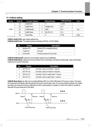


![Chapter 11 Communication Function
11-9
11.2 Communication Protocol
11.2.1 LS INV 485 protocol
Computer and other hosts are the master and the inverter is the slave. The slave inverter responds to the master’s
request for writing/reading.
[Basic Form]
Request:
ENQ Address No. CMD Data SUM EOT
1 byte 2 bytes 1 byte n bytes 2 bytes 1 byte
Normal Response:
ACK Address No. CMD Data SUM EOT
1 byte 2 bytes 1 byte n * 4 bytes 2 bytes 1 byte
Error response:
NAK Address No. CMD Error Code SUM EOT
1 byte 2 bytes 1 byte 2 bytes 2 bytes 1 byte
Description:
Requests begin with ENQ and end with EOT.
Normal responses begin withACK and ends with EOT.
Error responses begin with NAK and ends with EOT.
Address No. refers to the inverter No. and represented by 2 byteASCII-HEX.
(ASCII-HEX: hex representation consisting of ‘0’~ ‘9’, ‘A’ ~ ‘F’)
CMD: in capitals (IF Error if in small letters)
Character ASCII-HEX Command
‘R’ 52h Read
‘W’ 57h Write
‘X’ 58h Monitor registration request
‘Y’ 59h Monitor registration implementation
Data: represented inASCII-HEX
E.g.) If data value is 3,000: 3000 → ‘0’’B’’B’’8’h → 30h 42h 42h 38h
Error code: two can be displayedASCII (20h ~ 7Fh)
Transmission/reception buffer magnitude: transmission = 39 byte, reception = 44 byte
Monitor registration buffer: 8 Word
SUM: inspection by making sum to check communication errors
SUM =ASCII-HEX form of the 8 lowest bits of (Address No. + CMD + data)](https://image.slidesharecdn.com/is7eng101201-140613211330-phpapp02/85/I-s7-eng_101201-222-320.jpg)

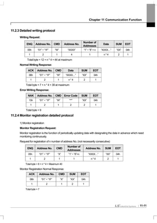
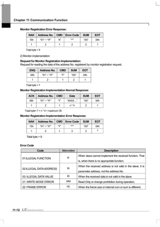
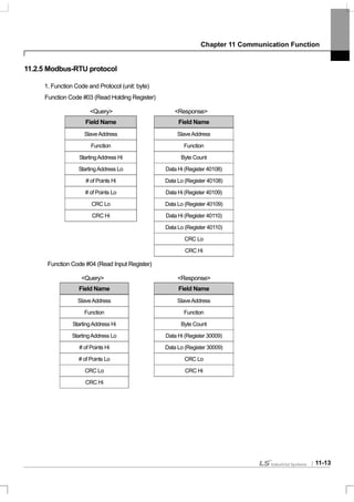


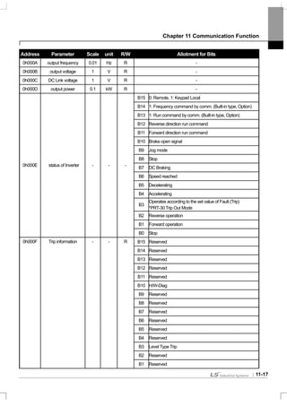
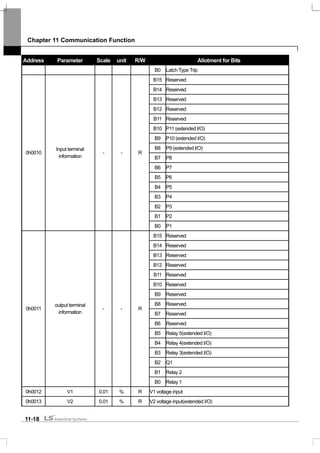


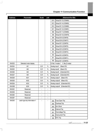


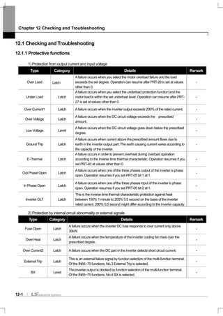


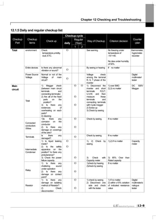
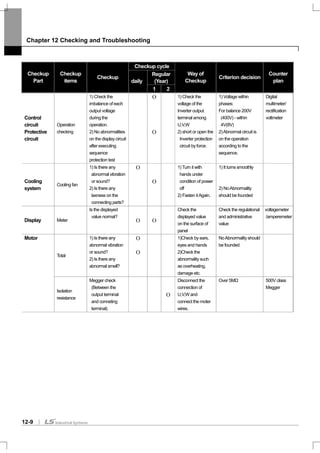
![Chapter 13 Table of Functions
13-1
13.1 Table of Functions
13.1.1 Parameter mode – DRV group ( DRV)
DRV Group (PAR DRV)
Note1)
Control Mode
No.
Communi
-cation
No.
Function Display Name Setting Range Initial Value
Shift
in
Opera-
tion
Page
V
/
F
S
L
V
C
S
L
T
V
C
T
00 - Jump Code jump code 0~99 9 O O O O O O
01 0h1101 Cmd Frequency
target
frequency
0~maximum
frequency[Hz]
0.0 O 7-1 O O O X X
02 0h1102 Cmd Torque
torque
command
-180~180[%] 0.0 O 8-31 X X X O O
Below75kW 20.0
03 0h1103 Acc Time
accelerating
time
0~600[sec]
Above90kW 60.0
O 7-20 O O O O O
Below75kW 30.0
04 0h1104 Dec Time
decelerating
time
0~600[sec]
Above90kW 90.0
O 7-20 O O O O O
0 Keypad
1 Fx/Rx-1
2 Fx/Rx-2
3 Int 485
4 Field Bus
06 0h1106 Cmd Source
operating
command
method
5 PLC
1:Fx/Rx-1 X 7-11 O O O O O
0 Keypad-1
1 Keypad-207 0h1107 Freq Ref Src
frequency
setting
method 2 V1
X 7-1 O O O X X
3 I1
4 V2
5 I2
6 Int 485
7 Encoder
08 0h1108 Trq Ref Src
torque
command
method
8 Fied Bus
0:Keypad-1
X 8-32 X X X O O
0 V/F 7-20
1 V/F PG 8-20
2 SlipCompen 8-11
3 Sensorless-1 8-21
4 Sensorless-2 8-23
09
Note1) 0h1109 Control Mode control mode
5 Vector
0:V/F X
8-27
O O O O O
* The grey code refers to hidden code, emerging only in case of setting of the code.
Note1)
Effectiveness of each code according to the Control Mode setting
V/F: V/Fmode (PG included), SL: Sensorless-1, 2 mode, VC: Vector mode, SLT: Sensorless-1, 2 Torque mode,
VCT: Vector Torque mode
Refer to Option manual for options.](https://image.slidesharecdn.com/is7eng101201-140613211330-phpapp02/85/I-s7-eng_101201-252-320.jpg)
![Chapter 13 Table of Functions
13-2
DRV Group (PAR DRV)
Control Mode
No.
Communi-
cation No.
Function Display Name Setting Range Initial Value
Shiftin
Opera-
tion
Page V
/
F
S
L
V
C
S
L
T
V
C
T
0 No
10 0h110A Torque Control
torque
control 1 Yes
0: No X 8-31 X X X O O
11 0h110B Jog Frequency
jog
frequency
0.5~maximum
frequency[Hz]
10.00 O 8-4 O O O O O
12 0h110C JogAcc Time
jog
operation
Acc time
0~600[sec] 20.0 O 8-4 O O O O O
13 0h110D Jog Dec Time
jog
operation
Dec time
0~600[sec] 30.0 O 8-4 O O O X X
8-11
14 0h110E Motor Capacity
motor
capacity
0:0.2kW, 1:0.4kW
2:0.75kW, 3:1.5kW
4:2.2kW, 5:3.7kW
6:5.5kW, 7:7.5kW
8:11kW, 9:15kW
10:18.5kW, 11:22kW
12:30kW, 13:37kW
14:45kW, 15:55kW
16:75kW, 17:90kW
18:110kW,
19:132kW
20:160kW,
21:185kW
depends on
inverter
capacity
X
8-17
O O O O O
0 Manual
15 0h110F Torque Boost
torque
boost
method 1 Auto
0:Manual X 7-22 O X X X X
Below75kW 2.016
Note2)
0h1110 Fwd Boost
forward
torque
boost
0~15[%]
Above90kW 1.0
X 7-22 O X X X X
Below75kW 2.0
17 0h1111 Rev Boost
reverse
torque
boost
0~15[%]
Above90kW 1.0
X 7-22 O X X X X
18 0h1112 Base Freq
base
frequency
30~400[Hz] 60.00 X 7-20 O O O O O
19 0h1113 Start Freq
starting
frequency
0.01~10[Hz] 0.50 X 7-20 O X X X X
20 0h1114 Max Freq
maximum
frequency
40~400 60.00 X 7-26 O O O O O
0 Hz Display
21 0h1115 Hz/Rpm Sel
speed unit
selection 1 Rpm Display
0:Hz O 9-4 O O O O O
* The grey code refers to hidden code, emerging only in case of setting of the code.
Note2)
DRV-16~17 code is displayed only when DRV-15 (Torque Boost) code value is “Manual”.](https://image.slidesharecdn.com/is7eng101201-140613211330-phpapp02/85/I-s7-eng_101201-253-320.jpg)
![Chapter 13 Table of Functions
13-3
13.1.2 Parameter mode – Basic function group ( BAS)
BAS Group(PAR BAS)
Control Mode
No.
Communi
-cation
No.
Function
Display
Name Setting Range Initial Value
Shiftin
Opera-
tion
Page V
/
F
S
L
V
C
S
L
T
V
C
T
00 - Jump Code jump code 0~99 20 O O O O O O
0 None
1 V1
2 I1
3 V2
01 0h1201 Aux Ref Src
auxiliary
command
setting
method
4 I2
0:None X 8-1 O O O X X
0 M+(G*A)
1 M*(G*A)
2 M/(G*A)
3 M+(M*(G*A))
4 M+G*2(A-50%)
5 M*(G*2(A-50%))
6 M/(G*2(A-50%))
02
Note3) 0h1202
Aux Calc
Type
auxiliary
command
movement
selection
7 M+M*G*2(A-50%)
0: M+(G*A) X 8-1 O O O X X
03 0h1203 Aux Ref Gain
auxiliary
command
gain
-200.0 ~ 200.0[%] 100.0 O 8-2 O O O X X
0 Keypad
1 Fx/Rx-1
2 Fx/Rx-2
3 Int 485
4 FieldBus
04 0h1204 Cmd 2nd Src
2nd operation
command
method
5 PLC
1: Fx/Rx-1 X 7-28 O O O O O
05 0h1205 Freq 2nd Src
2nd
frequency
Setting
method
0 Keypad-1 0:Keypad-1 O 7-28 O O O X X
* The grey code refers to hidden code, emerging only in case of setting of the code.
Note3)
BAS-02 code is displayed only when BAS-01 (Aux Ref Src) code has a value other than “NONE”.](https://image.slidesharecdn.com/is7eng101201-140613211330-phpapp02/85/I-s7-eng_101201-254-320.jpg)
![Chapter 13 Table of Functions
13-4
BAS Group (PAR BAS)
Control Mode
No.
Commu
nication
No.
Function
Display
Name Setting Range Initial Value
Shift
in
Opera-
tion
Page V
/
F
S
L
V
C
S
L
T
V
C
T
1 Keypad-2
2 V1
3 I1
4 V2
5 I2
6 Int 485
7 Encoder
8 FieldBus
9 PLC
10 Synchro
11 BinaryType
06 0h1206 Trq 2nd Src
2nd
torque
command method
12 Keypad-2
0:
Keypad-1
O 7-28 X X X O O
0 Linear
1 Square
2 User V/F
07 0h1207 V/F Pattern V/F pattern
3 Square2
0:Linear X 7-21 O O X X X
0 Max Freq
08 0h1208 Ramp T Mode
Acc/Dec standard
frequency 1 Delta Freq
0:Max Freq X 7-15 O O O X X
0 0.01 sec
1 0.1 sec09 0h1209 Time Scale time unit setting
2 1 sec
1:0.1 sec X 7-16 O O O X X
0 60Hz X
10 0h120A 60/50 Hz Sel
input power
frequency 1 50Hz
0:60Hz 8-43 O O O O O
11 0h120B Pole Number motor pole 2~48 X O O O O O
12 0h120C Rated Slip rated sleep speed 0~3000[rpm] X O O O O O
13 0h120D Rated Curr motor rated current 1~200[A] X O O O O O
14 0h120E Noload Curr
motor
no load current
0.5~200[A]
It depends
on inverter
capacity
X O O O O O
15 0h120F Rated Volt motor rated voltage 180~480[V] 0 X O O O O O
16 0h1210 Efficiency motor efficiency 70~100[%] X O O O O O
17 0h1211 Inertia Rate load inertial ratio 0~8 X
8-11
O O O O O
18 0h1212 Trim Power %
Power display
adjustment
70~130[%]
It depends
on inverter
capacity O 9-3 O O O O O
220V 220
19 0h1213
AC
Input Volt
input power voltage
170~230[V]
380~480[V] 440V 380
O 8-43 O O O O O
0 None
1 All
2 ALL(Stdstl)
3 Rs+Lsigma
4 Enc Test
5 Tr
20 -
Auto
Tuning
auto tuning
6 Tr(Stdstl)
0:None X 8-17 X O O O O](https://image.slidesharecdn.com/is7eng101201-140613211330-phpapp02/85/I-s7-eng_101201-255-320.jpg)
![Chapter 13 Table of Functions
13-5
BAS Group (PAR BAS)
Control Mode
No.
Commun
ication
No.
Function
Display
Name Setting Range
Initial
Value
Shiftin
Opera-
tion
Page V
/
F
S
L
V
C
S
L
T
V
C
T
21 - Rs stator resistance It depends on motor - X 8-19 X O O O O
22 - Lsigma leak inductance It depends on motor - X 8-19 X O O O O
23 - Ls stator inductance It depends on motor - X 8-19 X O O O O
24
Note4) - Tr rotor time constant 25~5000[msec] - X 8-19 X O O O O
41
Note5) 0h1229 User Freq 1 user frequency 1
0~maximum
frequency[Hz]
15.00 X 7-21 O X X X X
42 0h122A User Volt 1 user voltage 1 0~100[%] 25 X 7-21 O X X X X
43 0h122B User Freq 2 user frequency 2
0~maximum
frequency[Hz]
30.00 X 7-21 O X X X X
44 0h122C User Volt 2 user voltage 2 0~100[%] 50 X 7-21 O X X X X
45 0h122D User Freq 3 user frequency 3
0~maximum
frequency[Hz]
45.00 X 7-21 O X X X X
46 0h122E User Volt 3 user voltage 3 0~100[%] 75 X 7-21 O X X X X
47 0h122F User Freq 4 user frequency 4
0~maximum
frequency[Hz]
60.00 X 7-21 O X X X X
48 0h1230 User Volt 4 user voltage 4 0~100[%] 100 X 7-21 O X X X X
50
Note6) 0h1232 Step Freq-1
multi-step speed
frequency 1
0~maximum
frequency[Hz]
10.00 O 7-9 O O O X X
51 0h1233 Step Freq-2
multi-step speed
frequency 2
0~maximum
frequency[Hz]
20.00 O 7-9 O O O X X
52 0h1234 Step Freq-3
multi-step speed
frequency 3
0~maximum
frequency[Hz]
30.00 O 7-9 O O O X X
53 0h1235 Step Freq-4
multi-step speed
frequency 4
0~maximum
frequency[Hz]
40.00 O 7-9 O O O X X
54 0h1236 Step Freq-5
multi-step speed
frequency 5
0~maximum
frequency[Hz]
50.00 O 7-9 O O O X X
55 0h1237 Step Freq-6
multi-step speed
frequency 6
0~maximum
frequency[Hz]
60.00 O 7-9 O O O X X
56 0h1238 Step Freq-7
multi-step speed
frequency 7
0~maximum
frequency[Hz]
60.00 O 7-9 O O O X X
57 0h1239 Step Freq-8
multi-step speed
frequency 8
0~maximum
frequency[Hz]
55.00 O 7-9 O O O X X
58 0h123A Step Freq-9
multi-step speed
frequency 9
0~maximum
frequency[Hz]
50.00 O 7-9 O O O X X
59 0h123B Step Freq-10
multi-step speed
frequency 10
0~maximum
frequency[Hz]
45.00 O 7-9 O O O X X
60 0h123C Step Freq-11
multi-step speed
frequency 11
0~maximum
frequency[Hz]
40.00 O 7-9 O O O X X
61 0h123D Step Freq-12
multi-step speed
frequency 12
0~maximum
frequency[Hz]
35.00 O 7-9 O O O X X
62 0h123E Step Freq-13
multi-step speed
frequency 13
0~maximum
frequency[Hz]
25.00 O 7-9 O O O X X
63 0h123F Step Freq-14
multi-step speed
frequency 14
0~maximum
frequency[Hz]
15.00 O 7-9 O O O X X
64 0h1240 Step Freq-15
multi-step speed
frequency 15
0~maximum
frequency[Hz]
5.00 O 7-9 O O O X X
70 0h1246 Acc Time-1 multi-step 0~600[sec] 20.0 O 7-17 O O O X X](https://image.slidesharecdn.com/is7eng101201-140613211330-phpapp02/85/I-s7-eng_101201-256-320.jpg)
![Chapter 13 Table of Functions
13-6
Control Mode
No.
Commun
ication
No.
Function
Display
Name Setting Range
Initial
Value
Shiftin
Opera-
tion
Page V
/
F
S
L
V
C
S
L
T
V
C
T
accelerating time 1
71 0h1247 Dec Time-1
multi-step
decelerating time 1
0~600[sec] 20.0 O 7-17 O O O X X
72
Note7) 0h1248 Acc Time-2
multi-step
accelerating time 2
0~600[sec] 30.0 O 7-17 O O O X X
73 0h1249 Dec Time-2
multi-step
decelerating time 2
0~600[sec] 30.0 O 7-17 O O O X X
74 0h124A Acc Time-3
multi-step
accelerating time 3
0~600[sec] 40.0 O 7-17 O O O X X
75 0h124B Dec Time-3
multi-step
decelerating time 3
0~600[sec] 40.0 O 7-17 O O O X X
* The grey code refers to hidden code, emerging only in case of setting of the code.
Note4)
BAS-24 is shown only when DRV-09 Control Mode is “Sensorless-2” or “Vector”.
Note5)
BAS-41~48 is displayed only when it is set as “User V/F” even if there is only one BAS-07 or M2-V/F Patt (M2-25).
Note6)
IN-50~64 is displayed only when it is set as “multi-step speed”(Speed –L.M.H,X) even if there is only one among multi-function
input IN-65~72.
Note7)
displayed only when it is set as “multi-stepAcc/Dec”(Xcel-L,M,H) even if there is only one among IN-72~75 multi-function input](https://image.slidesharecdn.com/is7eng101201-140613211330-phpapp02/85/I-s7-eng_101201-257-320.jpg)
![Chapter 13 Table of Functions
13-7
13.1.3 Parameter mode – Extended function group
(PAR ADV)
Extended Function Group (PAR ADV)
Control Mode
No.
Communi
cation
No.
Function Display Name Setting Range
Initial
Value
Shift
in
Oper
ation
Page V
/
F
S
L
V
C
S
L
T
V
C
T
00 - Jump Code jump code 0~99 24 O - O O O O O
01 0h1301 Acc Pattern accelerating pattern 0 Linear X 7-18 O O O X X
02 0h1302 Dec Pattern decelerating pattern 1 S-curve
0:Linear
X 7-18 O O O X X
03 0h1303 Acc S Start
S accelerating starting
slope
1~100[%] 40 X 7-18 O O O X X
04 0h1304 Acc S End S accelerating end slope 1~100[%] 40 X 7-18 O O O X X
05 0h1305 Dec S Start
S decelerating starting
slope
1~100[%] 40 X 7-18 O O O X X
06 0h1306 Dec S End S decelerating end slope 1~100[%] 40 X 7-18 O O O X X
0 Acc
07 0h1307 Start Mode starting method
1 Dc-Start
0:Acc X 7-24 O O O X X
0 Dec
1 Dc-Brake
2 Free-Run
3 Flux Braking
08 0h1308 Stop Mode stop method
4 Powr Braking
0:Dec X 7-25 O O O X X
0 None
1 Forward Prev09 0h1309 Run Prevent
rotation preventing
direction selection
2 Reverse Prev
0:Non
e
X 7-14 O O O X X
0 No
10 0h130A Power-on Run power input starting
1 Yes
0:No O 7-14 O O O X X
12
Note8) 0h130C Dc-Start Time starting DC braking time 0~60[sec] 0.00 X 7-24 O O O X X
13 0h130D Dc Inj Level DC supply 0~200[%] 50 X 7-24 O O O X X
14
Note9) 0h130E Dc-Block Time
Pre-DC braking output
block time
0~60[sec] 0.10 X 7-25 O O O X X
15 0h130F Dc-Brake Time DC braking time 0~60[sec] 1.00 X 7-25 O O O X X
16 0h1310 Dc-Brake Level DC braking 0~200[%] 50 X 7-25 O O O X X
17 0h1311 Dc-Brake Freq DC braking frequency
startingfrequency~
60[Hz]
5.00 X 7-25 O O O X X
20 0h1314 Acc Dwell Freq
Accelerating dwell
frequency
Starting frequency
~maximum
frequency[Hz]
5.00 X 8-9 O O O X X
21 0h1315 Acc Dwell Time
Accelerating dwell
operation time
0~60.0[sec] 0.00 X 8-9 O O O X X
22 0h1316 Dec Dwell Freq
Decelerating dwell
frequency
Starting frequency
~maximum
frequency[Hz]
5.00 X 8-9 O O O X X
23 0h1317 Dec Dwell Time
Decelerating dwell
operation time
0~60.0[sec] 0.00 X 8-9 O O O X X
* The grey code refers to hidden code, emerging only in case of setting of the code.
Note8)
ADV-12 is displayed only whenADV-07 “Stop Mode” is set as “Dc-Start”.
Note9)
ADV-14~17 is displayed only whenADV-08 “Stop Mode” is set as “DC-Brake”.](https://image.slidesharecdn.com/is7eng101201-140613211330-phpapp02/85/I-s7-eng_101201-258-320.jpg)
![Chapter 13 Table of Functions
13-8
Extended Function Group (PAR ADV)
Control Mode
No.
Communication
No.
Function
Display
Name Setting Range
Initial
Value
Shift in
Operation
Page V
/
F
S
L
V
C
S
L
T
V
C
T
0 No
24 0h1318 Freq Limit frequency limit
1 Yes
0:No X 7-27 O O O X X
25
Note10) 0h1319 Freq Limit Lo
frequency lower
limit
0~upper limit[Hz] 0.50 O 7-27 O O O X X
26 0h131A Freq Limit Hi
frequency upper
limit
0.5~maximum
frequency[Hz]
60.00 X 7-27 O O O X X
0 No
27 0h131B Jump Freq frequency jump
1 Yes
0:No X 7-27 O O O X X
28
Note11) 0h131C Jump Lo 1
jump frequency
lower limit 1
0~jumpfrequencyupper
limit1[Hz]
10.00 O 7-27 O O O X X
29 0h131D Jump Hi 1
jump frequency
upper limit 1
Jump frequency lower
limit1
~maximum
frequency[Hz]
15.00 O 7-27 O O O X X
30 0h131E Jump Lo 2
jump frequency
lower limit 2
0~jumpfrequency
upper limit2[Hz]
20.00 O 7-27 O O O X X
31 0h131F Jump Hi 2
jump frequency
upper limit 2
Jump frequency lower
limit2
~maximum
frequency[Hz]
25.00 O 7-27 O O O X X
32 0h1320 Jump Lo 3
jump frequency
lower limit 3
0~jumpfrequency
upper limit3[Hz]
30.00 O 7-27 O O O X X
33 0h1321 Jump Hi 3
jump frequency
upper limit 3
Jump frequency lower
limit3
~maximum
frequency[Hz]
35.00 O 7-27 O O O X X
41
Note12) 0h1329 BR Rls Curr brake open current 0~180.0[%] 50.0 O 8-52 O O O X X
42 0h132A BR Rls Dly
brake open delay
time
0~10.00[sec] 1.00 X 8-52 O O O X X
44 0h132C
BR Rls Fwd
Fr
brake open
forward frequency
0~maximum
frequency[Hz]
1.00 X 8-52 O O O X X
45 0h132D
BR Rls Rev
Fr
brake open
reverse frequency
0~maximum
frequency[Hz]
1.00 X 8-52 O O O X X
46 0h132E BR Eng Dly
brake close delay
time
0~10[sec] 1.00 X 8-52 O O O X X
47 0h132F BR Eng Fr
brake close
frequency
0~maximum
frequency[Hz]
2.00 X 8-52 O O O X X
0 None
1 Manual50 0h1332 E-Save Mode
energy saving
operation
2 Auto
0:None X 8-34 O O X X X
51
Note13) 0h1333 Energy Save
energy saving
amount
0~30[%] 0 O 8-34 O O O X X
60 0h133C
Xcel Change
Fr
Acc/Dec time
exchange
frequency
0~maximum
frequency[Hz]
0.00 X 7-17 O O O X X
* The grey code refers to hidden code, emerging only in case of setting of the code.
Note10)
ADV-25~26 is displayed only whenADV-24 (Freq Limit) is set as “Freq Limit”.
Note11)
ADV-28~33 is displayed only whenADV-27 (Jump Freq) set as “Yes”.
Note12)
ADV-41~47 is displayed only when a code of OUT-31~33 is set as “BR Control”.
Note13)
ADV-51 is displayed only whenADV-50 (E-Save Mode) is set as values other than “None”.](https://image.slidesharecdn.com/is7eng101201-140613211330-phpapp02/85/I-s7-eng_101201-259-320.jpg)
![Chapter 13 Table of Functions
13-9
Extended function Group (PAR ADV)
Control Mode
No.
Communication
No.
Function
Display
Name Setting Range Initial Value
Shift in
Operation
Page V
/
F
S
L
V
C
S
L
T
V
C
T
61 - Load Spd Gain
revolution
display gain 1~6000.0[%] 100.0 O 9-3 O O O X X
0 x 1
1 x 0.1
2 x 0.01
3 x 0.001
62 -
Load Spd
Scale
revolution
display scale
4 x 0.0001
0:x 1 O 9-3 O O O X X
0 rpm
63 0h133F Load Spd Unit
revolution
display unit 1 mpm
0:rpm O 9-3 O O O O O
0 During Run
1 Always ON64 0h1340 FAN Control
cooling fan
control
2 Temp Control
0:During
Run
O 8-42 O O O X X
0 No
65 0h1341
U/D Save
Mode
up/down
Operation
frequency
saving 1 Yes
0:No O 8-6 O O O X X
0 None
1 V1
2 I1
3 V2
66 0h1342 On/Off Ctrl Src
4 I2
0:None X 8-55 O O O O O
67 0h1343 On-C Level
Output contact
point ON level 10~100[%] 90.00 X 8-56 O O O O O
68 0h1344 Off-C Level
Output contact
point OFF level
-100.00~output
contact point ON
level[%]
10.00 X 8-56 O O O O O
0 Always Enable
70 0h1346 Run En Mode
safety
operation
selection 1 DI Dependent
0:Always
Enable
X 8-98 O O O O O
0 Free-Run
1 Q-Stop71
Note14) 0h1347 Run Dis Stop
safety
operation stop
method 2
Q-Stop
Resume
0:Free-Run X 8-8 O O O O O
72 0h1348 Q-Stop Time
safety
operation
decelerating
time
0~600.0[sec] 5.0 O 8-8 O O O O O
0 No
74 0h134A RegenAvd Sel
Selection of
avoidance of
regeneration
function for
press
1 Yes
No X 8-60 O O O O O
200V: 300~400 350V
75 0h134B
RegenAvd
Level
Operational
Voltage level of
avoidance of
regeneration for
press
400V: 600~800 700V
X 8-60 O O O X X](https://image.slidesharecdn.com/is7eng101201-140613211330-phpapp02/85/I-s7-eng_101201-260-320.jpg)
![Chapter 13 Table of Functions
13-10
Control Mode
No.
Communication
No.
Function
Display
Name Setting Range Initial Value
Shift in
Operation
Page V
/
F
S
L
V
C
S
L
T
V
C
T
76
Note15) 0h134C
CompFreq
Limit
Restriction of
compensational
frequency of
avoidance of
regeneration for
press
0~ 10.00Hz 1.00[Hz] X 8-60 O O O X X
77 0h134D
RegenAvd
Pgain
P-gain of
avoidance of
regeneration for
press
0 ~ 100.0% 50.0[%] O 8-60 O O O X X
78 0h134E
RegenAvd
Igain
I-gain of
avoidance of
regeneration for
press
20~30000[msec] 500[msec] O 8-60 O O O X X
* The grey code refers to hidden code, emerging only in case of setting of the code.
Note14)
ADV-71~72 is displayed only whenADV-70 (Run En Mode) is set as “DI Dependent”.
Note15)
ADV-76~78 is displayed only whenADV-75 (RegenAvd Sel) is set as “Yes”.](https://image.slidesharecdn.com/is7eng101201-140613211330-phpapp02/85/I-s7-eng_101201-261-320.jpg)
![Chapter 13 Table of Functions
13-11
13.1.4 Parameter mode – Control function group ( CON)
Control Function Group (PAR CON)
Control Mode
No.
Communication
No.
Function
Display
Name Setting Range
Initial
Value
Shift in
Operation
Page V
/
F
S
L
V
C
S
L
T
V
C
T
00 - Jump Code jump code 0~99 51 O O O O O O
Below22kW 0.7~15[kHz] 5.0
30~45kW 0.7~10[kHz] 5.0
55~75kW 0.7~7[kHz] 5.0
90~110kW 0.7~6[kHz] 3.0
04 0h1404 Carrier Freq carrier frequency
132~160kW 0.7~5[kHz] 3.0
O 8-38 O O O O O
0 Normal PWM
05 0h1405 PWM Mode switching mode
1 Lowleakage PWM
0:Normal
PWM
X 8-38 O O O O O
09 0h1409 PreExTime
Initial excitation
time
0~60[sec] 1.00 X 8-27 X X O O O
10 0h140A Flux Force
Initial excitation
power supply
100~500[%] 100.0 X 8-27 X X O O O
11 0h140B Hold Time
permanent
operation
sustaining time
0~60[sec] 1.00 X 8-27 X X O X X
12 0h140C
ASR P
Gain 1
speed control
period
proportional
gain1
10~500[%] 50.0 O 8-27 X X O X X
13 0h140D
ASR I
Gain 1
speed control
period integral
calculus gain1
10~9999[msec] 300 O 8-27 X X O X X
15 0h140F
ASR P
Gain 2
speed control
period
proportional
gain2
10~500[%] 50.0 O 8-27 X X O X X
16 0h1410
ASR I
Gain 2
speed control
period integral
calculus gain2
10~9999[msec] 300 O 8-27 X X O X X
18 0h1412
Gain SW
Freq
gain exchange
frequency
0~120[Hz] 0.00 X 8-27 X X O X X
19 0h1413
Gain Sw
Delay
gain exchange
time
0~100[sec] 0.10 X 8-27 X X O X X
0 No
20 0h1414
SL2 G
View Sel
sensorless2 2nd
gain display
setting 1 Yes
0:No O 8-23 X X X X X
21 0h1415
ASR-SLP
Gain1
sensorless1,2
speed control
period
proportional
gain1
0~5000[%]
Depends
on motor
capacity
O 8-23 X O X X X
22 0h1416
ASR-SLI
Gain1
sensorless1,2
speed control
10~9999[msec]
Depends
on motor
O 8-23 X O X X X](https://image.slidesharecdn.com/is7eng101201-140613211330-phpapp02/85/I-s7-eng_101201-262-320.jpg)
![Chapter 13 Table of Functions
13-12
Control Mode
No.
Communication
No.
Function
Display
Name Setting Range
Initial
Value
Shift in
Operation
Page V
/
F
S
L
V
C
S
L
T
V
C
T
period integral
calculus gain1
capacity
23
Note
16)
0h1417
ASR-SLP
Gain2
sensorless2
speed control
period
proportional
gain2
1~1000[%]
Depends
on motor
capacity
O 8-23 X X X X X
24 0h1418
ASR-SLI
Gain2
sensorless2
speed control
period integral
calculus gain2
1~1000[%]
Depends
on motor
capacity
O 8-23 X X X X X
26 0h141A
Observer
Gain1
sensorless2
measurer gain1
0~30000 10500 O 8-23 X X X X X
27 0h141B
Observer
Gain2
sensorless2
measurer gain2
1~1000[%] 100.0 O 8-23 X X X X X
28 0h141C
Observer
Gain3
sensorless2
measurer gain3
0~30000 13000 O 8-23 X X X X X
29 0h141D
S-Est P
Gain1
sensorless2
speed estimator
proportional
gain1
0~30000
Depends
on motor
capacity
O 8-23 X X X X X
30 0h141E
S-Est I
Gain1
sensorless2
speed estimator
integral calculus
gain1
0~30000
Depends
on motor
capacity
O 8-23 X X X X X
* The grey code refers to hidden code, emerging only in case of setting of the code.
Note16)
CON-23~28, 31~32 are displayed only when DRV-09 (Control Mode) is “Sensorless2” and CON-20 (SL2 G View Sel) is set as
“YES”.](https://image.slidesharecdn.com/is7eng101201-140613211330-phpapp02/85/I-s7-eng_101201-263-320.jpg)
![Chapter 13 Table of Functions
13-13
Control Function Group (PAR CON)
Control Mode
No.
Commun
ication
No.
Function Display Name Setting Range
Initial
Value
Shift in
Opera
tion
Page V
/
F
S
L
V
C
S
L
T
V
C
T
31 0h141F S-Est P Gain2
Sensorless2 speed
estimator
proportional gain2
1~1000[%]
Depends
on motor
capacity
O 8-23 X X X X X
32 0h1420 S-Est I Gain2
Sensorless2 speed
estimator integral
calculus gain2
1~1000[%]
Depends
on motor
capacity
O 8-23 X X X X X
34 0h1422 SL2 OVM Perc
Sensorless2
overvoltage
modulation range
adjustment
100~180[%] 120 X 8-25 X O X X X
45
Note17) 0h142D PG P Gain
PG operation
proportional gain
0~9999 3000 O 8-20 O X X X X
46 0h142E PG I Gain
PG operation
integral calculus
gain
0~9999 50 O 8-20 O X X X X
47 0h142F PG Slip Max%
PG operation
maximum sleep
0~200 100 X 8-20 O X X X X
48 - ACR P Gain
Current control
period P gain
0~10000 1200 O 8-21 X O O O O
49 - ACR I Gain
Current control
period I gain
0~10000 120 O 8-21 X O O O O
51 0h1433 ASR Ref LPF
speed control
period
reference filter
0~20000[msec] 0 X 8-21 X O O X X
52 0h1434 Torque Out LPF
Torque control
period
Output filter
0~2000[msec] 0 X 8-27 X X X O O
0 Keypad-1
1 Keypad-2
2 V1
3 I1
4 V2
5 I2
6 Int 485
7 Encoder
8 FiedBus
9 PLC
10 Synchro
53 0h1435 Torque Lmt Src
Torque limit
Setting method
11 Binary Type
0:Keypa
d-1
X
8-27
X X X O O
54
Note18) 0h1436 FWD +Trq Lmt
forward offsetting
Torque limit 0~200[%] 180.0 O 8-27 X X X O O
55 0h1437 FWD –Trq Lmt
forward
regenerative
torque limit
0~200[%] 180.0 O 8-27 X X X O O
56 0h1438 REV +Trq Lmt
reverse offsetting
torque limit 0~200[%] 180.0 O 8-27 X X X O O
57 0h1439 REV –Trq Lmt
reverse
regenerative
torque limit
0~200[%] 180.0 O 8-27 X X X O O
* The grey code refers to hidden code, emerging only in case of setting of the code.](https://image.slidesharecdn.com/is7eng101201-140613211330-phpapp02/85/I-s7-eng_101201-264-320.jpg)
![Chapter 13 Table of Functions
13-14
Note17)
CON-45~47 are displayed when Encoder Board is inserted and Control mode is V/F PG.
Note18)
CON-54~57 are displayed only when DRV-09(Control Mode) is set as “Sensorless-1, 2” or “Vector”. In addition, initial value of
torque limit is changed to 150% whenADV-74 RegenAvd Level function sets.
Control Function Group (PAR CON)
1)Control Mode
No.
Communi-
cation No.
Function Display Name Setting Range Initial Value
Shift in
Opera-
tion
Page V
/
F
S
L
V
C
S
L
T
V
C
T
0 Keypad-1
1 Keypad-2
2 V1
3 I1
4 V2
5 I2
6 Int 485
7 FiedBus
58 0h143A Trq Bias Src
torque bias
setting method
8 PLC
0:Keypad-1 X 8-27 X X O X X
59 0h143B Torque Bias torque bias -120~120[%] 0.0 O 8-27 X X O X X
60 0h143C
Torque
Bias FF
torque bias
compensation
0~100[%] 0.0 O 8-27 X X O X X
0 Keypad-1
1 Keypad-2
2 V1
3 I1
4 V2
5 I2
6 Int 485
7 FiedBus
62 0h143D
Speed
Lmt Src
Speed limit setting
method
8 PLC
0:Keypad-1 O 8-31 X X X X O
63 0h143F
FWD Speed
Lmt
forward speed
limit
0~maximum
frequency[Hz] 60.00 O 8-31 X X X X O
64 0h1440
REV Speed
Lmt
reverse speed
limit
0~maximum
frequency[Hz] 60.00 O 8-31 X X X X O
65 0h1441
Speed Lmt
Gain
Speed limit
operation gain
100~5000[%] 500 O 8-32 X X X X O
66 0h1442 Droop Perc
droop operation
amount
0~100[%] 0.0 O 8-33 X X X X O
67
Note19) 0h1443 Droop St Trq droop start torque 0~100[%] 100.0 O 8-33 X X X X O
68 0h1444 SPD/TRQAcc T
torque mode
speed mode
exchange
accelerating time
0~600[sec] 20.0 O 8-33 X X X X O
69 0h1445 SPD/TRQAcc T
torque mode
speed mode
exchange
decelerating time
0~600[sec] 30.0 O 8-33 X X X X O
* The grey code refers to hidden code, emerging only in case of setting of the code.
Note19)
CON-67 is displayed only when Encoder option board is mounted.](https://image.slidesharecdn.com/is7eng101201-140613211330-phpapp02/85/I-s7-eng_101201-265-320.jpg)
![Chapter 13 Table of Functions
13-15
Control Function Group (PAR CON)
1)Control Mode
No.
Communi
cation No.
Function Display Name Setting Range Initial Value
Shift
in
Opera
tion
Page V
/
F
S
L
V
C
S
L
T
V
C
T
0 Flying Start - 1
70 0h1446 SS Mode
Selection of
Speed search
mode 1 Flying Start - 2
0 X - O O O X X
Bit 0000~1111
1
accelerating speed
searchselection
2 Resetstartaftertrip
3
Re-start after
instantaneous
interruption
71 0h1447 Speed Search
Speed search
operation
selection
4
Start immediately
afterpowerON
0000 X 8-35 O O O X X
Below75kW 150
72 0h1448 SS Sup-Current
speed search
standard current
80~200[%]
Above90kW 100
O 8-35 O O X X X
73 0h1449 SS P-Gain
speed search
proportional gain
0~9999 100 O 8-35 O O X X X
74 0h144A SS I-Gain
speed search
integral calculus
gain
0~9999 200 O 8-35 O O X X X
75 0h144B SS Block Time
Pre-speed
search output
block time
0~60[sec] 1.0 X 8-35 O O X X X
0 No
77 0h144D KEB Select
energy buffering
selection 1 Yes
0:No X 8-34 O O O X X
78
Note20) 0h144E KEB Start Lev
energy buffering
start amount
110~140[%] 125.0 X 8-34 O O O X X
79 0h144F KEB Stop Lev
energy buffering
stop amount
130~145[%] 130.0 X 8-34 O O O X X
80 0h1450 KEB Gain
energy buffering
gain
1~2000 1000 O 8-34 O O O X X
82
Note21) 0h1452 ZSD Frequency
permanent
detection
frequency
0~10[Hz] 2.00 O 9-12 X X O X O
83 0h1453 ZSD Band
permanent
detection
frequency band
0~2[Hz] 1.00 O 9-12 X X O X O
* The grey code refers to hidden code, emerging only in case of setting of the code.
Note20)
CON-78~80 are displayed only when CON-77 (KEB Select) is set as “Yes”.
Note21)
CON-82~83 are displayed only when DRV-09 (Control Mode) is set as “Vector”.](https://image.slidesharecdn.com/is7eng101201-140613211330-phpapp02/85/I-s7-eng_101201-266-320.jpg)
![Chapter 13 Table of Functions
13-16
13.1.5 Parameter mode – Input terminal block function group ( IN)
Input Terminal Block Function Group (PAR IN)
Control Mode
No.
Communi
cation No.
Function
Display
Name Setting Range
Initial
Value
Shift
in
Opera
tion
Pag
e
V
/
F
S
L
V
C
S
L
T
V
C
T
00 - Jump Code jump code 0~99 65 O - O O O O O
01 0h1501
Freq
at 100%
Analog maximum input
frequency
Starting
frequency~
maximum
frequency[Hz]
60.00 O 7-2 O O O X X
02 0h1502 Torque at100%
Analog maximum input
torque
0~200[%] 100.0 O 7-2
X X O O O
05 0h1505 V1 Monitor[V] V1 input amount display 0~10[V] 0.00 O 7-2 O O O O O
0 Unipolar
06 0h1506 V1 Polarity V1 input polar selection
1 Bipolar
0:
Unipolar
X 7-2 O O O O O
07 0h1507 V1 Filter
V1 input filter time
constant
0
~10000[msec]
10 O 7-2 O O O O O
08 0h1508 V1 Volt x1
V1input minimum
voltage
0~10[V] 0.00 O 7-2 O O O O O
09 0h1509 V1 Perc y1
V1minimum voltage
output %
0~100[%] 0.00 O 7-2 O O O O O
10 0h150A V1 Volt x2
V1input maximum
voltage
0~10[V] 10.00 O 7-2 O O O O O
11 0h150B V1 Perc y2
V1maximum voltage
output %
0~100[%] 100.00 O 7-2 O O O O O
12
Note22) 0h150C V1 (–)Volt x1’
V1(–)input minimum
voltage
-10~0[V] 0.00 O 7-4 O O O O O
13 0h150D V1(–)Perc y1’
V1(–)minimum voltage
output %
-100~0[%] 0.00 O 7-4 O O O O O
14 0h150E V1(–)Volt x2’
V1(–)input maximum
voltage
-10~0[V] -10.00 O 7-4 O O O O O
15 0h150F V1(–)Perc y2’
V1(–)maximum voltage
output %
-100~0[%] -100.00 O 7-4 O O O O O
0 No
16 0h1510 V1 Inverting rotation direction change
1 Yes
0: No O 7-2 O O O O O
17 0h1511 V1 Quantizing V1 quantization level 0.04~10[%] 0.04 X 7-2 O O O O O
20 0h1514 I1 Monitor[mA] I1input amount display 0~20[mA] 0.00 O 7-6 O O O O O
22 0h1516 I1 Filter
I1input filter time
constant
0 ~10000[msec] 10 O 7-6 O O O O O
23 0h1517 I1 Curr x1 I1input minimum current 0~20[mA] 4.00 O 7-6 O O O O O
24 0h1518 I1 Perc y1
Output at I1 minimum
current %
0~100[%] 0.00 O 7-6 O O O O O
25 0h1519 I1 Curr x2
I1input maximum
current
4~20[mA] 20.00 O 7-6 O O O O O
26 0h151A I1 Perc y2
Output at
I1maximumcurrent
0~100[%] 100.00 O 7-6 O O O O O
0 No
31 0h151F I1 Inverting rotation direction change
1 Yes
0: No O 7-6 O O O O O
32 0h1520 I1 Quantizing I1 quantization level 0.04~10[%] 0.04 O 7-6 O O O O O
Note22)
IN-12~15 codes are displayed only when IN-06 (V1 Polarity) is set as “Bipolar”.](https://image.slidesharecdn.com/is7eng101201-140613211330-phpapp02/85/I-s7-eng_101201-267-320.jpg)
![Chapter 13 Table of Functions
13-17
Input Terminal Block Function Group (PAR IN)
Control Mode
No.
Commu
nication
No.
Function
Display
Name Setting Range
Initial
Value
Shift
in
Oper
ation
Page V
/
F
S
L
V
C
S
L
T
V
C
T
35
Note23) 0h1523 V2 Monitor[V]
V2 input amount
display
0~10[V] 0.00 O 7-7 O O O O O
0 Unipolar
36 0h1524 V2 Polarity
V1 input polarity
selection 1 Bipolar
1:
Bipolar
O 7-7 O O O O O
37 0h1525 V2 Filter
V2 input filter time
constant
0~10000
[msec]
10 O 7-7 O O O O O
38 0h1526 V2 Volt x1
V2 input minimum
voltage
0~10[V] 0.00 O 7-7 O O O O O
39 0h1527 V2 Perc y1
output% at V2
minimum voltage
0~100[%] 0.00 O 7-7 O O O O O
40 0h1528 V2 Volt x2
V2 input maximum
voltage
0~10[V] 10.00 O 7-7 O O O O O
41 0h1529 V2 Perc y2
output% at V2
maximum voltage
0~100[%] 100.00 O 7-7 O O O O O
42 0h152A V2 –Volt x1’
V2 –input minimum
voltage
-10~0[V] 0.00 O 7-7 O O O O O
43 0h152B V2–Perc y1’
output% at V2–
minimum voltage
-100~0[%] 0.00 O 7-7 O O O O O
44 0h152C V2 –Volt x2’
V2 –input maximum
voltage
-10~0[V] -10.00 O 7-7 O O O O O
45 0h152F V2 –Perc y2’
output% at V2–
maximum voltage
-100~0[%] -100.00 O 7-7 O O O O O
0 No
46 0h1530 V2 Inverting
rotation direction
change 1 Yes
0:No O 7-7 O O O O O
47 0h1532 V2 Quantizing V2 quantization level 0.04~10[%] 0.04 O 7-7 O O O O O
50 0h1534 I2 Monitor[mA]
I2 input amount
display
0~20[mA] 0.00 O 7-8 O O O O O
52 0h1535 I2 Filter
I2 input filter time
constant
0~10000
[msec]
15 O 7-8 O O O O O
53 0h1536 I2 Curr x1
I2 input minimum
current
0~20[mA] 4.00 O 7-8 O O O O O
54 0h1537 I2 Perc y1
output% at I2
minimum current
0~100[%] 0.00 O 7-8 O O O O O
55 0h1538 I2 Curr x2
I2 input maximum
current
0~20[mA] 20.00 O 7-8 O O O O O
56 0h153D I2 Perc y2
output% at I2
maximum current
0~100[%] 100.00 O 7-8 O O O O O
0 No
61 0h153E I2 Inverting
rotation direction
change 1 Yes
0:No O 7-8 O O O O O
62 0h153F I2 Quantizing I2 quantization level 0.04~10[%] 0.04 O 7-8 O O O O O
* The grey code refers to hidden code, emerging only in case of setting of the code.
Note23)
IN-35~62 codes are displayed only when the extended IO board is mounted.](https://image.slidesharecdn.com/is7eng101201-140613211330-phpapp02/85/I-s7-eng_101201-268-320.jpg)

![Chapter 13 Table of Functions
13-19
Input Terminal Block Function Group (PAR IN)
Control Mode
No.
Commun
ication
No.
Function
Display
Name Setting Range
Initial
Value
Shift in
Opera
-tion
Page V
/
F
S
L
V
C
S
L
T
V
C
T
33 -Reserved- -
34 Pre Excite 8-30
35 Speed/Torque 8-31
36 ASR Gain 2 8-27
37 ASR P/PI 8-27
38 Timer In 9-12
39 Thermal In 10-5
40 DisAux Ref 8-1
41 SEQ-1 8-49
42 SEQ-2 8-49
43 Manual 8-49
44 Go Step 8-49
45 Hold Step 8-49
46 FWD JOG 8-5
47 REV JOG 8-5
48 Trq Bias 8-30
85 0h1555 DI On Delay
multi-function input
terminal ON filter
0~10000[msec] 10 O 7-29 O O O O O
86 0h1556 DI Off Delay
multi-function input
terminal OFF filter
0~10000[msec] 3 O 7-29 O O O O O
P8 – P1
0
A contact point
(NO)87 0h1557 DINC/NO Sel
multi-function input
contact point
selection
1
B contact point
(NC)
0000
0000
X 7-29 O O O O O
88 0h1558 RunOn Delay
operating command
delay time
0~100[sec] 0.00 X 7-11 O O O O O
89 0h1559 InCheck Time
sequential command
delay time
1~5000[msec] 1 X 7-10 O O O O O
P8 – P1
0 Open (Off)90 0h155A DI Status
multi-function input
terminal status
1
Connection
(On)
0000
0000
O 7-29 O O O O O](https://image.slidesharecdn.com/is7eng101201-140613211330-phpapp02/85/I-s7-eng_101201-270-320.jpg)
![Chapter 13 Table of Functions
13-20
13.1.6 Parameter mode – Output terminal block function group ( OUT)
Output Terminal Block Function Group (PAR OUT)
Control Mode
No.
Commu
nication
No.
Function
Display
Name Setting Range
Initial
Value
Shift in
Opera-
tion
Page V
/
F
S
L
V
C
S
L
T
V
C
T
00 - JumpCode jump code 0~99 30 O - O O O O O
0 Frequency
1 Current
2 Voltage
3 DC Link Volt
4 Torque
5 Watt
6 Idss
7 Iqss
8 Target Freq
9 Ramp Freq
10 Speed Fdb
11 Speed Dev
12 PIDRef Value
13 PIDFdb Value
14 PID Output
01 0h1601 AO1 Mode analog output1 item
15 Constant
0:
Frequency
O 9-5 O O O O O
02 0h1602 AO1 Gain analog output1 gain -1000~1000[%] 100.0 O 9-5 O O O O O
03 0h1603 AO1 Bias analog output 1 bias -100~100[%] 0.0 O 9-5 O O O O O
04 0h1604 AO1 Filter analog output1 filter 0~10000[msec] 5 O 9-5 O O O O O
05 0h1605
AO1
Const %
analog constant output 1 0~1000[%] 0.0 O 9-5 O O O O O
06 0h1606
AO1
Monitor
analog output 1 monitor 0~1000[%] 0.0 - 9-5 O O O O O
0 Frequency
1 Current
2 Voltage
3 DC Link Volt
4 Torque
5 Watt
6 Idss
7 Iqss
8 Target Freq
9 Ramp Freq
10 Speed Fdb
11 Speed Dev
12 PIDRef Value
13 PIDFbk Value
14 PID Output
07 0h1607 AO2 Mode analog output 2 item
15 Constant
0:
Frequency
O 9-7 O O O O O](https://image.slidesharecdn.com/is7eng101201-140613211330-phpapp02/85/I-s7-eng_101201-271-320.jpg)
![Chapter 13 Table of Functions
13-21
Output Terminal Block Function Group (PAR OUT)
Control Mode
No.
Commun
ication
No.
Function
Display
Name Setting Range Initial Value
Shift in
Opera
tion
Page V
/
F
S
L
V
C
S
L
T
V
C
T
08 0h1608 AO2 Gain analog output 2 gain -1000~1000[%] 100.0 O 9-7 O O O O O
09 0h1609 AO2 Bias analog output 2bias -100~100[%] 0.0 O 9-7 O O O O O
10 0h160A AO2 Filter analog output 2 filter 0~10000[msec] 5 O 9-7 O O O O O
11 0h160B AO2Const % analog constant output 2 0~100[%] 0.0 O 9-7 O O O O O
12 0h160C AO2 Monitor analog output 2 monitor 0~1000[%] 0.0 O 9-7 O O O O O
0 Frequency
1 Current
2 Voltage
3 DC Link Volt
4 Torque
5 Watt
6 Idss
7 Iqss
8 Target Freq
9 Ramp Freq
10 Speed Fdb
11 Speed Dev
12 PID Ref Value
13 PID Fbk Value
14 PID Output
14
Note25) 0h160E AO3 Mode analog output3 item
15 Constant
0:
Frequency
O 9-7 O O O O O
15 0h160F AO3 Gain analog output 3 gain -1000~1000[%] 100.0 O 9-7 O O O O O
16 0h1610 AO3 Bias analog output 3bias -100~100[%] 0.0 O 9-7 O O O O O
17 0h1611 AO3 Filter analog output 3 filter 0~10000[msec] 5 O 9-7 O O O O O
18 - AO3 Const % analog constant output 3 0~100[%] 0.0 O 9-7 O O O O O
19 0h1613 AO3 Monitor analog output 3 monitor -1000~1000[%] 0.0 O 9-7 O O O O O
0 Frequency
1 Current
2 Voltage
3 DC Link Volt
4 Torque
5 Watt
6 Idss
7 Iqss
8 Target Freq
9 Ramp Freq
10 Speed Fdb
11 Speed Dev
12 PID Ref Value
13 PID Fbk Value
14 PID Output
20 0h1614 AO4 Mode analog output4 item
15 Constant
0:
Frequency
9-8 O O O O O](https://image.slidesharecdn.com/is7eng101201-140613211330-phpapp02/85/I-s7-eng_101201-272-320.jpg)
![Chapter 13 Table of Functions
13-22
Output Terminal Block Function Group (PAR OUT)
Control Mode
No.
Commu
nication
No.
Function
Display
Name Setting Range
Initial
Value
Shift
in
Opera
tion
Page V
/
F
S
L
V
C
S
L
T
V
C
T
21 0h1615 AO4 Gain analog output 2 gain -1000~1000[%] 100.0 - 9-8 O O O O O
22 0h1616 AO4 Bias analog output 2 bias -100~100[%] 0.0 O 9-8 O O O O O
23 0h1617 AO4 Filter analog output 2 filter 0~10000[msec] 5 O 9-8 O O O O O
24 - AO4 Const %
analog constant output
4
0~100[%] 0.0 O 9-8 O O O O O
25 0h1619 AO4 Monitor
analog output 2
monitor
0~1000[%] 0.0 O 9-8 O O O O O
Bit 000 ~ 111
1 low voltage
2
Failure other than
low voltage
30 0h161E
Trip
Out Mode
failure output item
3
Final failure of
automatic re-start
010 O
9-10
9-16
O O O O O
31 0h161F
Relay 1 multi-function relay 1
item
0 NONE 29:Trip O 9-10 O O O O O
32 0h1620 Relay 2
multi-function relay 2
item
1 FDT-1 14:Run O 9-10 O O O O O
33 0h1621
Q1 Define multi-function output 1
item
2 FDT-2 1:FDT-1 O 9-10 O O O O O
34
Note26) 0h1622 Relay 3
multi-function relay 3
item
3 FDT-3 2:FDT-2 O 9-10 O O O O O
35 0h1623 Relay 4
multi-function relay 4
item
4 FDT-4 3:FDT-3 O 9-10 O O O O O
36 0h1624 Relay 5
multi-function relay 5
item
5 Over Load 4:FDT-4 O 9-10 O O O O O
6 IOL
7 Under Load
8 Fan Warning
9 Stall
10 Over Voltage
11 Low Voltage
12 Over Heat
13 Lost Command
14 Run
15 Stop
16 Steady
17 Inverter Line
18 Comm Line
19 Speed Search
20 Step Pulse
21 Seq Pulse
22 Ready
23 TrvAcc
24 Trv Dec
25 MMC
26 Zspd Dect
27 Torque Dect
28 Timer Out
Note25)
OUT 14~25 codes are displayed only when the extended IO board is mounted.
Note26)
OUT 34~36 codes are displayed only when the extended IO board is mounted.](https://image.slidesharecdn.com/is7eng101201-140613211330-phpapp02/85/I-s7-eng_101201-273-320.jpg)
![Chapter 13 Table of Functions
13-23
Output Terminal Block Function Group (PAR OUT)
Control Mode
No.
Communic
ation No.
Function Display Name Setting Range Initial Value
Shiftin
Opera
tion
Page V
/
F
S
L
V
C
S
L
T
V
C
T
29 Trip
30 Lost Keypad
31 DB Warn %ED
32 ENC Tune
33 ENC Dir
34 On/Off Control
35 BR Control
41 0h1629 DO Status
multi-function output
monitoring
- 000 X 9-8 - - - - -
50 0h1632 DO On Delay
multi-function output
ON delay
0~100[sec] 0.00 O 9-13 O O O O O
51 0h1633 DO Off Delay
multi-function output
OFF delay
0~100[sec] 0.00 O 9-13 O O O O O
Q1,Relay2,Relay1
0
Acontact point
(NO)52 0h1634
DO
NC/NO Sel
multi-function output
contact point selection
1
B contact point
(NC)
000 X 9-14 O O O O O
53 0h1635 TripOut OnDly failure output ON delay 0~100[sec] 0.00 O 9-13 O O O O O
54 0h1636 TripOut OffDly
failure output OFF
delay
0~100.00[sec] 0.00 O 9-13 O O O O O
55 0h1637 TimerOn Delay timer ON delay 0~100.00[sec] 0.00 O 9-12 O O O O O
56 0h1638 TimerOff Delay timer OFF delay 0~100.00[sec] 100.0 O 9-12 O O O O O
57 0h1639 FDT Frequency detection frequency
0~maximum
frequency[Hz]
30.00 O 9-10 O O O O O
58 0h163A FDT Band
detection frequency
width
0~maximum
frequency[Hz]
10.00 O 9-10 O O O O O
59 0h163B TD Level
detection torque
amount
0~150[%] 100 O 9-12 X X O X O
60 0h163C TD Band detection torque width 0~10[%] 5.0 O 9-12 X X O X O
* The grey code refers to hidden code, emerging only in case of setting of the code.](https://image.slidesharecdn.com/is7eng101201-140613211330-phpapp02/85/I-s7-eng_101201-274-320.jpg)
![Chapter 13 Table of Functions
13-24
13.1.7 Parameter mode – Communication function group ( COM)
Communication Function Group (PAR COM)
Control Mode
No.
Communic
ation No.
Function Display Name Setting Range Initial Value
Shift
in
Oper
ation
Page V
/
F
S
L
V
C
S
L
T
V
C
T
00 - Jump Code jump code 0~99 20 O - O O O O O
01 0h1701 Int485 St ID
built-in
communication
inverter ID
0~250 1 O 11-3 O O O O O
0 ModBus RTU
1 --Reserved --02 0h1702 Int485 Proto
built-in
communication
protocol 2 Serial Debug
0:
ModBus
RTU
O 11-3 O O O O O
0 1200 bps
1 2400 bps
2 4800 bps
3 9600 bps
4 19200 bps
03 0h1703 Int485 BaudR
built-in
communication
speed
5 38400 bps
3:
9600 bps
O 11-3 O O O O O
0 D8/PN/S1
1 D8/PN/S2
2 D8/PE/S1
04 0h1704 Int485 Mode
built-in
communication
frame setting
3 D8/PO/S1
0:
D8/PN/S1
- 11-3 O O O O O
05 0h1705 Resp Delay
Transmission delay
after reception
0~1000[ms] 5ms O 11-3 O O O O O
06
Note27-1) 0h1706 FBus S/W Ver
communication
option S/W version
- 0.00 O Option O O O O O
07 0h1707 FBus ID
communication
option inverter ID
0~255 1 O Option O O O O O
08 0h1708
FBUS
BaudRate
FBus
communication
speed
- 12Mbps Option O O O O O
09 0h1709 FieldBus LED
communication
option LED status
- - O Option O O O O O
30 0h171E ParaStatus Num 0~8 3 O 11-7 O O O O O
31 0h171F Para Stauts-1 output address 1 0000~FFFF Hex 000A O 11-7 O O O O O
32 0h1720 Para Stauts-2 output address 2 0000~FFFF Hex 000E O 11-7 O O O O O
33 0h1721 Para Stauts-3 output address 3 0000~FFFF Hex 000F O 11-7 O O O O O
34 0h1722 Para Stauts-4 output address 4 0000~FFFF Hex 0000 O 11-7 O O O O O
35 0h1723 Para Stauts-5 output address 5 0000~FFFF Hex 0000 O 11-7 O O O O O
36 0h1724 Para Stauts-6 output address 6 0000~FFFF Hex 0000 O 11-7 O O O O O
37 0h1725 Para Stauts-7 output address 7 0000~FFFF Hex 0000 O 11-7 O O O O O
38 0h1726 Para Stauts-8 output address 8 0000~FFFF Hex 0000 O 11-7 O O O O O
* The grey code refers to hidden code, emerging only in case of setting of the code.
Note 27-1) COM 06~17 codes are displayed only when the communication option card is mounted.
Refer to Option manual for Option.](https://image.slidesharecdn.com/is7eng101201-140613211330-phpapp02/85/I-s7-eng_101201-275-320.jpg)


![Chapter 13 Table of Functions
13-27
3.1.8 Parameter mode – Applied function group ( APP)
Applied Function Group (PAR APP)
Control Mode
No.
Commu
nication
No.
Function
Display
Name Setting Range
Initial
Value
Shift in
Opera-
tion
Page
V
/
F
S
L
V
C
S
L
T
V
C
T
00 - Jump Code jump code 0~99 20 O - O O O O O
0 None
1 Traverse
2 Proc PID
3 Reserved
01 0h1801 App Mode applied function selection
4
Auto
Sequence
0:
None
X - O O O X X
08
Note28) 0h1808 TrvApmlit % traverse operating range 0~20[%] 0.0 O 8-51 O O O X X
09 0h1809 Trv Scramb %
traverse scramble
magnitude
0~50[%] 0.0 O 8-51 O O O X X
10 0h180A TrvAcc Time traverse accelerating time 0.1~600.0[sec] 2.0 O 8-51 O O O X X
11 0h180B Trv Dec Time
traverse decelerating
time
0.1~600.0[sec] 3.0 O 8-51 O O O X X
12 0h180C Trv Offset Hi traverse offset upper limit 0~20.0[%] 0.0 O 8-51 O O O X X
13 0h180D Trv Offset lo traverse offset lower limit 0~20.0[%] 0.0 O 8-51 O O O X X
16
Note29) 0h1810 PID Output PID output monitor [%] 0.00 - 8-12 O O O X X
17 0h1811 PID Ref Value PID reference monitor [%] 50.00 - 8-12 O O O X X
18 0h1812 PID Fdb Value PID feedback monitor [%] 0.00 - 8-12 O O O X X
19 0h1813 PID Ref Set PID reference setting -100~100[%] 50% O 8-12 O O O X X
0 Keypad
1 V1
2 I1
3 V2
4 I2
5 Int 485
6 Encoder
7 FieldBus
8 PLC
9 Synchro
20 0h1814
PID
Ref Source
PID reference selection
10 Binary Type
0:Key
pad
X 8-12 O O O X X
* The grey code refers to hidden code, emerging only in case of setting of the code.
Note28)
APP 08~13 codes are displayed only whenAPP-01 (App Mode) is set as “Traverse”.
Note29)
APP 16~45 codes are displayed only whenAPP-01 (App Mode) is set as “Proc PID” orAPP-01(App Mode) is set as “MMC” and
Requl Bypass(APO-34) is set as “No”.](https://image.slidesharecdn.com/is7eng101201-140613211330-phpapp02/85/I-s7-eng_101201-278-320.jpg)
![Chapter 13 Table of Functions
13-28
Applied Function Group (PAR APP)
Control Mode
No.
Commu
nication
No.
Function
Display
Name Setting Range
Initial
Value
Shift
in
Oper
ation
Page V
/
F
S
L
V
C
S
L
T
V
C
T
0 V1
1 I1
2 V2
3 I2
4 Int 485
5 Encoder
6 FieldBus
7 PLC
8 Synchro
21 0h1815
PID
F/B Source
PID Feedback selection
9 Binary Type
0:V1 X 8-12 O O O X X
22 0h1816 PID P-Gain PID proportional gain 0~1000[%] 50.0 O 8-12 O O O X X
23 0h1817 PID I-Time PID integral calculus time 0~200.0[sec] 10.0 O 8-12 O O O X X
24 0h1818 PID D-Time PID differential time 0~1000[msec] 0 O 8-12 O O O X X
25 0h1819 PID F-Gain PID Feed forward gain 0~1000.0[%] 0.0 O 8-12 O O O X X
26 0h181A P Gain Scale Proportional gain scale 0~100.0[%] 100.0 X 8-12 O O O X X
27 0h181B PID Out LPF PID output filter 0~10000[ms] 0 O 8-12 O O O X X
29 0h181D PID Limit Hi PID upper limit frequency
PID lower limit
frequency[Hz]
~300[Hz]
60.00 O 8-12 O O O X X
30 0h181E PID Limit Lo PID lower limit frequency
-300 ~ PID upper
limit frequency[Hz] -60.00 O 8-12 O O O X X
0 No
31 0h181F PID Out Inv PID output reversal
1 Yes 0:No X 8-12 O O O X X
32 0h1820 PID Out Scale PID output scale 0.1~1000[%] 100.0 X 8-12 O O O X X
34 0h1822 Pre-PID Freq
PID control period
movement frequency
0~maximum
frequency[Hz] 0.00 X 8-12 O O O X X
35 0h1823 Pre-PID Exit
PID control period
movement level
0~100[%] 0.0 X 8-12 O O O X X
36 0h1824 Pre-PID Delay
PID control period
movement delay time
0~9999[sec] 600 O 8-12 O O O X X
37 0h1825 PID Sleep DT
PID sleep mode delay
time
0~999.9[sec] 60.0 O 8-12 O O O X X
38 0h1826
PID Sleep
Freq
PID Sleep mode
frequency
0~maximum
frequency[Hz] 0.00 O 8-12 O O O X X
39 0h1827
PID WakeUp
Lev
PID Wake up level 0~100[%] 35 O 8-12 O O O X X
0 Below Level
1 Above Level40 0h1828
PID WakeUp
Mod
PID Wake up mode
setting
2 Beyond Level
0:Below
Level
O 8-12 O O O X X
0 %
1 Bar
2 mBar
3 Pa
4 KPa
5 Hz
6 rpm
7 V
8 I
42 0h182A PID Unit Sel PID control period unit
selection
9 kW
0:% O 8-12 O O O X X](https://image.slidesharecdn.com/is7eng101201-140613211330-phpapp02/85/I-s7-eng_101201-279-320.jpg)
![Chapter 13 Table of Functions
13-29
Control Mode
No.
Commu
nication
No.
Function
Display
Name Setting Range
Initial
Value
Shift
in
Oper
ation
Page V
/
F
S
L
V
C
S
L
T
V
C
T
10 HP
11 ℃
12 ℉
43 0h182B PID Unit Gain PID unit gain 0~300[%] 100.00 O 8-12 O O O X X
0 X 0.01
1 X 0.1
2 X 1
3 X 0.1
44 0h182C PID Unit Scale PID unit scale
4 X 0.01
2:x 1 O 8-12 O O O X X
45 0h182D PID P2-Gain PID 2nd
proportional gain 0~1000[%] 100.0 X 8-12 O O O X X
Note29)
APP 16~45 codes are displayed only whenAPP-01 (App Mode) is set as “Proc PID” orAPP-01(App Mode) is set as “MMC” and
Requl Bypass(APO-34) is set as “No”.](https://image.slidesharecdn.com/is7eng101201-140613211330-phpapp02/85/I-s7-eng_101201-280-320.jpg)
![Chapter 13 Table of Functions
13-30
13.1.9 Parameter mode – Auto sequence operation group ( AUT)
Auto sequence operation Group (PAR AUT)
Control Mode
No.
Commu
nication
No.
Function Display Name Setting Range
Initial
Value
Shift
in
Oper
ation
Page V
/
F
S
L
V
C
S
L
T
V
C
T
00 - Jump Code jump code 0~99 10 O - O O O X X
0 Auto-A
01 0h1901 Auto Mode auto operation type
1 Auto-B
0:Auto-A X 8-50 O O O X X
02
Note30) 0h1902 Auto Check
Auto operation
terminal delay time
0.02~2.00[sec] 0.10 X 8-50 O O O X X
03 0h1903 Seq Select
sequence type
selection
1~2 1 O 8-50 O O O X X
04
Note31) 0h1904 Step Number 1
Number of
sequence 1 steps
1~8 2 O 8-50 O O O X X
05
Note32) 0h1905 Step Number 2
Number of
sequence 2 steps
1~8 2 O 8-50 O O O X X
10
Note33) 0h190A Seq 1/1 Freq 1/1 step frequency
0.01 ~maximum
frequency[Hz]
11.00 O 8-50 O O O X X
11 0h190B Seq 1/1 XcelT 1/1Acc/Dec time 0.1~600.0[sec] 5.0 O 8-50 O O O X X
12 0h190C Seq 1/1 SteadT
1/1 steady speed
operation time
0.1~600.0[sec] 5.0 O 8-50 O O O X X
0 Reverse
13 0h190D Seq 1/1 Dir
1/1 operation
direction 1 Forward
1:Forward O 8-50 O O O X X
14 0h190E Seq 1/2 Freq 1/2 step frequency
0.01~maximum
frequency[Hz]
21.00 O 8-50 O O O X X
15 0h190F Seq 1/2 XcelT 1/2Acc/Dec time 0.1~600.0[sec] 5.0 O 8-51 O O O X X
16 0h1910 Seq 1/2 SteadT
1/2 steady speed
operation time
0.1~600.0[sec] 5.0 O 8-51 O O O X X
0 Reverse
17 0h1911 Seq 1/2 Dir
1/2 operation
direction 1 Forward
1:Forward O 8-51 O O O X X
18 0h190E Seq 1/3 Freq 1/3 step frequency
0.01~maximum
frequency[Hz]
31.00 O 8-51 O O O X X
19 0h190F Seq 1/3 XcelT 1/3Acc/Dec time 0.1~600.0[sec] 5.0 O 8-51 O O O X X
20 0h1910 Seq 1/3 SteadT
1/3 steady speed
operation time
0.1~600.0[sec] 5.0 O 8-51 O O O X X
0 Reverse
21 0h1915 Seq 1/3 Dir
1/3 operation
direction 1 Forward
1:Forward O 8-51 O O O X X
22 0h1906 Seq 1/4 Freq 1/4 step frequency
0.01~maximum
frequency[Hz]
41.00 O 8-51 O O O X X
23 0h1907 Seq 1/4 XcelT 1/4Acc/Dec time 0.1~600.0[sec] 5.0 O 8-51 O O O X X
24 0h1918 Seq 1/4 SteadT
1/4 steady speed
operation time
0.1~600.0[sec] 5.0 O 8-51 O O O X X
0 Reverse
25 0h1919 Seq 1/4 Dir
1/4 operation
direction 1 Forward
1:Forward O 8-51 O O O X X
26 0h191A Seq 1/5 Freq 1/5 step frequency
0.01~maximum
frequency[Hz]
51.00 O 8-51 O O O X X
27 0h191B Seq 1/5 XcelT 1/5Acc/Dec time 0.1~600.0[sec] 5.0 O 8-51 O O O X X
28 0h191C Seq 1/5 SteadT
1/5 steady speed
operation time
0.1~600.0[sec] 5.0 O 8-51 O O O X X
1 Forward
29 0h191D Seq 1/5 Dir
1/5 operation
direction 1 Auto-B
1:Forward O 8-51 O O O X X
30 0h191E Seq 1/6 Freq 1/6 step frequency
0.01~maximum
frequency[Hz]
60.00 O 8-51 O O O X X
31 0h191F Seq 1/6 XcelT 1/6Acc/Dec time 0.1~600.0[sec] 5.0 O 8-51 O O O X X](https://image.slidesharecdn.com/is7eng101201-140613211330-phpapp02/85/I-s7-eng_101201-281-320.jpg)
![Chapter 13 Table of Functions
13-31
Control Mode
No.
Commu
nication
No.
Function Display Name Setting Range
Initial
Value
Shift
in
Oper
ation
Page V
/
F
S
L
V
C
S
L
T
V
C
T
32 0h1920 Seq 1/6 SteadT
1/6 steady speed
operation time
0.1~600.0[sec] 5.0 O 8-51 O O O X X
1 Forward
33 0h1921 Seq 1/6 Dir
1/6 operation
direction 1 Auto-B
1:Forward O 8-51 O O O X X
34 0h1922 Seq 1/7 Freq 1/7 step frequency
0.01~maximum
frequency[Hz]
51.00 O 8-51 O O O X X
35 0h1923 Seq 1/7 XcelT 1/7Acc/Dec time 0.1~600.0[sec] 5.0 O 8-51 O O O X X
36 0h1924 Seq 1/7 SteadT
1/7 steady speed
operation time
0.1~600.0[sec] 5.0 O 8-51 O O O X X
0 Reverse
37 0h1925 Seq 1/7 Dir
1/7 operation
direction 1 Forward
1:Forward O 8-51 O O O X X
38 0h1926 Seq 1/8 Freq 1/8 step frequency
0.01~maximum
frequency[Hz]
21.00 O 8-51 O O O X X
39 0h1927 Seq 1/8 XcelT 1/8Acc/Dec time 0.1~600.0[sec] 5.0 O 8-51 O O O X X
40 0h1928 Seq 1/8 SteadT
1/8 steady speed
operation time
0.1~600.0[sec] 5.0 O 8-51 O O O X X
0 Reverse
41 0h1929 Seq 1/8 Dir
1/8 operation
direction 1 Forward
1:Forward O 8-51 O O O X X
43
Note34) 0h192B Seq 2/1 Freq 2/1 step frequency
0.01~maximum
frequency[Hz]
12.00 O 8-51 O O O X X
44 0h192C Seq 2/1 XcelT 2/1Acc/Dec time 0.1~600.0[sec] 5.0 O 8-51 O O O X X
45 0h192D Seq 2/1 SteadT
2/1 steady speed
operation time
0.1~600.0[sec] 5.0 O 8-51 O O O X X
0 Reverse
46 0h192E Seq 2/1 Dir
2/1 operation
direction 1 Forward
1:Forward O 8-51 O O O X X
47 0h192F Seq 2/2 Freq 2/2 step frequency
0.01~maximum
frequency[Hz]
22.00 O 8-51 O O O X X
48 0h1930 Seq 2/2 XcelT 2/2Acc/Dec time 0.1~600.0[sec] 5.0 O 8-51 O O O X X
49 0h1931 Seq 2/2 SteadT
2/2 steady speed
operation time
0.1~600.0[sec] 5.0 O 8-51 O O O X X
0 Reverse
50 0h1932 Seq 2/2 Dir
2/2 operation
direction 1 Forward
1:Forward O 8-51 O O O X X
51 0h1933 Seq 2/3 Freq 2/3 step frequency
0.01~maximum
frequency[Hz]
32.00 O 8-51 O O O X X
52 0h1934 Seq 2/3 XcelT 2/3Acc/Dec time 0.1~600.0[sec] 5.0 O 8-51 O O O X X
53 0h1935 Seq 2/3 SteadT
2/3 steady speed
operation time
0.1~600.0[sec] 5.0 O 8-51 O O O X X
1 Forward
54 0h1936 Seq 2/3 Dir
2/3 operation
direction 1 Auto-B
1:Forward O 8-51 O O O X X
52 0h1937 Seq 2/4 Freq 2/4 step frequency
0.01~maximum
frequency[Hz]
42.00 O 8-51 O O O X X
56 0h1938 Seq 2/4 XcelT 2/4Acc/Dec time 0.1~600.0[sec] 5.0 O 8-51 O O O X X
57 0h1939 Seq 2/4 SteadT
2/4 steady speed
operation time
0.1~600.0[sec] 5.0 O 8-51 O O O X X
1 Forward
58 0h193A Seq 2/4 Dir
2/4 operation
direction 1 Auto-B
1:Forward O 8-51 O O O X X
59 0h193B Seq 2/5 Freq 2/5 step frequency
0.01~maximum
frequency[Hz]
52.00 O 8-51 O O O X X
60 0h193C Seq 2/5 XcelT 2/5Acc/Dec time 0.1~600.0[sec] 5.0 O 8-51 O O O X X
61 0h193D Seq 2/5 SteadT
2/5 steady speed
operation time
0.1~600.0[sec] 5.0 O 8-51 O O O X X](https://image.slidesharecdn.com/is7eng101201-140613211330-phpapp02/85/I-s7-eng_101201-282-320.jpg)
![Chapter 13 Table of Functions
13-32
Control Mode
No.
Commu
nication
No.
Function Display Name Setting Range
Initial
Value
Shift
in
Oper
ation
Page V
/
F
S
L
V
C
S
L
T
V
C
T
0 Reverse
62 0h193E Seq 2/5 Dir
2/5 operation
direction 1 Forward
1:Forward O 8-51 O O O X X
63 0h193F Seq 2/6 Freq 2/6 step frequency
0.01~maximum
frequency[Hz]
60.00 O 8-51 O O O X X
64 0h1940 Seq 2/6 XcelT 2/6Acc/Dec time 0.1~600.0[sec] 5.0 O 8-51 O O O X X
65 0h1941 Seq 2/6 SteadT
2/6 steady speed
operation time
0.1~600.0[sec] 5.0 O 8-51 O O O X X
0 Reverse
66 0h1942 Seq 2/6 Dir
2/6 operation
direction 1 Forward
1:Forward O 8-51 O O O X X
67 0h1943 Seq 2/7 Freq 2/7 step frequency
0.01~maximum
frequency[Hz]
52.00 O 8-51 O O O X X
68 0h1944 Seq 2/7 XcelT 2/7Acc/Dec time 0.1~600.0[sec] 5.0 O 8-51 O O O X X
69 0h1945 Seq 2/7 SteadT
2/7 steady speed
operation time
0.1~600.0[sec] 5.0 O 8-51 O O O X X
0 Reverse
70 0h1946 Seq 2/7 Dir
2/8 operation
direction 1 Forward
1:Forward O 8-51 O O O X X
71 0h1947 Seq 2/8 Freq 2/8 step frequency
0.01~maximum
frequency[Hz]
22.00 O 8-51 O O O X X
72 0h1948 Seq 2/8 XcelT 2/8Acc/Dec time 0.1~600.0[sec] 5.0 O 8-51 O O O X X
73 0h1949 Seq 2/8 SteadT
2/8 steady speed
operation time
0.1~600.0[sec] 5.0 O 8-51 O O O X X
0 Reverse
74 0h194A Seq 2/8 Dir
2/8 operation
direction 1 Forward
1:Forward O 8-51 O O O X X
* The grey code refers to hidden code, emerging only in case of setting of the code.
Note30)
AUT group is displayed only whenAPP-0 1(App Mode) is set as “Auto Sequence”.
Note31)
AUT-04 codes are displayed only whenAUT-03 Seq Select) is set as “1”.
Note32)
AUT-05 codes are displayed only whenAUT-03 (Seq Select) is set as “2”.
Note33)
AUT-10~41 codes are displayed only whenAUT-03 (Seq Select) is set as “1”.
Note34)
AUT-43~74 codes are displayed only whenAUT-03 (Seq Select) is set as “2”.](https://image.slidesharecdn.com/is7eng101201-140613211330-phpapp02/85/I-s7-eng_101201-283-320.jpg)
![Chapter 13 Table of Functions
13-33
13.1.10 Parameter mode – Option card function group ( APO)
Option Card Function Group (PAR APO)
Control Mode
No.
Commu
nication
No.
Function
Display
Name Setting Range
Initial
Value
Shift
in
Oper
ation
Page V
/
F
S
L
V
C
S
L
T
V
C
T
00 - Jump Code jump code 0~99 20 O O O O O O
0 None
1 Feed-Back
01
Note35) 0h1A01
Enc
Opt Mode
encoder function item
2 Reference
0:None O 8-17 O O O O O
0 Line Driver
1
Totem or
Com04 0h1A04
Enc
Type Sel
encoder type selection
2
Open
Collector
0:Line
Driver
X 8-19 O O O O O
0 (A+B)
1 -(A+B)05 0h1A05
Enc
Pulse Sel
encoder pulse direction
2 A
0:
(A+B)
X 8-19 O O O O O
06 0h1A06
Enc
Pulse Num
Number of encoder pulses 10~4096 1024 X 8-19 O O O O O
08 0h1A08 Enc Monitor Feed Back monitor - - O 8-19 O O O O O
09 0h1A09 Pulse Monitor Reference monitor - - O 7-7 O O O O O
10 0h1A0A Enc Filter encoder input filter 0~10000[msec] 3 O 7-7 O O O O O
11 0h1A0B Enc Pulse x1 Enc input minimum pulse 0~100[kHz] 0.0 O 7-7 O X O X O
12 0h1A0C Enc Perc y1
output% at Enc minimum
pulse 0~100[%] 0.00 O 7-7 O X O X O
13 0h1A0D Enc Pulse x2 Enc input maximum pulse 0~200[kHz] 100 O 7-7 O X O X O
14 0h1A0E Enc Perc y2
Enc maximum pulse시
output% 0~100[%] 100 O 7-7 O X O X O
20
Note36) 0h1A14 Aux Motor Run
display of number of
auxiliary motor movement 0~4 0 O 8-55 O O O X X
21 0h1A15 StartingAux
starting auxiliary motor
selection 1~4 1 X 8-55 O O O X X
22 0h1A16 AutoOp Time auto change operation time X:XX[Min] 0:00 O 8-55 O O O X X
23 0h1A17 Start Freq 1
1st auxiliary motor starting
frequency 0~60[Hz] 49.99 O 8-55 O O O X X
24 0h1A18 Start Freq 2
2nd auxiliary motor starting
frequency 0~60[Hz] 49.99 O 8-55 O O O X X
25 0h1A19 Start Freq 3
3nd auxiliary motor starting
frequency 0~60[Hz] 49.99 O 8-55 O O O X X
26 0h1A1A Start Freq 4
4th auxiliary motor starting
frequency 0~60[Hz] 49.99 O 8-55 O O O X X
27 0h1A1B Stop Freq 1
1st auxiliary motor stop
frequency 0~60[Hz] 15.00 O 8-55 O O O X X
28 0h1A1C Stop Freq 2
2nd auxiliary motor stop
frequency 0~60[Hz] 15.00 O 8-55 O O O X X
29 0h1A1D Stop Freq 3
3nd auxiliary motor stop
frequency 0~60[Hz] 15.00 O 8-55 O O O X X
30 0h1A1E Stop Freq 4
4th auxiliary motor stop
frequency 0~60[Hz] 15.00 O 8-55 O O O X X](https://image.slidesharecdn.com/is7eng101201-140613211330-phpapp02/85/I-s7-eng_101201-284-320.jpg)
![Chapter 13 Table of Functions
13-34
Control Mode
No.
Commu
nication
No.
Function
Display
Name Setting Range
Initial
Value
Shift
in
Oper
ation
Page V
/
F
S
L
V
C
S
L
T
V
C
T
31 0h1A1F Aux Start DT
auxiliary motor starting
delay time
0~3600.0[sec] 60.0 O 8-55 O O O X X
32 0h1A20 Aux Stop DT
auxiliary motor stop delay
time
0~3600.0[sec] 60.0 O 8-55 O O O X X
33 0h1A21 Num ofAux
auxiliary motor number
selection
0~4 4 X 8-57 O O O X X
0 No
34 0h1A22
Regul
Bypass
bypass selection
1 Yes
0:No X 8-57 O O O X X
0 None
1 Aux35 0h1A23
Auto Ch
Mode
auto change mode
selection
2 Main
1:Aux X 8-57 O O O X X
36 0h1A24 Auto Ch Time auto change time 0~99:00[min] 72:00 O 8-57 O O O X X
0 No
38 0h1A26 Interlock interlock selection
1 Yes
0:No O 8-57 O O O X X
39 0h1A27 Interlock DT
interlock movement delay
time
0.1~360.0
[sec]
5.0 O 8-57 O O O X X
40 0h1A28 Actual Pr Diff
auxiliary motor movement
pressure difference
0~100[%] 2 O 8-57 O O O X X
41 0h1A29 AuxAcc Time
main motor accelerating
time when number of
pumps decreases
0~600.0[sec] 2.0 O 8-61 O O O X X
42 0h1A2A
Aux Dec
Time
main motor decelerating
time when number of
pumps increases
0~600.0[sec] 2.0 O 8-57 O O O X X
58
Note37) 0h1A3A
PLC LED
Status
PLC option LED status - - O Option O O O O O
59 0h1A3B PLC S/W Ver
PLC option card S/W
version
- 1.X O Option O O O O O
60 0h1A3C PLCWrData1 - 0~FFFF[Hex] 0000 O Option O O O O O
61 0h1A3D PLCWrData2 - 0~FFFF[Hex] 0000 O Option O O O O O
62 0h1A3E PLCWrData3 - 0~FFFF[Hex] 0000 O Option O O O O O
63 0h1A3F PLCWrData4 - 0~FFFF[Hex] 0000 O Option O O O O O
64 0h1A40 PLCWrData5 - 0~FFFF[Hex] 0000 O Option O O O O O
65 0h1A41 PLCWrData6 - 0~FFFF[Hex] 0000 O Option O O O O O
66 0h1A42 PLCWrData7 - 0~FFFF[Hex] 0000 O Option O O O O O
67 0h1A43 PLCWrData8 - 0~FFFF[Hex] 0000 O Option O O O O O
76 0h1A4C PLCRdData1 - 0~FFFF[Hex] 0000 O Option O O O O O
77 0h1A4D PLCRdData2 - 0~FFFF[Hex] 0000 O Option O O O O O
78 0h1A4E PLCRdData3 - 0~FFFF[Hex] 0000 O Option O O O O O
79 0h1A4F PLCRdData4 - 0~FFFF[Hex] 0000 O Option O O O O O](https://image.slidesharecdn.com/is7eng101201-140613211330-phpapp02/85/I-s7-eng_101201-285-320.jpg)
![Chapter 13 Table of Functions
13-35
Control Mode
No.
Commu
nication
No.
Function
Display
Name Setting Range
Initial
Value
Shift
in
Oper
ation
Page V
/
F
S
L
V
C
S
L
T
V
C
T
80 0h1A50 PLCRdData5 - 0~FFFF[Hex] 0000 O Option O O O O O
81 0h1A51 PLCRdData6 - 0~FFFF[Hex] 0000 O Option O O O O O
82 0h1A52 PLCRdData7 - 0~FFFF[Hex] 0000 O Option O O O O O
83 0h1A53 PLCRdData8 - 0~FFFF[Hex] 0000 O Option O O O O O
* The grey code refers to hidden code, emerging only in case of setting of the code.
Note35)
APO-01~14 codes are displayed only when the encoder board is mounted.
Note36)
APO-20~42 codes are displayed only whenAPP-01 (App Mode) is set as “MMC”.
Note37)
APO-58~83 codes are displayed only when PLC option board is mounted.](https://image.slidesharecdn.com/is7eng101201-140613211330-phpapp02/85/I-s7-eng_101201-286-320.jpg)
![Chapter 13 Table of Functions
13-36
13.1.11 Parameter mode – Protective function group ( PRT)
Protective Function Group (PAR PRT)
Control Mode
No.
Commu
nication
No.
Function
Display
Name Setting Range
Initial
Value
Shift
in
Oper
ation
Page V
/
F
S
L
V
C
S
L
T
V
C
T
00 - Jump Code jump code 0~99 40 O O O O O O
0 Normal Duty
04 0h1B04 Load Duty
Load amount
setting 1 Heavy Duty
1:Heavy
Duty
X 10-2 O O O O O
Bit 00~11
1
Output phase
open05 0h1B05 Phase Loss Chk
input/output phase
open protection
2
Input phase
open
00 X 10-6 O O O O O
06 0h1B06 IPO V Band
input phase open
voltage band
1~100[V] 40 X 10-6 O O O O O
07 0h1B07 Trip Dec Time
decelerating time
in case of failure
0~600[sec] 3.0 O 10-9 O O O O O
0 No
08 0h1B08 RST Restart
starting selection
in case of failure
reset 1 Yes
0:No O 8-37 O O O O O
09 0h1B09 Retry Number
Number of auto
restarts
0~10 0 O 8-37 O O O O O
10
Note38)
0h1B0A Retry Delay
Auto restart delay
time
0~60.0[sec] 1.0 O 8-37 O O O O O
0 None
1 Warning
2 Free-Run11 0h1B0B Lost KPD Mode
movement in case
of Keypad
command loss
3 Dec
0:None O 10-8 O O O O O
0 None
1 Free-Run
2 Dec
3 Hold Input
4 Hold Output
12 0h1B0C Lost Cmd Mode
movement in case
of speed
command loss
5 Lost Preset
0:None O 10-9 O O O O O
13
Note39)
0h1B0D Lost Cmd Time
Speed command
loss judgment time
0.1~120[sec] 1.0 O 10-9 O O O O O
14 0h1B0E Lost Preset F
operation
frequency in case
of speed
command loss
starting frequency
~maximum
frequency[Hz]
0.00 O 10-9 O O O O O
0 Half of x1
15 0h1B0F AI Lost Level
Analog input
loss judgment
level
1 Below x1
0:Half of
x1
O
10-9 O O O O O
0 No
17 0h1B11 OLWarn Select
overload alarm
selection 1 Yes 0:No O 10-2 O O O O O
18 0h1B12 OLWarn Level
overload alarm
level
30~180[%] 150 O 10-2 O O O O O
19 0h1B13 OLWarn Time
overload alarm
time
0~30.0[sec] 10.0 O 10-2 O O O O O
0 None
1 Free-Run20 0h1B14 OLTrip Select
movement in case
of overload failure
2 Dec
1:Free-Run O 10-2 O O O O O](https://image.slidesharecdn.com/is7eng101201-140613211330-phpapp02/85/I-s7-eng_101201-287-320.jpg)
![Chapter 13 Table of Functions
13-37
Control Mode
No.
Commu
nication
No.
Function
Display
Name Setting Range
Initial
Value
Shift
in
Oper
atio
n
Page
V
/
F
S
L
V
C
S
L
T
V
C
T
21 0h1B15 OLTrip Level Overload trip level 30~200[%] 180 O 10-2 O O O O O
22 0h1B16 OLTrip Time
overload failure
time
0~60[sec] 60.0 O 10-2 O O O O O
0 No
25 0h1B19 ULWarn Sel
light load alarm
selection 1 Yes
0:No O 10-12 O O O O O
26 0h1B1A ULWarn Time
light load alarm
time
0~600.0[sec] 10.0 O 10-12 O O O O O
0 None
1 Free-Run27 0h1B1B ULTrip Sel
light load failure
selection
2 Dec
0:None O 10-12 O O O O O
28 0h1B1C ULTrip Time
light load failure
time
0~600[sec] 30.0 O 10-12 O O O O O
29 0h1B1D UL LF Level
light load lower
limit level
10~30[%] 30 O 10-12 O O O O O
30 0h1B1E ULBF Level
light load upper
limit level
10~100[%] 30 O 10-12 O O O O O
0 None
31 0h1B1F No Motor Trip
movement in case
of no motor
detection 1 Free-Run
0: None O 10-16 O O O O O
32
Note40) 0h1B20 No Motor Level
no motor
detection current
level
1~100[%] 5 O 10-16 O O O O O
33 0h1B21 No Motor Time
no motor
detection delay
0.1~10.0[sec] 3.0 O 10-16 O O O O O
0 None
1 Free-Run34 0h1B22 Thermal-T Sel
movement
selection after
motor overheat
detection sensor
detection 2 Dec
0:None O 10-6 O O O O O
0 None
1 V1
2 I1
3 V2
35 0h1B23
Thermal In
Src
motor overheat
detection sensor
input selection
4 I2
0:None X 10-6 O O O O O
36 0h1B24 Thermal-T Lev
motor overheat
detection
sensor failure level
0~100[%] 50.0 O 10-6
0 Low
37 0h1B25 Thermal-TArea
motor overheat
detection
sensor failure area 1 High
0:Low O 10-6 O O O O O
0 None
1 Free-Run40 0h1B28 ETH Trip Sel
electric thermal
failure
selection 2 Dec
0:None O 10-1 O O O O O
0 Self-cool
41 0h1B29 Motor Cooling
motor
cooling fan type 1 Forced-cool
0:Self-cool O 10-1 O O O O O
42 0h1B2A ETH 1min
electric thermal 1
minute rating
120~200[%] 150 O 10-1 O O O O O
43 0h1B2B ETH Cont
electric thermal
consecutive rating
50~200[%] 120 O 10-1 O O O O O
Bit 0000~1111
1 Accelerating
2 Steady speed
50 0h1B32 Stall Prevent
stall preventing
movement
3 Decelerating
0000 X 10-3 O O X O X](https://image.slidesharecdn.com/is7eng101201-140613211330-phpapp02/85/I-s7-eng_101201-288-320.jpg)
![Chapter 13 Table of Functions
13-38
Control Mode
No.
Communic
ation No.
Function
Display
Name Setting Range
Initial
Value
Shift
in
Oper
atio
n
Page
V
/
F
S
L
V
C
S
L
T
V
C
T
51 0h1B33 Stall Freq 1 stall frequency 1
starting frequency
~stall frequency 1[Hz]
60.00 O 10-3 O O O O O
52 0h1B34 Stall Level 1 stall level 1 30~250[%] 180 X 10-3 O O X O X
53 0h1B35 Stall Freq 2 stall frequency 2
stall frequency 1
~stall frequency 2[Hz]
60.00 O 10-3 O O X O X
54 0h1B36 Stall Level 2 stall level 2 30~250[%] 180 X 10-3 O O X O X
55 0h1B37 Stall Freq 3 stall frequency 3
stall frequency 2
~stall frequency 4[Hz]
60.00 O 10-3 O O X O X
56 0h1B38 Stall Level 3 stall level 3 30~250[%] 180 X 10-3 O O X O X
57 0h1B39 Stall Freq 4 stall frequency 4
stall frequency 3
~maximum frequency
[Hz]
60.00 O 10-3 O O X O X
58 0h1B3A Stall Level 4 stall level 4 30~250[%] 180 X 10-3 O O X O X
66 0h1B42 DB Warn %ED
DB resistance
warning level
0~30[%] 0 O 10-10 O O O O O
70 0h1B46
Over SPD
Freq
overspeed
judgment
frequency
20~130[%] 120.0 O 10-12 X X O X O
72 0h1B48
Over SPD
Time
overspeed
judgment time
0.01~10.00[sec] 0.01 O 10-12 X X O X O
0 No
73 0h1B49
Speed Dev
Trip
speed error failure
1 Yes
0:No O 10-12 X X O X X
74 0h1B4A
Speed Dev
Band
speed error width
2~maximum
frequency[Hz]
20.00 O 10-12 X X O X X
75 0h1B4B
Speed Dev
Time
speed error
judgment time
0.1~1000.0[sec] 1.0 O 10-12 X X O X X
0 No
77 0h1B4D
Enc Wire
Check
Encoder option
connection check 1 Yes
0:No O 10-12 X X O X O
78 0h1B4E
Enc Check
Time
Encoder
connection check
time
0.1~1000.0[sec] 1.0 O 10-12 X X O X O
0 Trip
79 0h1B4F FAN Trip Mode
cooling fan failure
selection 1 Warning
0:Trip O 10-12 O O O O O
0 None
1 Free-Run80 0h1B50 Opt Trip Mode
movement
selection in case
of option trip 2 Dec
1:Free-Run O 10-13 O O O O O
81 0h1B51 LVT Delay
low voltage failure
judgment delay
time
0~60.0[sec] 0.0 X 10⁻¹³ O O O O O
* The grey code refers to hidden code, emerging only in case of setting of the code.
Note38)
PRT-10 codes are displayed only when PRT-09(Retry Number) is set above “0”.
Note39)
PRT-13~15 codes are displayed only when PRT-12(Lost Cmd Mode) is not “NONE”.
Note40)
PRT-32~33 codes are displayed only when PRT-31(No Motor Trip is set as “Free-Run”.](https://image.slidesharecdn.com/is7eng101201-140613211330-phpapp02/85/I-s7-eng_101201-289-320.jpg)
![Chapter 13 Table of Functions
13-39
3.1.12 Parameter mode – 2nd motor function Group ( M2)
2nd motor function Group (PAR M2)
Control Mode
No
.
Commu
nication
No.
Function Display Name
Setting
Range
Initial Value
Shift
in
Oper
ation
Page V
/
F
S
L
V
C
S
L
T
V
C
T
00 - Jump Code jump code 0~99 14 O - O O X O X
Below75kW 20.0
04 0h1C04 M2-Acc Time accelerating time 0~600[sec]
Above90kW 60.0
O 8-40 O O X O X
Below75kW 30.0
05 0h1C05 M2-Dec Time decelerating time 0~600[sec]
Above90kW 90.0
O 8-40 O O X O X
0~ 0.2kW
06 0h1C06 M2-Capacity motor capacity
21 185kW
- X 8-40 O O X O X
07 0h1C07 M2-Base Freq base frequency 30~400[Hz] 60.00 X 8-40 O O X O X
0 V/F
1 V/F PG
2
Slip
Compen
3
Sensorle
ss-1
08 0h1C08 M2-Ctrl Mode control mode
4
Sensorle
ss-2
0:V/F X 8-40 O O X O X
10 0h1C0A M2-Pole Num motor pole 2~48 X 8-40 O O X O X
11 0h1C0B M2-Rated Slip rated sleep speed 0~3000[rpm] X 8-40 O O X O X
12 0h1C0C M2-Rated Curr motor rated current 1~200[A] X 8-40 O O X O X
13 0h1C0D M2-Noload Curr
motor no load
current
0.5~200[A] X 8-40 O O X O X
14 0h1C0E M2-Rated Volt motor rated voltage 180~220[V] X 8-40 O O X O X
15 0h1C0F M2-Efficiency motor efficiency 70~100[%] X 8-40
16 0h1C10 M2-Inertia Rt load inertia ratio 0~8 X 8-40
17 - M2-Rs stator resistance 0~9.999[Ω] X 8-40
18 - M2-Lsigma leak inductance 0~99.99[mH] X 8-40
O O X O X
19 - M2-Ls stator inductance 0~999.9[mH] X 8-40 O O X O X
20 - M2-Tr rotor time constant
25~5000[mse
c]
Depends on
motor capacity
X 8-40 O O X O X
0 Linear
1 Square25 0h1C19 M2-V/F Patt V/F pattern
2 User V/F
0:Linear X 8-40 O O X O X
26 0h1C1A M2-Fwd Boost forward torque boost 0~15[%] X 8-41 O O X O X
27 0h1C1B M2-Rev Boost reverse torque boost 0~15[%]
Below 75kW: 2.0
Above 90kW: 1.0 X 8-41 O O X O X
28 0h1C1C M2-Stall Lev stall preventing level 30~150[%] 150 X 8-41 O O X O X
29 0h1C1D M2-ETH 1min
electric thermal 1
minute rating
100~200[%] 150 X 8-41 O O X O X
30 0h1C1E M2-ETH Cont
electric thermal
consecutive rated
50~150[%] 100 X 8-41 O O X O X
40 0h1C28 M2-LoadSpdGain
revolution display
gain
0.1~6000.0% 100.0 O 8-41 O O O O O
0 x 1
1 x 0.1
2 x 0.01
3 x 0.001
41 0h1C29 M2-LoadSpdScal
revolution display
scale
4 x 0.0001
0:x 1 O 8-41 O O O O O
0 rpm
42 0h1C2A M2-LoadSpdUnit
revolution display
unit 1 mpm
0:rpm O 8-41 O O O O O](https://image.slidesharecdn.com/is7eng101201-140613211330-phpapp02/85/I-s7-eng_101201-290-320.jpg)


![Chapter 13 Table of Functions
13-41
5 WHour Counter
6 DCLink Voltage
7 DI State
8 DO State
9 V1 Monitor[V]
10 V1 Monitor[%]
11 I1 Monitor[mA]
12 I1 Monitor[%]
13 V2 Monitor[V]
14 V2 Monitor[%]
15 I2 Monitor[mA]
16 I2 Monitor[%]
17 PID Output
18 PID ref Value
19 PID Fdb Value
20 Torque
21 Torque Limit
22 Trq Bias Ref
23 Speed Limit
24 Load Speed
0 No24 Mon Mode Init monitor mode
initialization 1 Yes
0:No 9-1
30 Option-1 Type option slot 1 type display 0 None 0:None Option
31 Option-2 Type option slot 2 type display 1 PLC 0:None Option
2 Profi
3 Ext. I/O32 Option-3 Type option slot 3 type display
4 Encoder
0:None Option
0 No
1 All Grp
2 DRV Grp
3 BAS Grp
4 ADV Grp
5 CON Grp
6 IN Grp
7 OUT Grp
8 COM Grp
9 APP Grp
10 AUT Grp
11 APO Grp
12 PRT Grp
40 Parameter Init parameter initialization
13 M2 Grp
- 8-43
0 ViewAll
41 Changed Para
changed parameter
display 1 View Changed
0:ViewAll 8-46](https://image.slidesharecdn.com/is7eng101201-140613211330-phpapp02/85/I-s7-eng_101201-296-320.jpg)
![Chapter 13 Table of Functions
13-43
13.1.15 User/Macro Mode – Draw operation function group MC1
U&M MC1
No. Function Display Name Setting Range Initial Value Page
00 Jump Code jump code 0~99 1 -
Below75kW 20
01 Acc Time accelerating time 0~600[sec]
Above90kW 60
7-15
Below75kW 30
02 Dec Time decelerating time 0~600[sec]
Above90kW 90
7-15
03 Cmd Source operating command method 0~5 1:Fx/Rx-1 7-11
04 Freq Ref Src frequency setting method 0~9 2:V1 7-1
05 Control Mode control mode 0~5 0:V/F 7-20
06 Aux Ref Src auxiliary command setting method 0~4 2:I1 8-1
07 Aux Calc Type
auxiliary command movement
selection
0~7 0
8-1
08 Aux Ref Gain auxiliary command gain -200~200[%] 100.0 8-1
09 V1 Polarity V1 input polar selection 0~1 0:Unipolar 7-2
10 V1 Filter V1 input filter time constant 0~10000[msec] 10 7-2
11 V1 Volt x1 V1input minimum voltage 0~10[V] 0.00 7-2
12 V1 Perc y1 output% at V1 minimum voltage 0~100[%] 0.00 7-2
13 V1 Volt x2 V1input maximum voltage 0~10[V] 10.00 7-2
14 V1 Perc y2 Output % at V1 maximum voltage 0~100[%] 100.00 7-2
15 V1 –Volt x1’ V1 –input minimum voltage -10~0[V] 0.00 7-2
16 V1 –Perc y1’ output% at V1 –minimum voltage -100~0[%] 0.00 7-2
17 V1 –Volt x2’ V1–input maximum voltage -10~0[V] -10.00 7-2
18 V1 –Perc y2 output% at V1 –maximum voltage -100~0[%] -100.00 7-2
19 V1 Inverting rotation direction change 0~1 0:No 7-2
20 I1 Monitor[mA] I1 input amount display 0~20[mA] 0.00 7-5
21 I1 Polarity I1 polarity display 0~1 0 7-5
22 I1 Filter I1 input filter time constant 0~10000[msec] 10 7-5
23 I1 Curr x1 I1input minimum current 0~20[mA] 4.00 7-5
24 I1 Perc y1 Output% at I1minimumcurrent 0~100[%] 0.00 7-5
25 I1 Curr x2 I1input maximum current 4~20[mA] 20.00 7-5
26 I1 Perc y2 output% at I1 maximum current 0~100[%] 100.00 7-5
27 I1 Curr x1’ I1 – Input minimal current -20~0[mA] 0.00 7-5
28 I1 Perc y1’ Output %at I1 - minimal current -100~0[%] 0.00 7-5
29 I1 Curr x2’ I1 - Input maximum current -20~0[mA] -20.00 7-5
30 I1 Perc y2’ Output% at I1 maximum current -100~0[%] -100.00 7-5
31 I1 Inverting rotation direction change 0~1 0:No 7-5
32 P1 Define P1 terminal function setting 0~48 0:FX 7-11
33 P2 Define P2 terminal function setting 0~48 1:RX 7-11
34 P3 Define P3 terminal function setting 0~48 5:BX 10-13](https://image.slidesharecdn.com/is7eng101201-140613211330-phpapp02/85/I-s7-eng_101201-298-320.jpg)
![Chapter 13 Table of Functions
13-44
13.1.16 User/Macro mode – Traverse operation function group ( MC2)
Traverse operation function Group (U&M MC2)
No
.
Function Display Name Setting Range Initial Value Page
00 Jump Code jump code 0~99 1 -
Below75kW 20
01 Acc Time accelerating time 0~600[sec]
Above90kW 60
8-51
Below75kW 30
02 Dec Time decelerating time 0~600[sec]
Above90kW 90
8-51
03 Cmd Source
operating command
method
0~5 1:Fx/Rx-1 8-51
04 Freq Ref Src frequency setting method 0~9 0:Keypad-1 8-51
05 Control Mode control mode 0~5 0:V/F 8-51
06 App Mode applied function selection 0~4 1:Traverse 8-51
07 TrvApmlit % traverse operating range 0~20[%] 0.0 8-51
08 Trv Scramb %
traverse scramble
magnitude
0~50[%] 0.0 8-51
09 TrvAcc Time traverse accelerating time 0.1~600[sec] 2.0 8-51
10 Trv Dec Time traverse decelerating time 0.1~600[sec] 2.0 8-51
11 Trv Offset Hi traverse offset upper limit 0~20[%] 0.0 8-51
12 Trv Offset lo traverse offset lower limit 0~20[%] 0.0 8-51
13 P1 Define P1 terminal function setting 0~48 0:FX 8-51
14 P2 Define P2 terminal function setting 0~48 1:RX 8-51
15 P3 Define P3 terminal function setting 0~48 5:BX 8-51
16 P4 Define P4 terminal function setting 0~48 27:Trv 8-51
17 P5 Define P5 terminal function setting 0~48 28:Trv 8-51](https://image.slidesharecdn.com/is7eng101201-140613211330-phpapp02/85/I-s7-eng_101201-299-320.jpg)


The document provides safety instructions and operational guidelines for the LS Variable Frequency Drive. It begins with danger, warning, and caution symbols to indicate the seriousness of safety hazards. It then lists various safety precautions regarding removing covers, exposed high voltage terminals, wiring, grounding, environmental conditions, and more. The document also provides operating instructions, maintenance procedures, and general guidelines for proper use.


![Ct2000 pro plus_manual_english[1]](https://cdn.slidesharecdn.com/ss_thumbnails/ct2000proplusmanualenglish1-140613213527-phpapp02-thumbnail.jpg?width=640&height=640&fit=bounds)


![Ct2000 es manual_english_version_1[1].0](https://cdn.slidesharecdn.com/ss_thumbnails/ct2000esmanualenglishversion11-140613213448-phpapp01-thumbnail.jpg?width=640&height=640&fit=bounds)


