Download to read offline


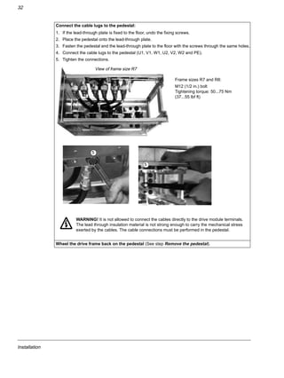
![Installation
13
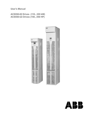
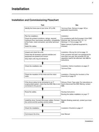
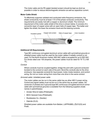
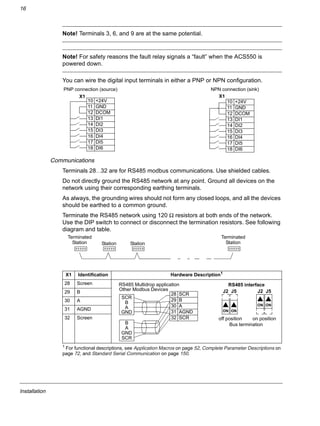
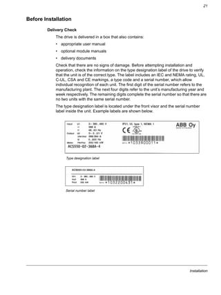
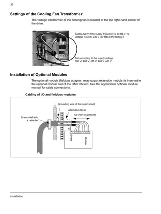
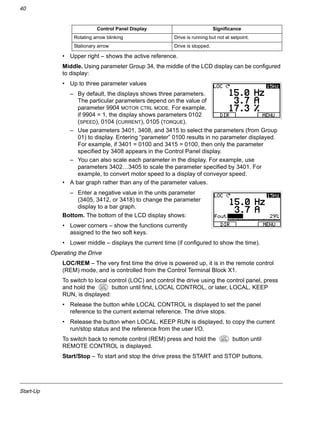
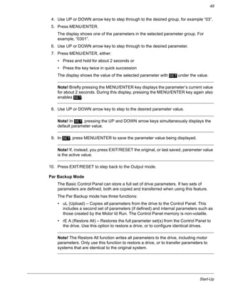
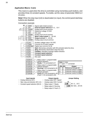
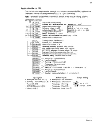
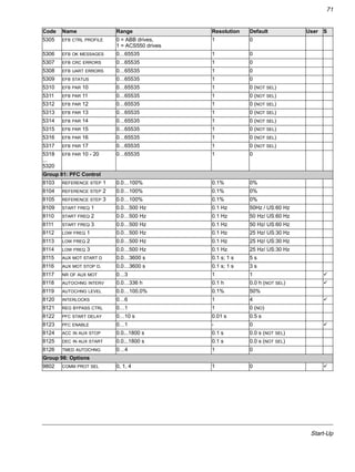
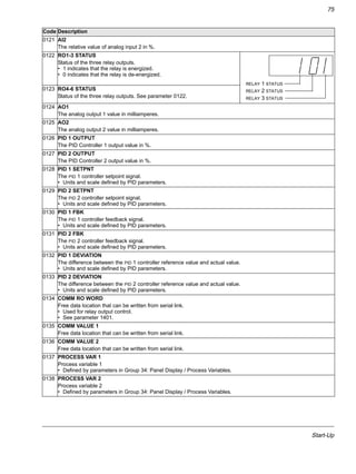
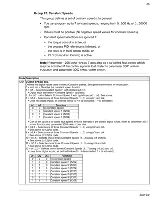
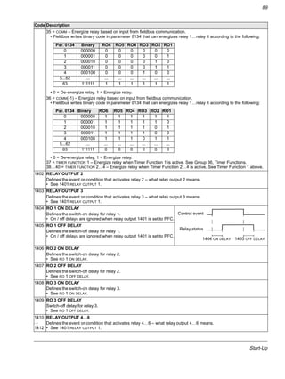
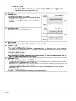
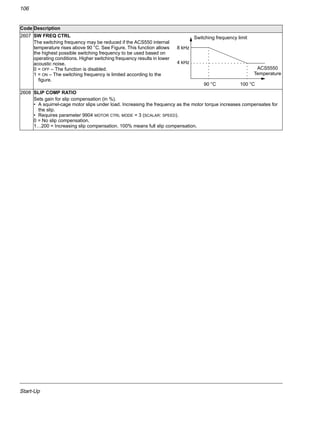
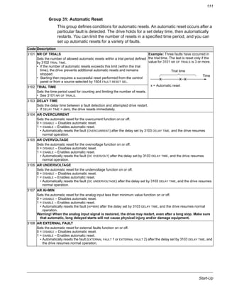
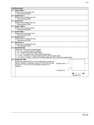
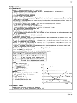
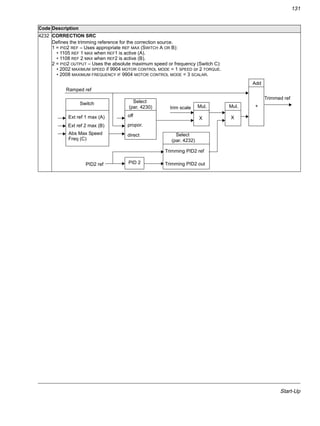
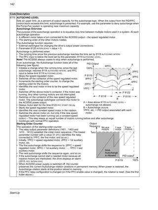
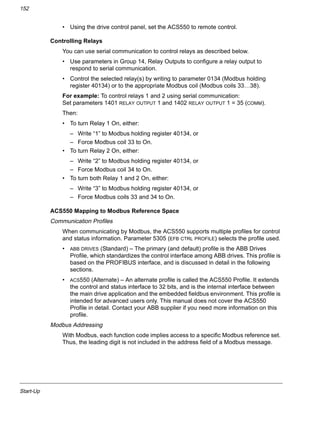
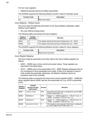
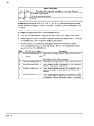
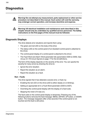
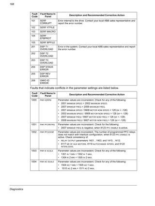
Protecting the Relay Output Contacts and Attenuating Disturbances in
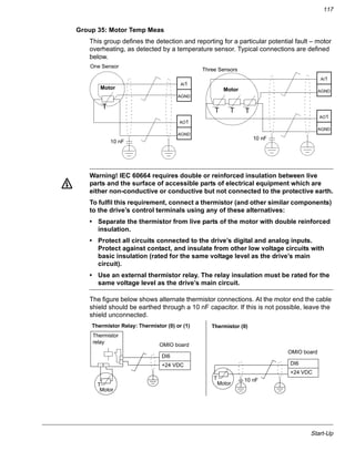
Case of Inductive Loads
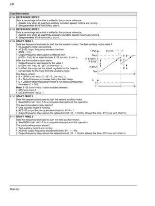
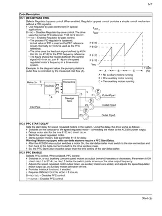
Inductive loads (relays, contactors, motors) cause voltage transients when switched
off.
It is highly recommended to equip inductive loads with noise attenuating circuits
[varistors, RC filters (AC) or diodes (DC)] in order to minimize the EMC emission at
switch-off. If not suppressed, the disturbances may connect capacitively or
inductively to other conductors in the control cable and form a risk of malfunction in
other parts of the system.
Install the protective component as close to the inductive load as possible. Do not
install protective components at the OMIO board terminal block.
24 VDC
230 VAC
19 RO1C
20 RO1A
21 RO1B
22 RO2C
23 RO2A
24 RO2B
25 RO3C
26 RO3A
27 RO3B
OMIO
230 VAC
Diode
Varistor
RC filter
Digital outputs
X1](https://image.slidesharecdn.com/acs550-02-us-04-140613212433-phpapp01/85/Acs550-02-us-04-15-320.jpg)
![Installation
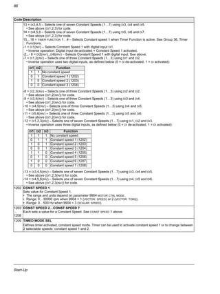
20
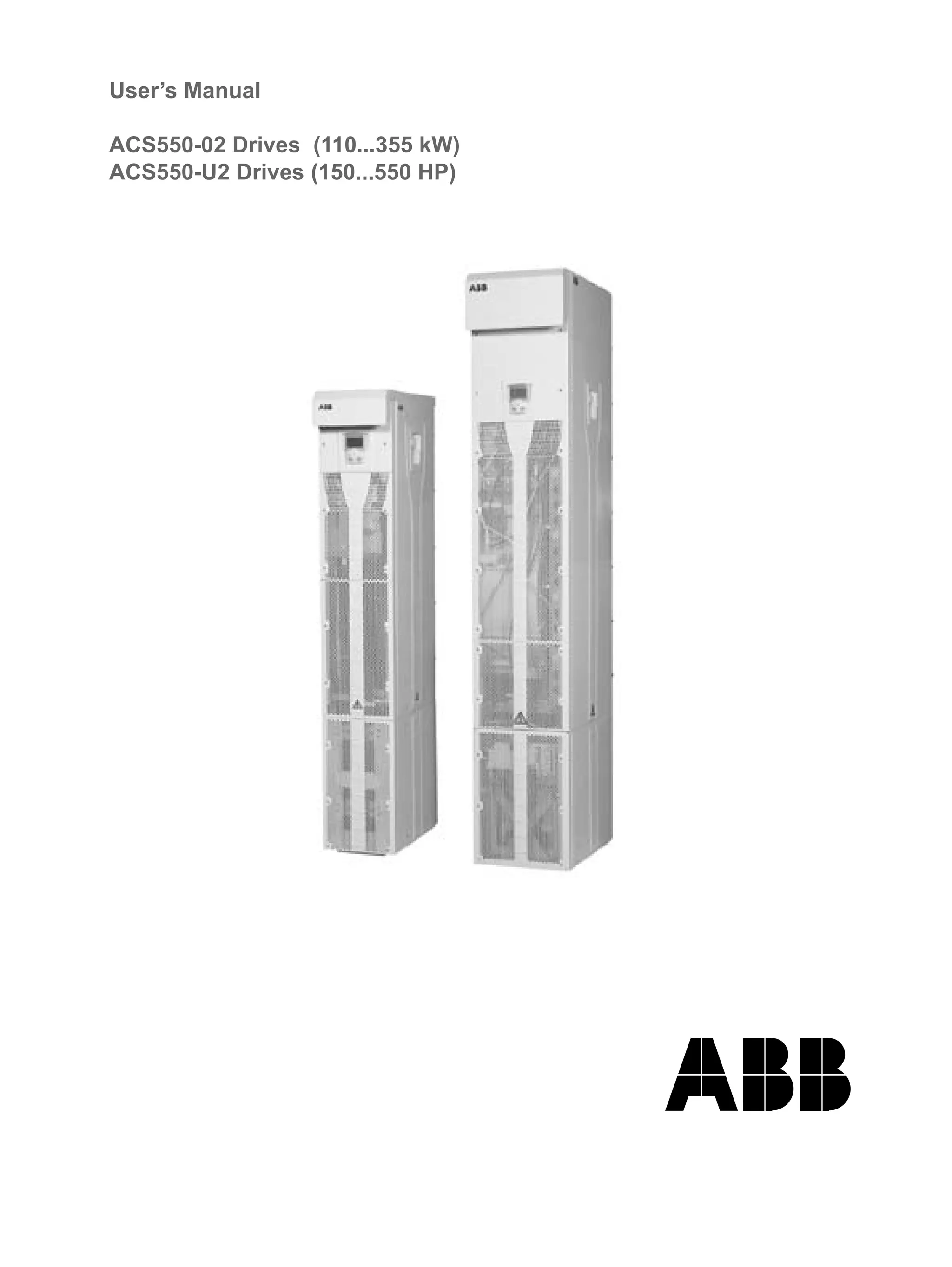
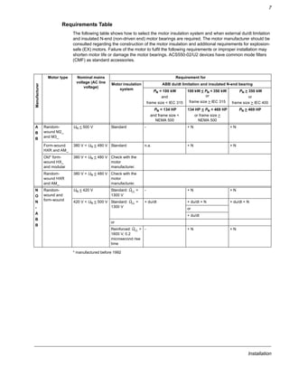
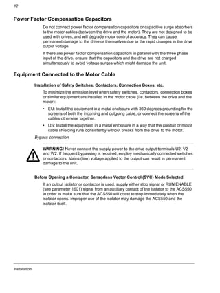
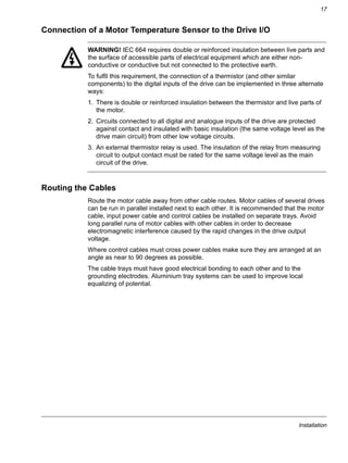
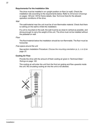
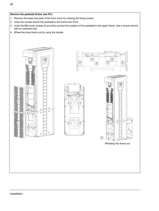
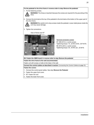
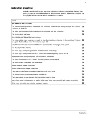
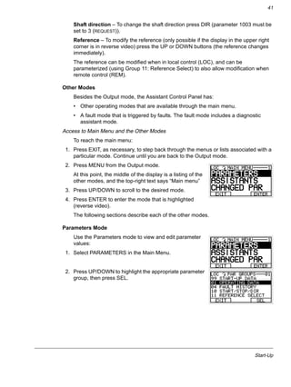
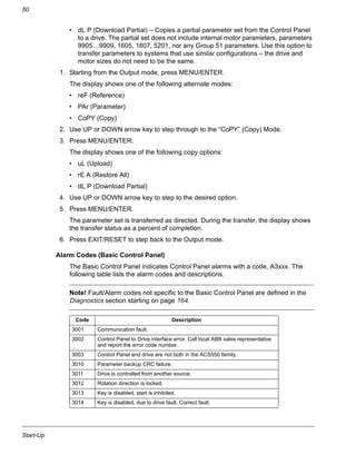
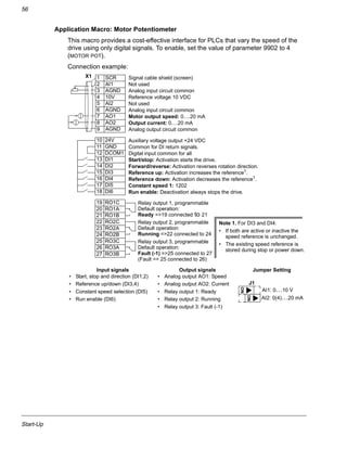
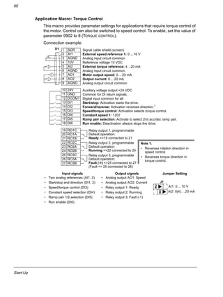
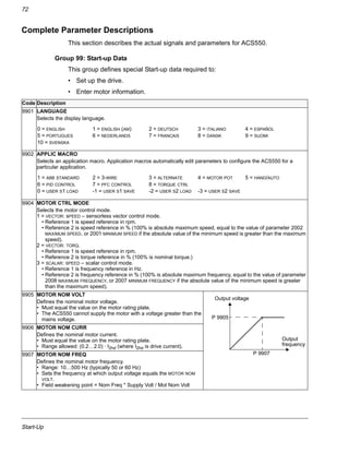
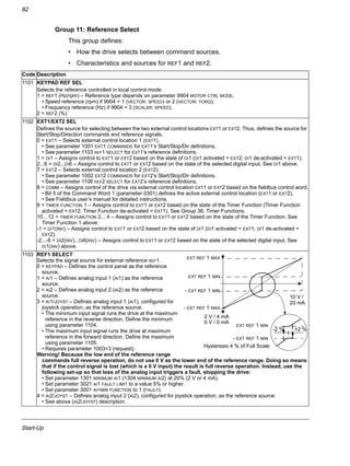
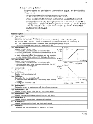
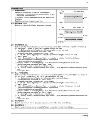
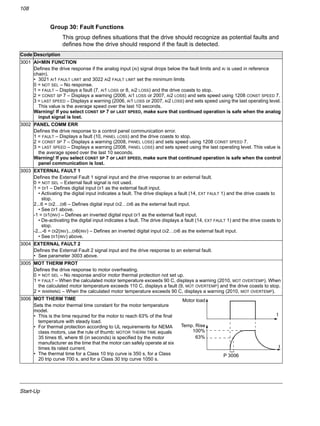
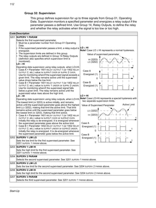
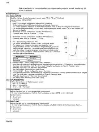
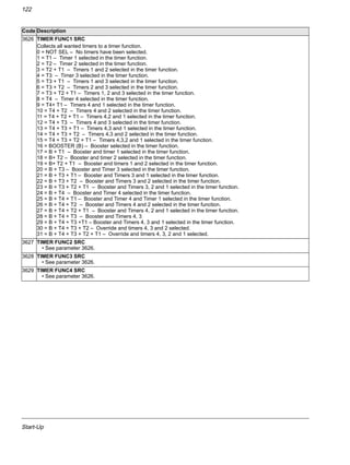
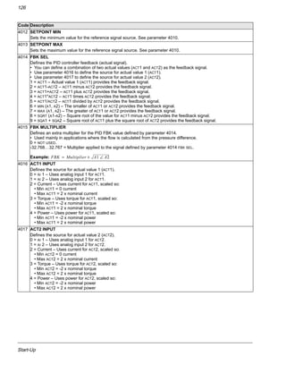
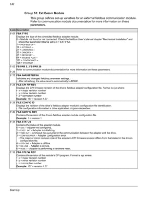
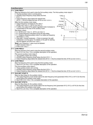
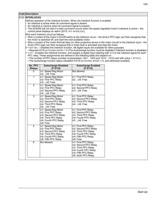
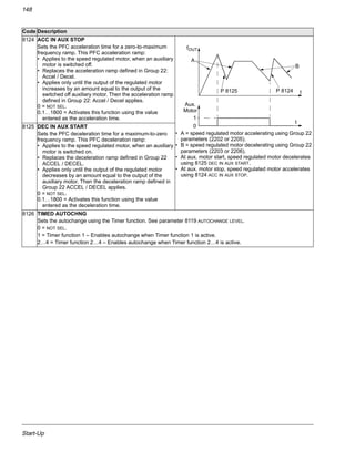
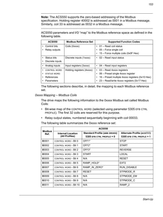
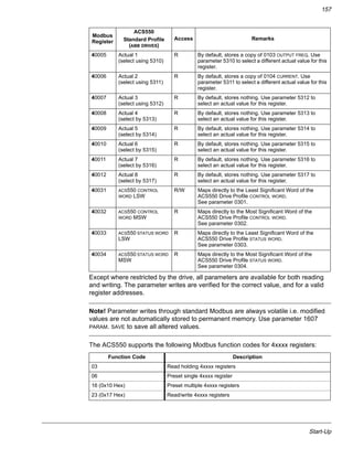
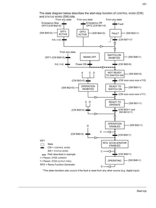
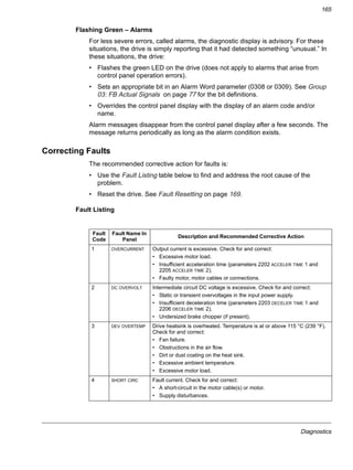
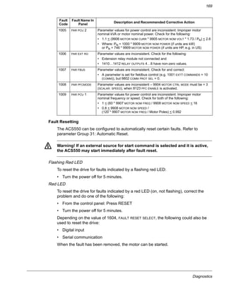
WARNING! The drive is heavy [frame size R7: 100 kg (220 lb), frame size R8:
230 kg (507 lb)]. Lift the drive by the upper part only using the lifting lugs attached to
the top of the unit. The lower part will be deformed from lifting. Do not remove the
pedestal before lifting.
Do not tilt the drive. The centre of gravity of the unit is high. The unit will overturn
from a tilt of about 6 degrees.
Do not wheel the drive except for installation (the front direction is preferable
because the front wheels are steadier). The drive frame may be deformed from
wheeling when the pedestal is removed. If the drive is moved over long distances,
place it on its back on a pallet and move it by fork-lift.
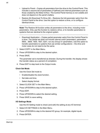
Do not lift by the lower
part of the frame.
FrontBack
Do not tilt!
Do not
wheel over long
distances.
Frame size R8:
The support legs must be locked to open
position during the installation and
always when wheeling the unit.](https://image.slidesharecdn.com/acs550-02-us-04-140613212433-phpapp01/85/Acs550-02-us-04-22-320.jpg)
![Installation
23
IT (ungrounded) Systems
The ACS550 drive is suitable for IT (ungrounded systems). Disconnect the filter
before connecting the drive to an ungrounded system. For detailed instructions on
how to do this, please contact your local ABB representative.
WARNING! If a drive is installed on an IT system [an ungrounded power system or a
high resistance-grounded (over 30 ohms) power system], the system will be
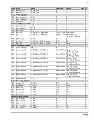
connected to earth potential through the EMC filter capacitors of the drive. This may
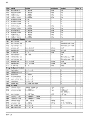
cause danger or damage the unit.
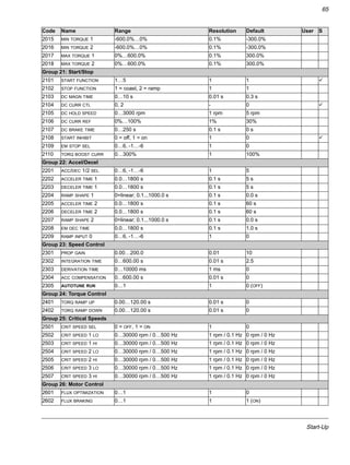
Required Tools
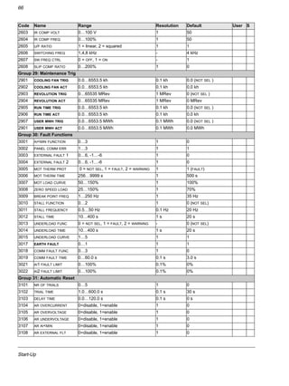
• 3 mm (0.12 in) screw driver
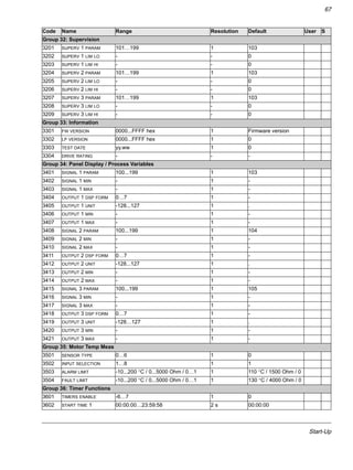
• 10 mm (3/8 in) Torx screw driver
• torque wrench with 500 mm (20 in) or 2 x 250 mm (2 x 10 in) extension bar
• 19 mm (3/4 in) socket
for frame size R7: 13 mm (1/2 in) magnetic end socket
for frame size R8: 17 mm (11/16 in) magnetic end socket.
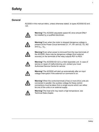
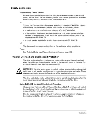
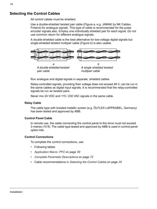
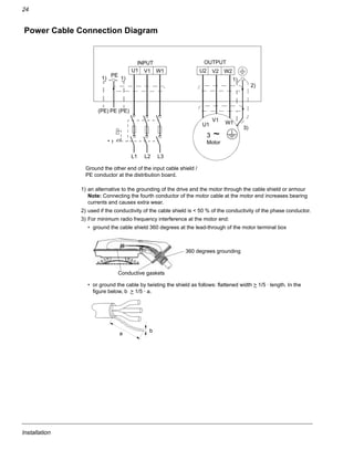
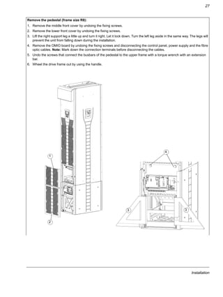
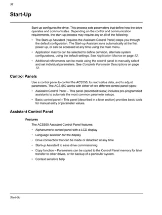
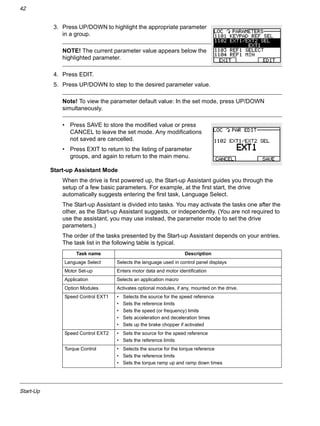
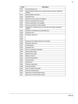
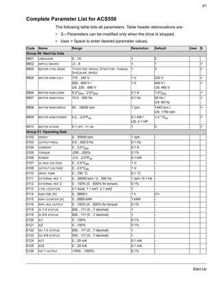
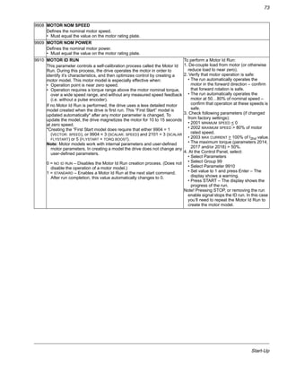
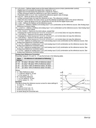
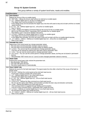
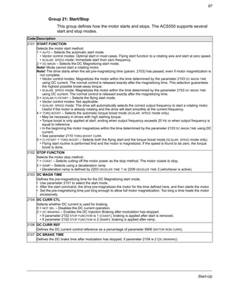
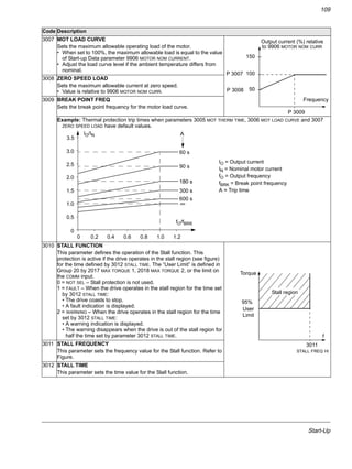
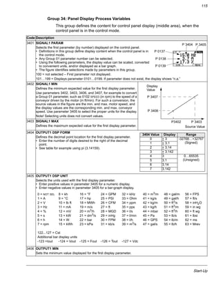
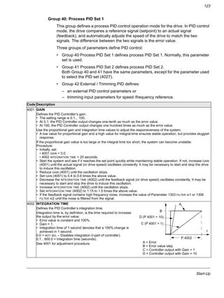
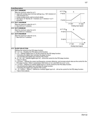
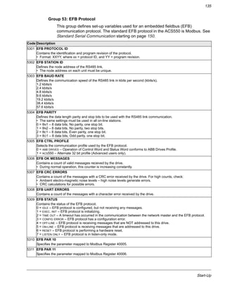
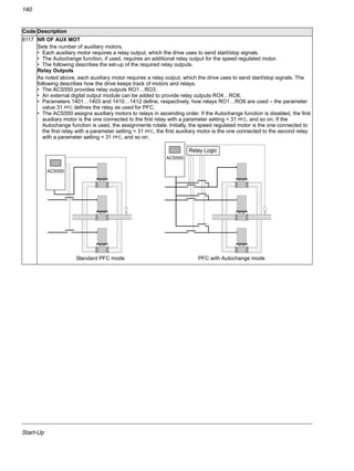
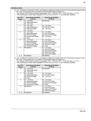
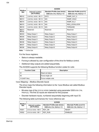
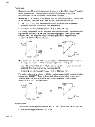
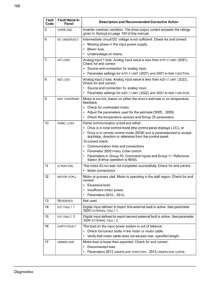
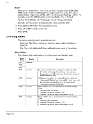
Checking the Insulation of the Assembly
Every drive has been tested for insulation between the main circuit and the chassis
(2500 V rms 50 Hz for 1 second) at the factory. Therefore, do not make any voltage
tolerance or insulation resistance tests (e.g. hi-pot or megger) on any part of the
drive. When checking the insulation of the assembly, proceed in the following
manner:
WARNING! Check the insulation before connecting the drive to the mains. Make
sure that the drive is disconnected from the mains (input power).
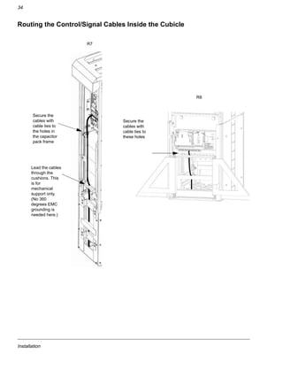
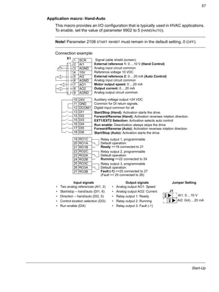
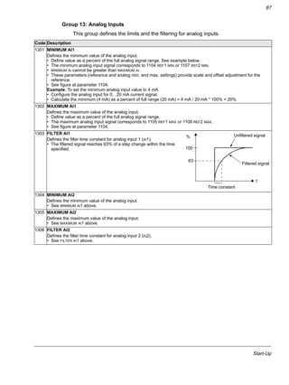
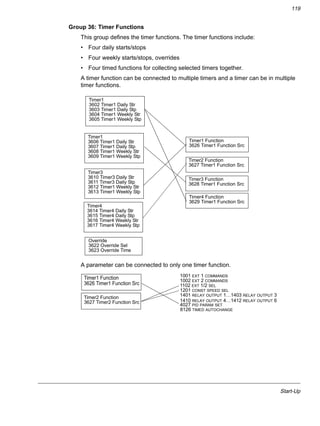
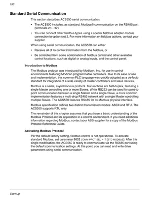
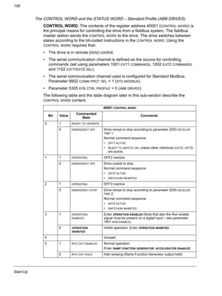
1. Check that the motor cable is disconnected from the drive output terminals U2,
V2 and W2.
2. Measure the insulation resistance of the motor cable and the motor between each
phase and the Protective Earth by using a measuring voltage of 1 kV DC. The
insulation resistance must be higher than 1 Mohm.
PE
ohm
M](https://image.slidesharecdn.com/acs550-02-us-04-140613212433-phpapp01/85/Acs550-02-us-04-25-320.jpg)
![Installation
30
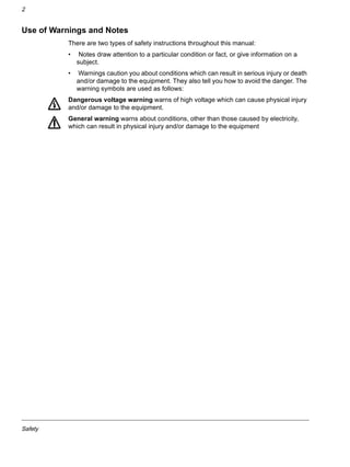
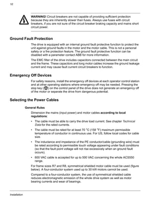
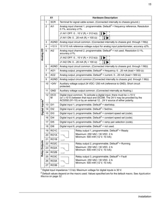
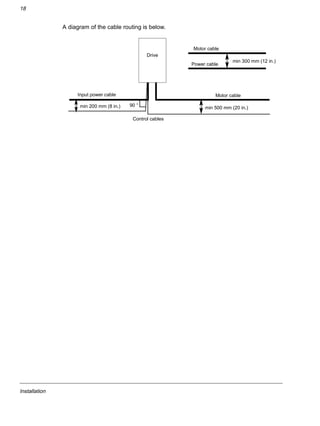
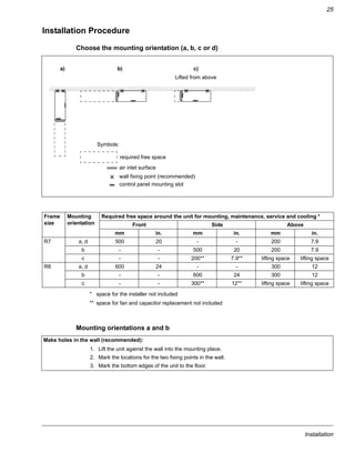
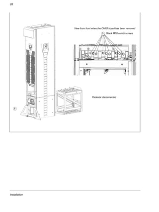
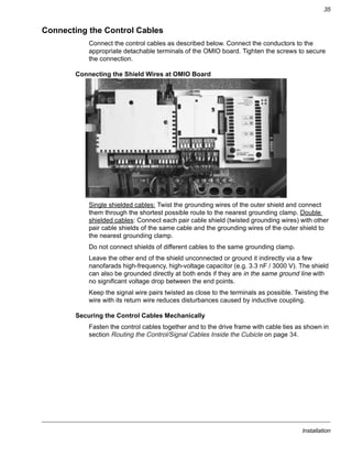
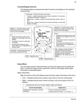
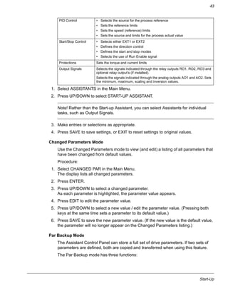
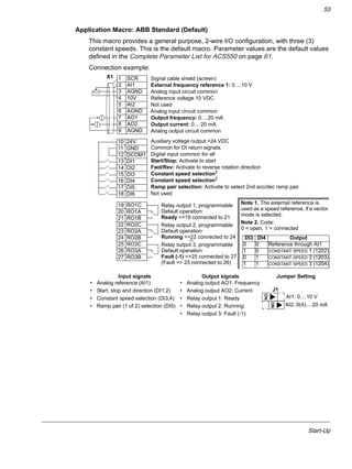
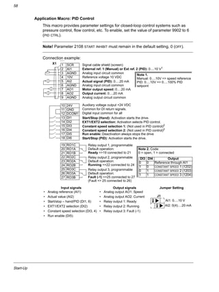
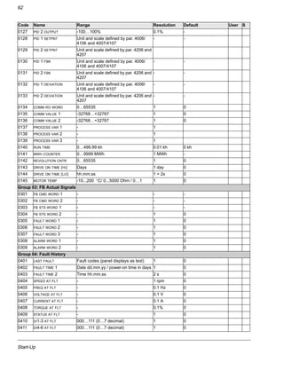
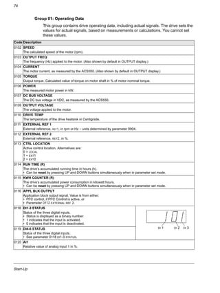
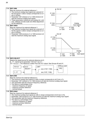
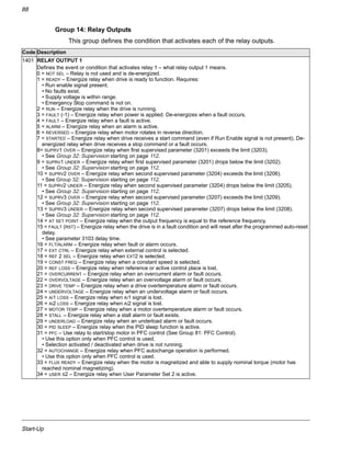
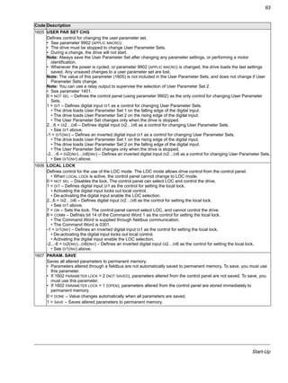
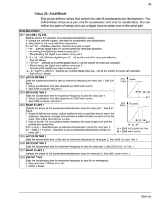
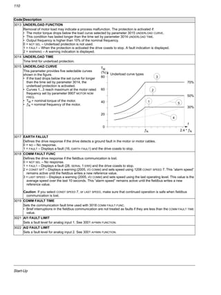
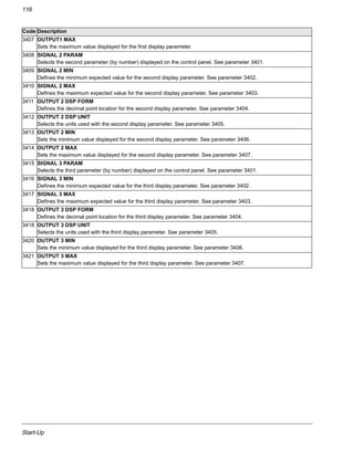
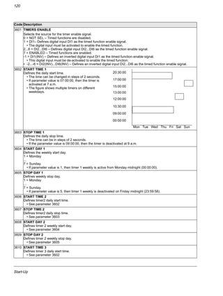
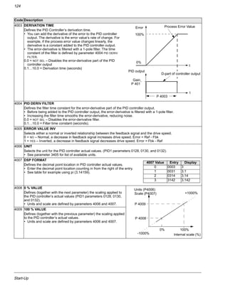
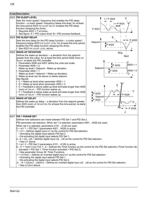
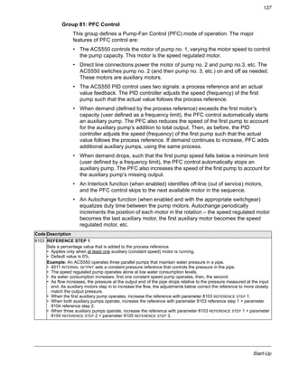
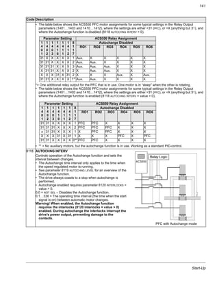
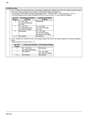
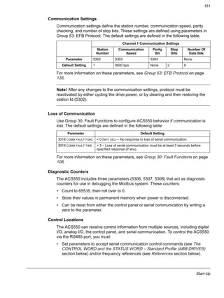
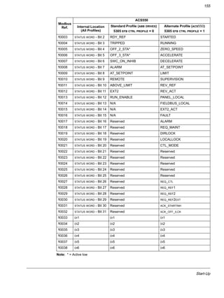
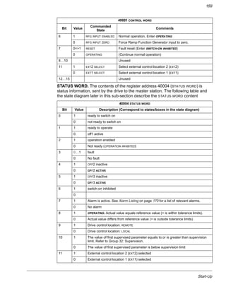
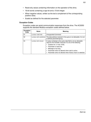
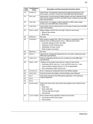
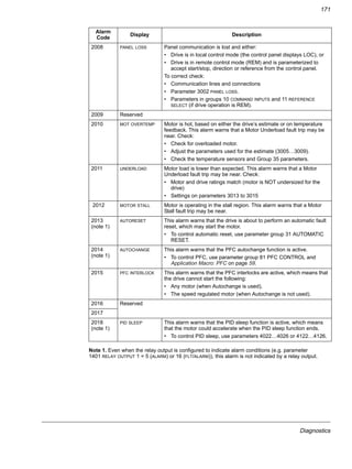
Prepare the power cables:
1. Strip the cables.
2. Twist the shield wires.
3. Bend the conductors to the terminals.
4. Cut the conductors to adequate length. Put the pedestal onto the lead-through plate and check the
length of the conductors. Remove the pedestal.
5. Press cable lugs in the conductors, or screw in connectors.
WARNING! The maximum allowed width of the cable lug is 38 mm (1.5 in.). Wider cable
lugs may cause a short-circuit.
6. Connect the twisted shields of the cables to the PE terminal (frame size R7), or to the grounding
clamps or PE terminal (frame size R8).
Note: 360 degrees grounding is not needed at the cable entry. The short twisted shield provides, in
addition to the protective grounding, also sufficient disturbance suppression.
Frame size R7
Terminal U1, U2 V1, V2 W1, W2 UDC+/UDC-
A (hole 1) / mm [in.] 159 [6.3] 262 [10.3] 365 [14.4] - 3 [0.1]
A (hole 2) / mm [in.] 115 [4.5] 218 [8.5] 321 [12.6] - -
PE terminal hole 1 2 3 4 5 6
B / mm [in.] 43 [1.7] 75 [3.0] 107 [4.2] 139 [5.5] 171 [6.7] 203 [8.0]
64582313](https://image.slidesharecdn.com/acs550-02-us-04-140613212433-phpapp01/85/Acs550-02-us-04-32-320.jpg)
![Installation
31
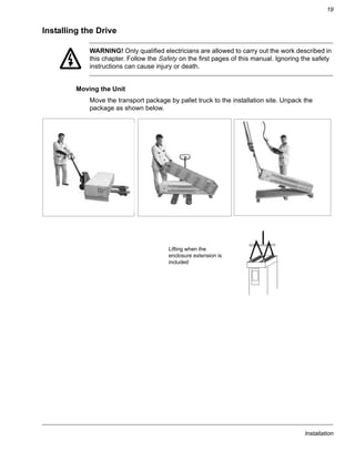
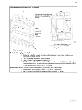
Lead the control cables through the lead-through plate:
1. Cut holes in the grommets to fit them tightly onto the control cables.
2. Lead the control cables through the lead-through plate and slide the grommets onto the cables.
Terminal A B A B
hole 1 hole 2 hole 3 hole 1 hole 2 hole 3
mm mm mm mm in. in. in. in.
Frame size R8
U1 432 387 342 40 17.0 15.2 13.5 1.6
V1 148 5.8
W1 264 10.4
U2 284 239 194 40 11.2 9.4 7.6 1.6
V2 148 5.8
W2 264 10.4
PE terminal hole 1 2 3 4 5 6 7 8 9
C / mm [in.] 24 [0.9] 56 [2.2] 88 [3.5] 120 [4.7] 152 [6.0] 184 [7.2] 216 [8.5] 248 [9.8] 280 [11.0]
Frame size R8
64605569
PE](https://image.slidesharecdn.com/acs550-02-us-04-140613212433-phpapp01/85/Acs550-02-us-04-33-320.jpg)


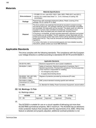
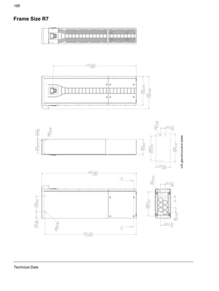
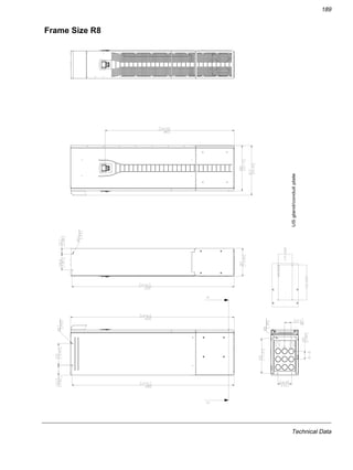
![Technical Data
187
required unless more than one motor is connected to the drive or unless additional
protection is required by applicable safety regulations. See parameters 3005 (MOT
THERM PROT) and 3006 (MOT THERM RATE).
The drives are to be used in a controlled environment. See section Ambient
Conditions on page 185 for specific limits.
Brake chopper - ABB has brake choppers that, when applied with appropriately
sized brake resistors, will allow the drive to dissipate regenerative energy (normally
associated with quickly decelerating a motor).
Dimension Drawings
The dimensions are given in millimetres and [inches].](https://image.slidesharecdn.com/acs550-02-us-04-140613212433-phpapp01/85/Acs550-02-us-04-189-320.jpg)


This document provides manuals for ACS550 adjustable speed AC drives including safety, installation, start-up, diagnostics, and maintenance information. It contains details on preparing for installation such as checking motor compatibility, protecting the motor winding and bearings, routing cables, installing the drive, and checking the installation. Technical specifications and drawings are also included to aid in the selection and installation of the appropriate drive model.


![Ct2000 pro plus_manual_english[1]](https://cdn.slidesharecdn.com/ss_thumbnails/ct2000proplusmanualenglish1-140613213527-phpapp02-thumbnail.jpg?width=640&height=640&fit=bounds)


![Ct2000 es manual_english_version_1[1].0](https://cdn.slidesharecdn.com/ss_thumbnails/ct2000esmanualenglishversion11-140613213448-phpapp01-thumbnail.jpg?width=640&height=640&fit=bounds)


