Download to read offline
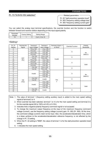
![A - 3
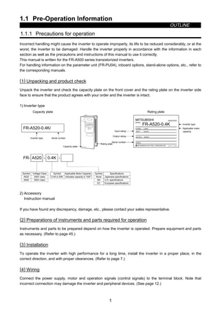
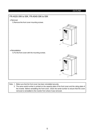
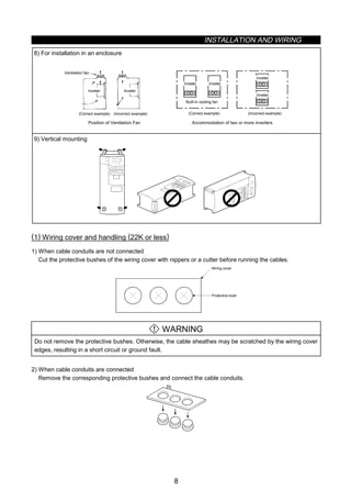
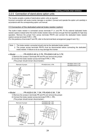
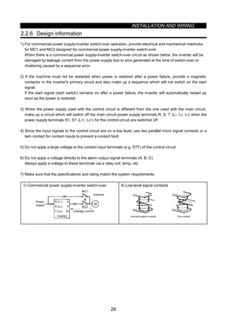
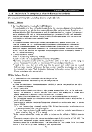
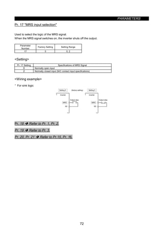
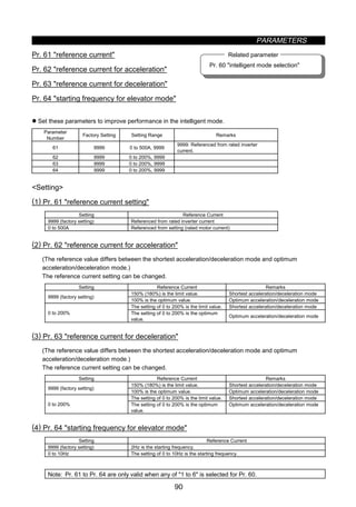
4. Additional instructions
Also note the following points to prevent an accidental failure, injury, electric shock, etc.:
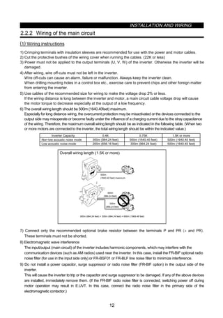
(1) Transportation and installation
CAUTION
z When carrying products, use correct lifting gear to prevent injury.
z Do not stack the inverter boxes higher than the number recommended.
z Ensure that installation position and material can withstand the weight of the inverter. Install
according to the information in the Instruction Manual.
z Do not operate if the inverter is damaged or has parts missing.
z Do not hold the inverter by the front cover; it may fall off.
z Do not stand or rest heavy objects on the inverter.
z Check the inverter mounting orientation is correct.
z Prevent screws, wire fragments, conductive bodies, oil or other flammable substances from entering
the inverter.
z Do not drop the inverter, or subject it to impact.
z Use the inverter under the following environmental conditions:
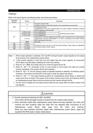
Ambient temperature
Constant torque: -10°C to +50°C (14°F to 122°F) (non-freezing)
(-10°C to +40°C with FR-A5CVUU attachment)
Variable torque: -10°C to +40°C (14°F to 104°F) (non-freezing)
(-10°C to +30°C with FR-A5CVUU attachment)
Ambient humidity 90%RH or less (non-condensing)
Storage temperature -20°C to +65°C* (-4°F to 149°F)
Ambience Indoors (free from corrosive gas, flammable gas, oil mist, dust and dirt)
Environment
Altitude, vibration
Maximum 1000m (3280.80 feet.) above sea level for standard operation.
After that derate by 3% for every extra 500m up to 2500m (91%).
••*Temperatures applicable for a short time, e.g. in transit.
(2) Wiring
CAUTION
z Do not fit capacitive equipment such as a power factor correction capacitor, noise filter or surge
suppressor to the output of the inverter.
z The connection orientation of the output cables U, V, W to the motor will affect the direction of
rotation of the motor.
(3) Trial run
CAUTION
z Check all parameters, and ensure that the machine will not be damaged by a sudden start-up.
(4) Operation
CAUTION
z When you have chosen the retry function, stay away from the equipment as it will restart suddenly
after an alarm stop.
z The [STOP] key is valid only when the appropriate function setting has been made. Prepare an
emergency stop switch separately.
z Make sure that the start signal is off before resetting the inverter alarm. A failure to do so may restart
the motor suddenly.](https://image.slidesharecdn.com/fr-a500-140613032347-phpapp01/85/Fr-a500-4-320.jpg)
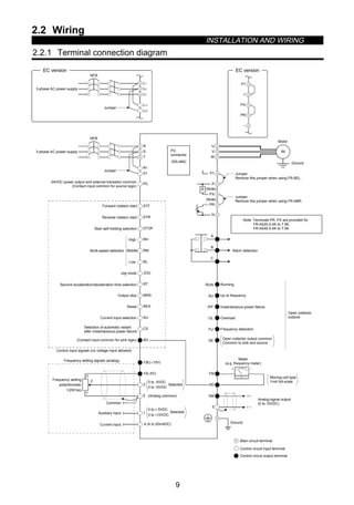
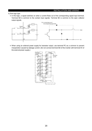
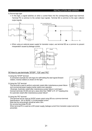
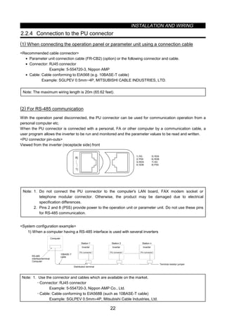
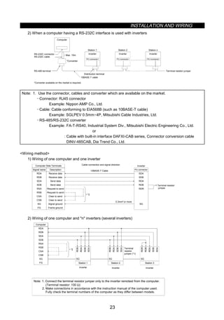
![INSTALLATION AND WIRING
31
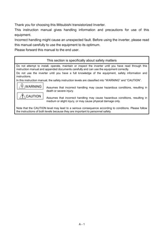
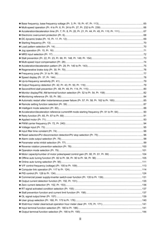
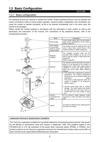
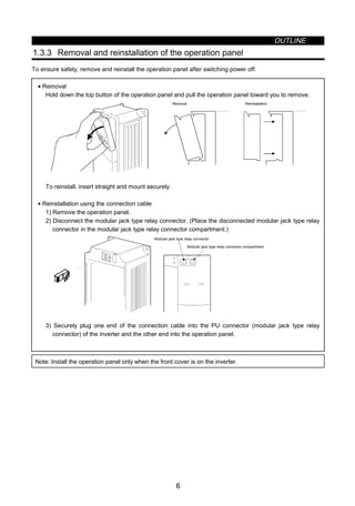
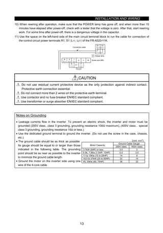
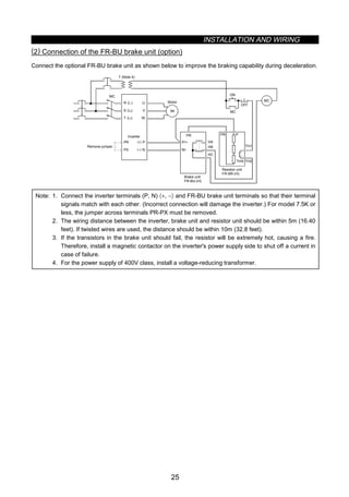
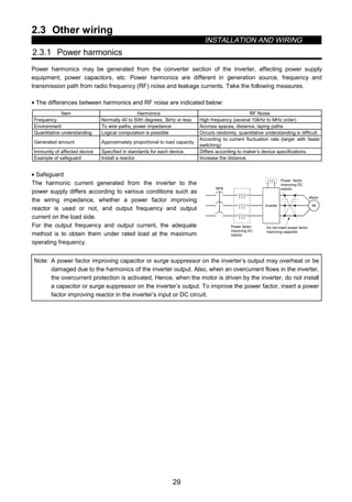
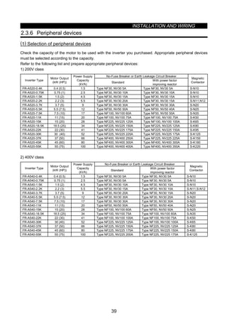
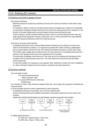
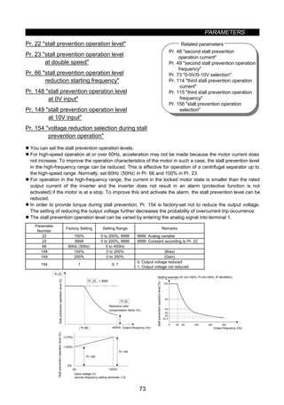
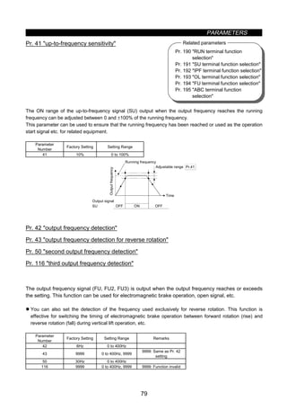
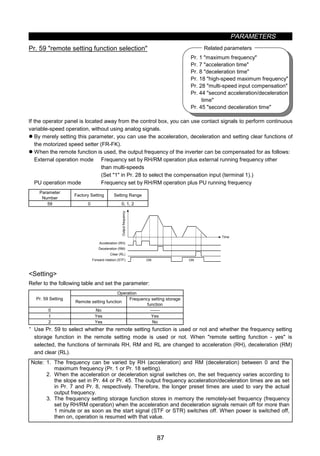
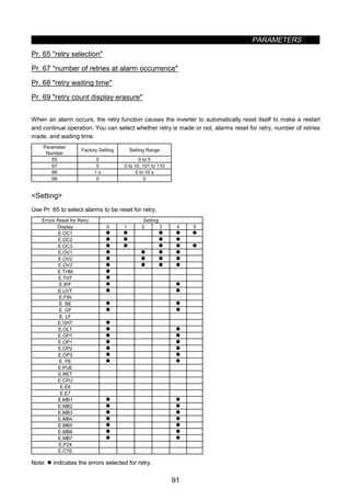
Table 3 Equivalent Capacity Limits
Received Power Voltage Reference Capacity
6.6kV 50kVA
22/33kV 300kVA
66kV or more 2000kVA
Table 4 Harmonic Content (Values at the fundamental current of 100%)
Reactor 5th 7th 11th 13th 17th 19th 23rd 25th
Not used 65 41 8.5 7.7 4.3 3.1 2.6 1.8
Used (AC side) 38 14.5 7.4 3.4 3.2 1.9 1.7 1.3
Used (DC side) 30 13 8.4 5.0 4.7 3.2 3.0 2.2
Used (AC, DC sides) 28 9.1 7.2 4.1 3.2 2.4 1.6 1.4
1) Calculation of equivalent capacity (P0) of harmonic generating equipment
The “equivalent capacity” is the capacity of a 6-pulse converter converted from the capacity of consumer’s
harmonic generating equipment and is calculated with the following equation. If the sum of equivalent
capacities is higher than the limit in Table 3, harmonics must be calculated with the following procedure:
P0 = Σ (Ki × Pi) [kVA]
Ki: Conversion factor (refer to Table 2)
Pi: Rated capacity of harmonic generating equipment* [kVA]
I : Number indicating the conversion circuit type
*: Rated capacity: Determined by the capacity
of the applied motor and found in Table 5. It
should be noted that the rated capacity
used here is used to calculate generated
harmonic amount and is different from the
power supply capacity required for actual
inverter drive.
2) Calculation of outgoing harmonic current
Outgoing harmonic current = fundamental wave current (value converted from received power voltage) ×
operation ratio × harmonic content
• Operation ratio: Operation ratio = actual load factor × operation time ratio during 30 minutes
• Harmonic content: Found in Table 4.
Table 5 Rated Capacities and Outgoing Harmonic Currents for Inverter Drive
Rated Current [A]
Fundamental
Wave Current
Converted from
6.6kV
Rated
Capacity
Fundamental Wave Current Converted from 6.6kV
(No reactor, 100% operation ratio)
Applied
Motor
(kW (HP))
200V 400V (mA) (kVA) 5th 7th 11th 13th 17th 19th 23rd 25th
0.4 (0.5) 0.81 49 0.57 31.85 20.09 4.165 3.773 2.107 1.519 1.274 0.882
0.75 (1) 1.37 83 0.97 53.95 34.03 7.055 6.391 3.569 2.573 2.158 1.494
1.5 (2) 2.75 167 1.95 108.6 68.47 14.20 12.86 7.181 5.177 4.342 3.006
2.2 (3) 3.96 240 2.81 156.0 98.40 20.40 18.48 10.32 7.440 6.240 4.320
3.7 (5)
Not
applied
6.50 394 4.61 257.1 161.5 33.49 30.34 16.94 12.21 10.24 7.092
5.5 (7.5) 19.1 9.55 579 6.77 376.1 237.4 49.22 44.58 24.90 17.95 15.05 10.42
7.5 (10) 25.6 12.8 776 9.07 504.4 318.2 65.96 59.75 33.37 24.06 20.18 13.97
11 (15) 36.9 18.5 1121 13.1 728.7 459.6 95.29 86.32 48.20 34.75 29.15 20.18
15 (20) 49.8 24.9 1509 17.6 980.9 618.7 128.3 116.2 64.89 46.78 39.24 27.16
18.5 (25) 61.4 30.7 1860 21.8 1209 762.6 158.1 143.2 79.98 57.66 48.36 33.48
22 (30) 73.1 36.6 2220 25.9 1443 910.2 188.7 170.9 95.46 68.82 57.72 39.96
30 (40) 98.0 49.0 2970 34.7 1931 1218 252.5 228.7 127.7 92.07 77.22 53.46
37 (50) 121 60.4 3660 42.8 2379 1501 311.1 281.8 157.4 113.5 95.16 65.88
45 (60) 147 73.5 4450 52.1 2893 1825 378.3 342.7 191.4 138.0 115.7 80.10
55 (75) 180 89.9 5450 63.7 3543 2235 463.3 419.7 234.4 169.0 141.7 98.10
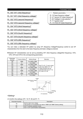
3) Harmonic suppression technique requirement
If the outgoing harmonic current is higher than; maximum value per 1kW (contract power) × contract
power, a harmonic suppression technique is required.](https://image.slidesharecdn.com/fr-a500-140613032347-phpapp01/85/Fr-a500-41-320.jpg)
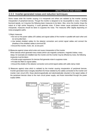
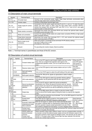
![INSTALLATION AND WIRING
35
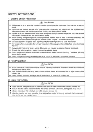
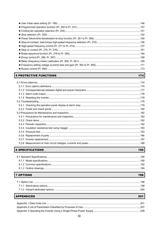
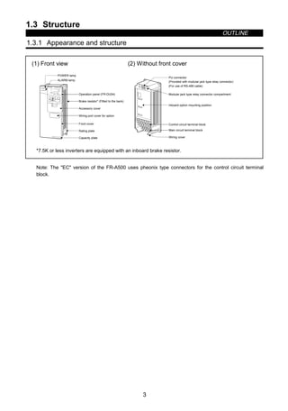
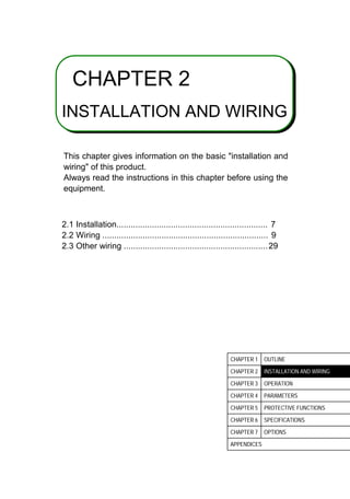
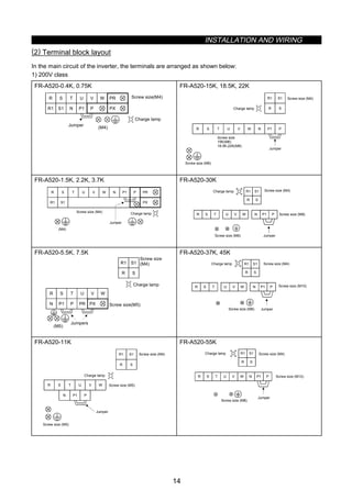
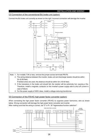
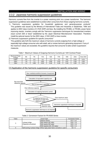
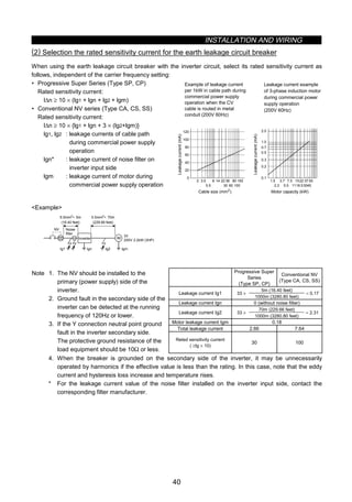
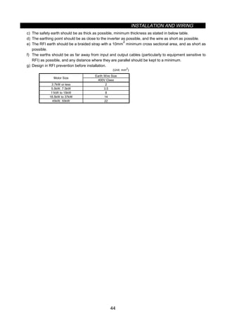
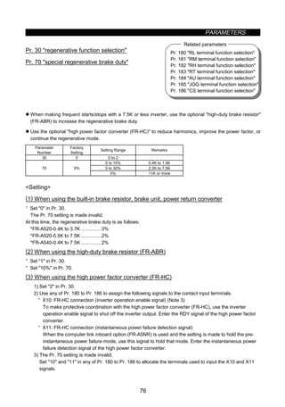
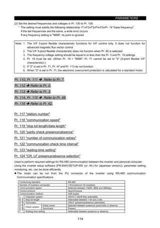
• Data line filter
Noise entry can be prevented by providing a data line filter for the detector cable etc.
Example Data line filter: ZCAT3035-1330 (TDK make)
ESD-SR-25 (Tokin make)
Impedance specifications (ZCAT3035-1330)
Impedance (Ω)
10 to 100MHz 100 to 500MHz
80 150
The above impedance values are reference values
and not guaranteed values.
34±1
TDK
39±1
Product name Lot number
φ30±1
Cable fixing band
mounting section
φ13±1
Outline Dimension Drawing (ZCAT3035-1330)
[Unit : mm]
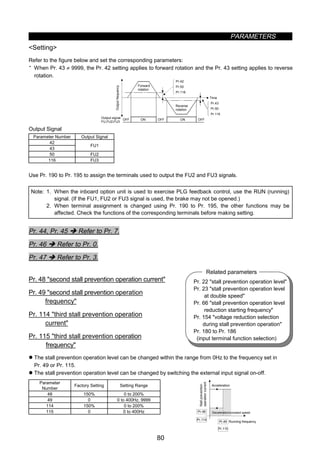
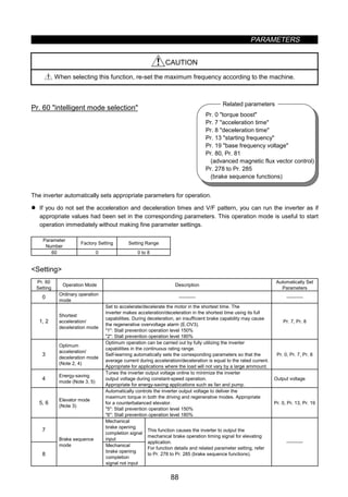
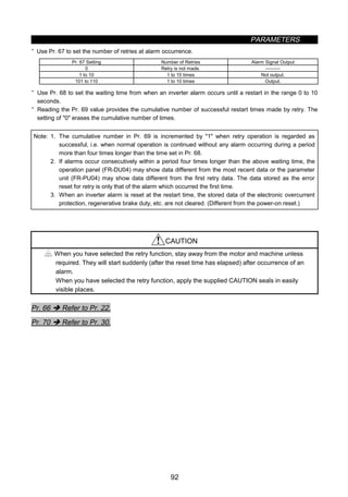
• Data examples
By decreasing the carrier frequency, the noise terminal voltage*
can be reduced. Use Pr. 72 to set the carrier frequency to a low
value (1kHz).
Though motor noise increases at a low carrier frequency,
selection of Soft-PWM in Pr. 240 will make it unoffending.
Differences between Noise Terminal Voltages
at Different Carrier Frequencies
0.1 0.3 0.5 1 3 5 10 30
20
60
80
100
120
0
FR-A520-3.7K
fc=0.7kHz
fc=14.5kHz
fc=2.0kHz Soft-PWM(Factory setting)
FR-A220E-3.7k fc=(14.5kHz)
Conditions
‚ Motor: 3.7kW (5HP)
‚ Average terminal voltage 0dB=1µV
120dB=1V
Noiseterminalvoltage(dB)
Noise frequency (MHz)
By decreasing the carrier frequency, noise will be about as low
as that of our conventional FR-Z200 series.
By using shielded cables as signal cables, induction noise can
be reduced greatly (to 1/10 - 1/100). Induction noise can also be
reduced by moving the signal cables away from the inverter
output cables. (Separation of 30cm (11.81 inches) reduces noise
to 1/2-1/3.)
By fitting the FR-BSF01 or BLF on the inverter output side,
induction noise to the signal cables can be reduced.
Noise Terminal Voltage of Inverter and Example
of Its Reduction by Noise ilters
0.1 0.3 0.5 1 3 5 10 30
20
60
80
100
120
0
FR-A520-3.7k(fc=0.7kHz)
FR-Z220-3.7K
Noise frequency (MHz)
Noiseterminalvoltage(dB)
Conditions
‚ Motor:3.7kW (5HP)
‚ Average terminal voltage 0dB=1µV
120dB=1V
Noise Induced to Signal Cables by Inverter Output Cables
20
40
60
80
100
100 20 30 40 50
5cm
d(cm)
FR-BLF
FR-BSF01
(4T)
Line-to-line distance, d (cm)
Inductionvoltage(dB)
Parallel cable
Twisted pair cable
Coaxial cable
Conditions
‚ Inverter: FR-A520-3.7K
‚ Motor: FR-JR 4P 3.7kW (5HP)
‚ Output frequency: 30Hz
‚ Noise form: Normal mode
Inverter Motor
Terminal
Measuring instrument
*Noise terminal voltage: Represents the magnitude of noise propagated from the inverter to the power supply.](https://image.slidesharecdn.com/fr-a500-140613032347-phpapp01/85/Fr-a500-45-320.jpg)
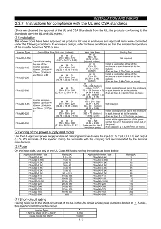
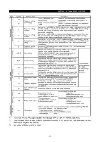
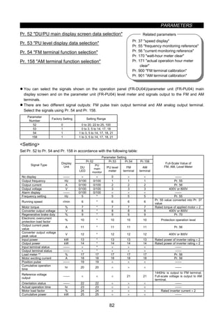
![OPERATION
46
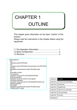
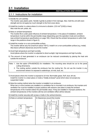
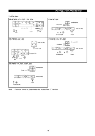
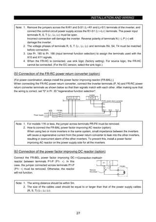
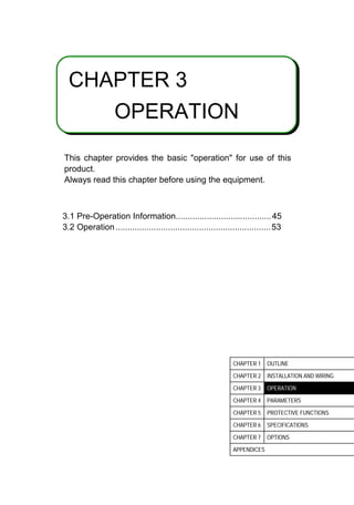
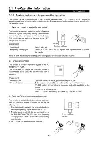
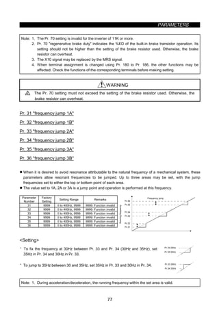
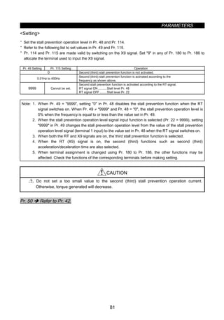
Preparation
· Start signal ..................................Switch, relay, etc. (for 1)
· Frequency setting signal .............0 to 5V, 0 to 10V, 4 to 20mA DC signals from a potentiometer or outside
the inverter (for 2)
· Operation unit..............................Operation panel (FR-DU04), parameter unit (FR-PU04)
· Connection cable ........................To be prepared for use of the operation unit away from the inverter
FR-CB2 (option) or the following connector and cable available on the
market:
Connector : RJ45 connector
Cable : Cable conforming to EIA568 (e.g. 10BASE-T cable)
3) Combined operation mode
Change the setting of Pr. 79 operation mode selection as follows:
Description
Setting
Running frequency setting Start signal
3
PU (FR-DU04/FR-PU04)
· Direct setting and [UP/DOWN] key setting
Terminal signal
· STF
· STR
4
Terminal signal
·0 to 5VDC across 2-5
·0 to 10VDC across 2-5
·4 to 20mADC across 4-5
·Multi-speed selection (Pr. 4 to Pr. 6, Pr. 24
to Pr. 27, Pr. 232 to Pr. 239)
·Jog frequency (Pr. 15)
Parameter unit
· [FWD] key
· [REV] key
(4) Communication operation mode
Communication operation can be performed by connecting a personal computer and the PU connector with
the RS-485 communication cable.
The inverter setup software is available as an FR-A500 inverter start-up support software package.
Preparation
· Connection cable ........................Connector : RJ45 connector
Cable : Cable conforming to EIA568
(e.g. 10BASE-T cable)
· Personal computer
Inverter setup software operating environment
OS ................................................Windows 3.1, Windows 95
RAM..............................................1MB or more
Floppy disk drive...........................One or more 3.5 inch floppy
disk drives
Mouse...........................................Mouse connectable to the
personal computer](https://image.slidesharecdn.com/fr-a500-140613032347-phpapp01/85/Fr-a500-57-320.jpg)
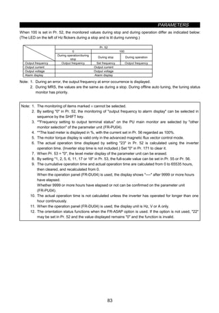
![OPERATION
47
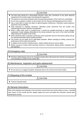
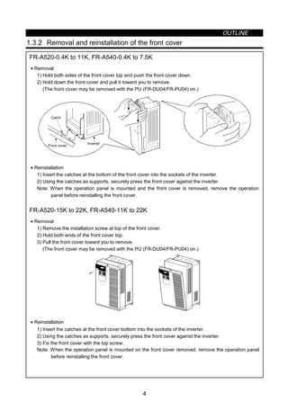
3.1.2 Power on
Before switching power on, check the following:
• Installation check
Make sure that the inverter is installed correctly in a correct place. (Refer to page 7.)
· Wiring check
Make sure that the main and control circuits are wired correctly.
Make sure that the options and peripheral devices are selected and connected correctly.
(Refer to page 9.)
• Switch power on.
Power-on is complete when the POWER lamp is lit correctly and the operation panel (FR-DU04) displays
correct data.
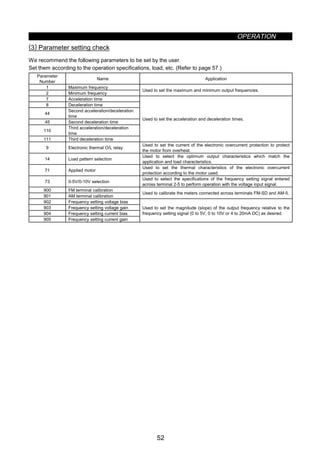
3.1.3 Parameter check
The inverter is designed to perform simple variable-speed operation with the factory settings of the
parameters. Set the necessary parameters according to the load and operation specifications. Use the
operation panel (FR-DU04) to set, change and confirm the parameter values. For full information on the
parameters, refer to CHAPTER 4 PARAMETERS (page 57).
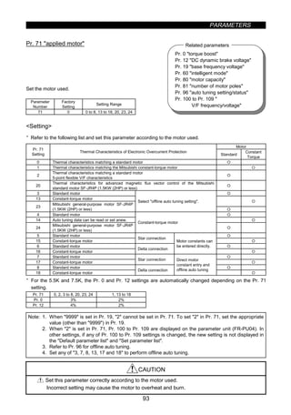
(1) Operation panel (FR-DU04)
With the operation panel (FR-DU04), you can set the running frequency, monitor the operation command
display, set parameters, display an error, and copy parameters.
1) Names and functions of the operation panel (FR-DU04)
Display
LED ×4 digits
[MODE] key
[SET] key
Unit indication
‚ Hz (frequency)
‚ A (current)
‚ V (voltage)
Operation status indication
[Operation command] keys
‚ [REV] (reverse rotation) key
‚ [FWD] (forward rotation) key
[STOP/RESET] key
FR-DU04
Hz
A
V
MON EXT PU
CONTROL PANEL
FWD
MODE
SET
REV FWD
STOP
RESET
REV
Key Description
[MODE] key You can select the operation mode or setting mode.
[SET] key You can determine the frequency and parameter setting.
[UP/DOWN] key
( key)
· Used to increase or decrease the running frequency consecutively. Hold down this key to change the
frequency.
· Press this key in the setting mode to change the parameter setting consecutively.
[REV] key Used to give a reverse rotation command.
[FWD] key Used to give a forward rotation command.
[STOP/RESET] key
· Used to stop operation.
· Used to reset the inverter when its output is stopped by the protective function activated (major fault).](https://image.slidesharecdn.com/fr-a500-140613032347-phpapp01/85/Fr-a500-58-320.jpg)
![OPERATION
48
2) Monitor display changed by pressing the [MODE] key
MODE MODE MODE MODE
MODE
zHelp modezMonitoring mode zParameter setting mode zOperation mode
FR-DU04 CONTROL PANEL
Hz
MON EXT PU
A
V
REV FWD
zFrequency setting mode (Note)
FR-DU04 CONTROL PANEL
Hz
MON EXT PU
A
V
REV FWD
FR-DU04 CONTROL PANEL
Hz
MON EXT PU
A
V
REV FWD
FR-DU04 CONTROL PANEL
Hz
MON EXT PU
A
V
REV FWD
FR-DU04 CONTROL PANEL
Hz
MON EXT PU
A
V
REV FWD
Note: The frequency setting mode is displayed only in the PU operation mode.
(2) Key operation
1) Monitoring mode
· Operation command indications in the monitoring mode
EXT is lit to indicate external operation.
PU is lit to indicate PU operation.
Both EXT and PU are lit to indicate PU/external combined operation mode.
· The monitor display can also be changed during operation.
MODE
SET SET SET
SET
SETSET
*1
SET
*1
SET
*1
*2
To 2) Frequency setting mode (Note 3)
zFrequency monitor zCurrent monitor zVoltage monitor zAlarm monitor
Alarm present
Alarm absent
FR-DU04 CONTROL PANEL
Hz
MON EXT PU
A
V
REV FWD
FR-DU04 CONTROL PANEL
Hz
MON EXT PU
A
V
REV FWD
FR-DU04 CONTROL PANEL
Hz
MON EXT PU
A
V
REV FWD
FR-DU04 CONTROL PANEL
Hz
MON EXT PU
A
V
REV FWD
Note: 1. Hold down the [SET] key marked *1 for more than 1.5 seconds to change the current monitor to
the power-on monitor.
2. Hold down the [SET] key marked *2 for more than 1.5 seconds to display four errors including the
most recent one.
3. Shifts to the parameter setting mode when in the external operation mode.
2) Frequency setting mode
· Used to set the running frequency in the PU operation mode.
MODE
SET
MODE
To 3) Parameter setting mode
zSet frequency writezSet frequency change
Press to change the set frequency.
To frequency monitor
FR-DU04 CONTROL PANEL
Hz
MON EXT PU
A
V
REV FWD
FR-DU04 CONTROL PANEL
Hz
MON EXT PU
A
V
REV FWD
FR-DU04 CONTROL PANEL
Hz
MON EXT PU
A
V
REV FWD](https://image.slidesharecdn.com/fr-a500-140613032347-phpapp01/85/Fr-a500-59-320.jpg)
![OPERATION
49
3) Parameter setting mode
· A parameter value may either be set by updating its parameter number or setting the value digit-by-digit
using the [UP/DOWN] key.
· To write the setting, change it and press the [SET] key 1.5 seconds.
Set 0 or 4 (factory setting) in Pr. 79 operation mode selection or select the PU operation mode.
MODE SET
SET SET
SET SET
MODE
SET
0 ∼ 9 0 ∼ 9 0 ∼ 9
SET
To 4) Operation mode
zParameter number change zSetting change
Press for
1.5 sec.
zSetting write
Flicker
Press
to change the setting.
Simultaneous input
Most significant digit flickers Middle digit flickers Least significant digit flickers
zhanging the parameter number
to change the parameter number.
Press
FR-DU04 CONTROL PANEL
Hz
MON EXT PU
A
V
REV FWD
FR-DU04 CONTROL PANEL
Hz
MON EXT PU
A
V
REV FWD
FR-DU04 CONTROL PANEL
Hz
MON EXT PU
A
V
REV FWD
FR-DU04 CONTROL PANEL
Hz
MON EXT PU
A
V
REV FWD
FR-DU04 CONTROL PANEL
Hz
MON EXT PU
A
V
REV FWD
FR-DU04 CONTROL PANEL
Hz
MON EXT PU
A
V
REV FWD
FR-DU04 CONTROL PANEL
Hz
MON EXT PU
A
V
REV FWD
FR-DU04 CONTROL PANEL
Hz
MON EXT PU
A
V
REV FWD
FR-DU04 CONTROL PANEL
Hz
MON EXT PU
A
V
REV FWD
FR-DU04 CONTROL PANEL
Hz
MON EXT PU
A
V
REV FWD
FR-DU04 CONTROL PANEL
Hz
MON EXT PU
A
V
REV FWD
4) Operation mode
MODE MODEMODE
To 5) Help mode
zExternal operation zPU operation zPU jog operation
FR-DU04 CONTROL PANEL
Hz
MON EXT PU
A
V
REV FWD
FR-DU04 CONTROL PANEL
Hz
MON EXT PU
A
V
REV FWD
FR-DU04 CONTROL PANEL
Hz
MON EXT PU
A
V
REV FWD
5) Help mode
MODE
To 1) Monitoring mode
zAlarm history zAlarm history
clear
zParameter clear zAll clear zUser clear zSoftware version
readFR-DU04 CONTROL PANEL
Hz
MON EXT PU
A
V
REV FWD](https://image.slidesharecdn.com/fr-a500-140613032347-phpapp01/85/Fr-a500-60-320.jpg)
![OPERATION
50
· Alarm history
Four past alarms can be displayed with the [UP/DOWN] key.
(. is appended to the most recent alarm.)
E.HIS
SET
Shows an alarm. (When no alarm exists, E._ _0 is displayed.)
Alarm display
SET
Frequency at alarm occurrence is displayed.
· Alarm history clear
Clears all alarm history.
SET SET
SET
Flicker
Cancel
FR-DU04 CONTROL PANEL
Hz
MON EXT PU
A
V
REV FWD
FR-DU04 CONTROL PANEL
Hz
MON EXT PU
A
V
REV FWD
FR-DU04 CONTROL PANEL
Hz
MON EXT PU
A
V
REV FWD
FR-DU04 CONTROL PANEL
Hz
MON EXT PU
A
V
REV FWD
· Parameter clear
Initialises the parameter values to the factory settings. The calibration values are not initialized.
(Parameter values are not cleared by setting 1 in Pr. 77 parameter write disable selection).)
SET SET
SET
Flicker
Cancel
FR-DU04 CONTROL PANEL
Hz
MON EXT PU
A
V
REV FWD
FR-DU04 CONTROL PANEL
Hz
MON EXT PU
A
V
REV FWD
FR-DU04 CONTROL PANEL
Hz
MON EXT PU
A
V
REV FWD
FR-DU04 CONTROL PANEL
Hz
MON EXT PU
A
V
REV FWD
· All clear
Initialises the parameter values and calibration values to the factory settings.
SET SET
SET
Flicker
Cancel
FR-DU04 CONTROL PANEL
Hz
MON EXT PU
A
V
REV FWD
FR-DU04 CONTROL PANEL
Hz
MON EXT PU
A
V
REV FWD
FR-DU04 CONTROL PANEL
Hz
MON EXT PU
A
V
REV FWD
FR-DU04 CONTROL PANEL
Hz
MON EXT PU
A
V
REV FWD
· User clear
Initialises the user-set parameters.
The other parameters are initialized to the factory settings.
SET SET
SET
Flicker
Cancel
FR-DU04 CONTROL PANEL
Hz
MON EXT PU
A
V
REV FWD
FR-DU04 CONTROL PANEL
Hz
MON EXT PU
A
V
REV FWD
FR-DU04 CONTROL PANEL
Hz
MON EXT PU
A
V
REV FWD
FR-DU04 CONTROL PANEL
Hz
MON EXT PU
A
V
REV FWD](https://image.slidesharecdn.com/fr-a500-140613032347-phpapp01/85/Fr-a500-61-320.jpg)
![OPERATION
51
6) Copy mode
By using the operation panel (FR-DU04), the parameter values can be copied to another inverter (only the
FR-A500 series).
1) Operation procedure
After reading the parameter values from the copy source inverter, connect the operation panel to the
copy destination inverter, and write the parameter values.
After writing the parameters to the inverter of copy destination, always reset the inverter, e.g. switch
power off once, before starting operation.
SET SET SET
SET
Connect to copy destination inverter.
zParameter setting mode
(Note 1) (Note 1) (Note 1)
zParameter read zParameter write zParameter verify
Press for
1.5 sec.
Press for
1.5 sec.
Press for
1.5 sec.
FR-DU04 CONTROL PANEL
Hz
MON EXT PU
A
V
REV FWD
FR-DU04 CONTROL PANEL
Hz
MON EXT PU
A
V
REV FWD
FR-DU04 CONTROL PANEL
Hz
MON EXT PU
A
V
REV FWD
FR-DU04 CONTROL PANEL
Hz
MON EXT PU
A
V
REV FWD
FR-DU04 CONTROL PANEL
Hz
MON EXT PU
A
V
REV FWD
FR-DU04 CONTROL PANEL
Hz
MON EXT PU
A
V
REV FWD
FR-DU04 CONTROL PANEL
Hz
MON EXT PU
A
V
REV FWD
FR-DU04 CONTROL PANEL
Hz
MON EXT PU
A
V
REV FWD
FR-DU04 CONTROL PANEL
Hz
MON EXT PU
A
V
REV FWD
After writing the parameters,
always reset the inverter before
operation.
Note: 1. While the copy function is being activated, the monitor display flickers. The display returns to the
lit-up state on completion of the copy function.
2. If a read error occurs during parameter read, read error (E.rE1) is displayed.
3. If a write error occurs during parameter write, write error (E.rE2) is displayed.
4. If a data discrepancy occurs during parameter verify, the corresponding parameter number and
verify error (E.rE3) are displayed alternately. If the direct frequency setting or jog frequency
setting is discrepant, verify error (E.rE3) flickers. To ignore this display and continue verify,
press the [SET] key.
5. When the copy destination inverter is not the FR-A500 series, model error (E.rE4) is displayed.
Reference: It is recommended to read the parameter values after completion of parameter setting.
By writing the parameter values from the operation panel fitted to a new inverter after inverter
replacement, parameter setup can be completed.](https://image.slidesharecdn.com/fr-a500-140613032347-phpapp01/85/Fr-a500-62-320.jpg)
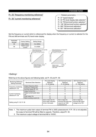
![OPERATION
55
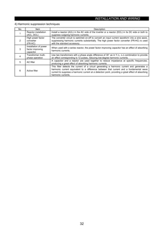
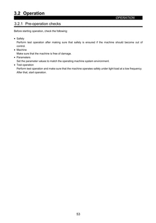
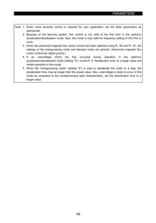
3.2.3 PU operation mode
(Operation using the operation panel (FR-DU04))
(1) Operation at 60Hz
While the motor is running, repeat the following steps 2 and 3 to vary the speed:
Step Description Image
1
Power-on → Operation mode check
Switch power on and make sure that the operation command
indication PU is lit.
(If it is not lit, switch to the PU operation mode.)
ON
REV FWD
2
Running frequency setting
Set the running frequency to 60Hz.
First, press the [MODE] key to select the frequency setting mode.
Then, press the [UP/DOWN] key to change the setting, and press
the [SET] key to write the frequency.
(or)
FR-DU04 CONTROL PANEL
Hz
MON EXT PU
A
V
REV FWD
3
Start
Press the [FWD] or [REV] key.
The motor starts running. The monitoring mode is automatically
selected and the output frequency is displayed.
REVFWD (or)
REV FWD
4
Stop
Press the [STOP] key.
The motor is decelerated to a stop.
FR-DU04 CONTROL PANEL
Hz
MON EXT PU
A
V
REV FWD
(2) PU jog operation
Hold down the [FWD] or [REV] key to perform operation, and release it to stop.
1) Set Pr. 15 jog frequency and Pr. 16 jog acceleration/deceleration.
2) Select the PU jog operation mode.
3) Hold down the [FWD] or [REV] key to perform operation.
(If the motor remains stopped, check Pr. 13 starting frequency. The motor will not start if its setting is
lower than the starting frequency.)](https://image.slidesharecdn.com/fr-a500-140613032347-phpapp01/85/Fr-a500-66-320.jpg)
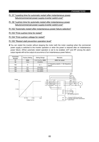
![OPERATION
56
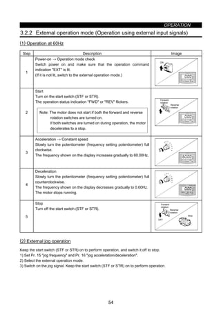
3.2.4 Combined operation mode
(Operation using the external input signals and PU)
When entering the start signal from outside the inverter and setting the running frequency from the PU
(Pr. 79 = 3)
The external frequency setting signals and the PU's FWD, REV and STOP keys are not accepted.
Step Description Image
1
Power-on
Switch power on.
ON
2
Operation mode selection
Set 3 in Pr. 79 operation mode selection.
The combined operation mode is selected and the operation status
indication EXT and PU are lit.
FR-DU04 CONTROL PANEL
Hz
MON EXT PU
A
V
REV FWD
3
Start
Turn on the start switch (STF or STR).
Note: The motor does not start if both the forward and reverse
rotation switches are turned on. If both switches are
turned on during operation, the motor decelerates (when
Pr. 250 = 9999) to a stop.
ON
Reverse
rotation
Forward
rotation
FR-DU04 CONTROL PANEL
Hz
MON EXT PU
A
V
REV FWD
4
Running frequency setting
Using the parameter unit, set the running frequency to 60Hz.
The operation command indication REV or FWD is lit.
· Select the frequency setting mode and make step setting.
Note: Step setting is the way of changing the frequency
consecutively by pressing the [UP/DOWN] key.
Hold down the [UP/DOWN] key to change the frequency.
Step setting
5
Stop
Turn off the start switch (STF or STR).
The motor stops running.
FR-DU04 CONTROL PANEL
Hz
MON EXT PU
A
V
REV FWD](https://image.slidesharecdn.com/fr-a500-140613032347-phpapp01/85/Fr-a500-67-320.jpg)
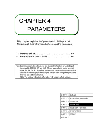
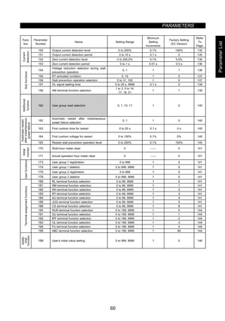
![4.2 Parameter Function Details
PARAMETERS
63
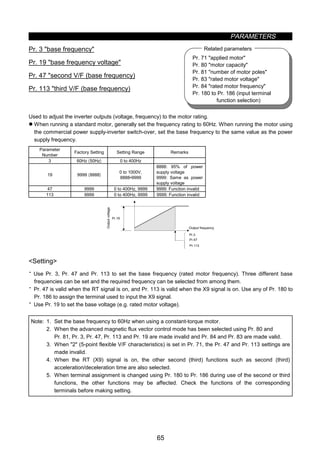
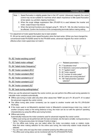
Pr. 3 base frequency
Pr. 19 base frequency voltage
Pr. 71 applied motor
Pr. 80 motor capacity
Pr. 81 number of motor poles
Pr. 180 to Pr. 186
(input terminal function selection)
Related parameters
4.2 Parameter Function Detailsz Torque boost (Pr. 0, Pr. 46, Pr. 112)
Pr. 0 torque boost
Pr. 46 second torque boost
Pr. 112 third torque boost
You can compensate for a voltage drop in the low frequency
range to improve motor torque reduction in the low speed range.
z Motor torque in the low-frequency range can be adjusted to the load to increase the starting motor torque.
z You can select any of the three different starting torque boosts by terminal switching.
Parameter
Number
Factory
Setting
Setting Range Remarks
0.4K, 0.75K 6%
1.5K to 3.7K 4%
5.5K, 7.5K 3%
0
11K or more 2%
0 to 30%
46 9999 0 to 30%, 9999 9999: Function invalid
112 9999 0 to 30%, 9999 9999: Function invalid
Pr.0
Pr.46
Pr.112
0
100%
Base frequency
Outputvoltage
Setting range
Output frequency (Hz)
Setting
x Assuming that the base frequency voltage is 100%, set the 0Hz voltage in %.
x A large setting will cause the motor to overheat. The guideline for maximum value is about 10%.
x Pr. 46 is valid when the RT signal is on. Pr. 112 is valid when the X9 signal is on. Use any of Pr. 180 to
Pr. 186 to assign the terminal used to input the X9 signal.
Note: 1. When using a constant-torque motor, change the setting of this parameter as follows:
0.4K, 0.75K...6%, 1.5K to 3.7k, 4%, 5.5K or more...2%
2. This parameter setting is ignored when Pr. 80 and Pr. 81 have been set to select the advanced
magnetic flux vector control mode.
3. When the Pr. 0 setting is either of the following values for 5.5K and 7.5K, it is automatically
changed when the Pr.71 setting is changed:
(1) When Pr. 0 setting is 3% (factory setting)
The Pr. 0 setting is changed to 2% automatically when the Pr. 71 setting is changed from
[general-purpose motor selection value (0, 2 to 8, 20, 23, 24)] to [constant-torque motor
selection value (1, 13 to 18)].
(2) When Pr. 0 setting is 2%
The Pr. 0 setting is changed to 3% (factory setting) automatically when the Pr. 71 setting is
changed from [constant-torque motor selection value (1, 13 to 18)] to [general-purpose motor
selection value (0, 2 to 8, 20, 23, 24)].
4. Increase the setting when the inverter-to-motor distance is long or motor torque in the low-speed
range is insufficient, for example. A too large setting may result in an overcurrent trip.
5. When the RT (X9) signal is on, the other second (third) functions such as second (third)
acceleration/deceleration time are also selected.
6. When terminal assignment is changed using Pr. 180 to Pr. 186 during use of the second or third
functions, the other functions may be affected. Check the functions of the corresponding
terminals before making setting.](https://image.slidesharecdn.com/fr-a500-140613032347-phpapp01/85/Fr-a500-75-320.jpg)
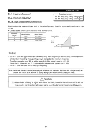
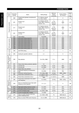
![PARAMETERS
66
Pr. 1 maximum frequency
Pr. 2 minimum frequency
Pr. 15 jog frequency
Pr. 28 multi-speed input compensation
Pr. 29 acceleration/deceleration
pattern
Pr. 79 operation mode selection
Pr. 180 to Pr. 186 (input terminal
function selection)
Related parameters
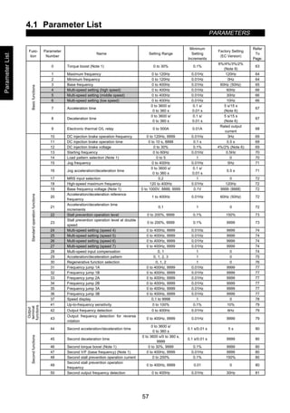
z Multi-speed operation (Pr. 4 to Pr. 6, Pr. 24 to Pr. 27, Pr. 232 to Pr. 239)
Pr. 4 3-speed setting (high speed)
Pr. 5 3-speed setting (middle speed)
Pr. 6 3-speed setting (low speed)
Pr. 24 to Pr. 27 multi-speed setting
(speeds 4 to 7)
Pr. 232 to Pr. 239 multi-speed setting
(speeds 8 to 15)
Used to preset the running speeds in parameters and switch between them using terminals.
z Any speed can be selected by switching on-off the contact signal (RH, RM, RL or REX signal).
z By using these functions with jog frequency (Pr. 15), maximum frequency (Pr. 1) and minimum frequency
(Pr. 2), up to 18 speeds can be set.
z Valid in the external operation mode or PU/external combined operation mode (Pr. 79 = 3 or 4).
Parameter
Number
Factory Setting Setting Range Remarks
4 60Hz 0 to 400Hz
5 30Hz 0 to 400Hz
6 10Hz 0 to 400Hz
24 to 27 9999 0 to 400Hz, 9999 9999: Not selected
232 to 239 9999 0 to 400Hz, 9999 9999: Not selected
ON
ON ON ON ON
ON ON
ONONON
ON
RH
RM
RL
REX
Speed 7
Outputfrequency
Speed 1
(high speed)
Speed 2
(middle speed)
Speed 3
(low speed)
Speed 4
Time
Speed 5
Speed 6
ONON ON ON ON ON ON ON
ON ON ON ON
ON ON ON ON
ON ON ON ON
RH
RM
RL
REX
Speed 15
Outputfrequency
Time
Speed 9
Speed 8
Speed 10
Speed 11
Speed 12
Speed 13
Speed 14
Setting
· Set the running frequencies in the corresponding parameters.
· Each speed (frequency) can be set as desired between 0 and 400Hz during inverter operation.
After the required multi-speed setting parameter has been read, the setting can be changed by pressing
the [UP/DOWN] key. (In this case, when you release the [UP/DOWN] key, press the [SET] key to store the
set frequency. When using the FR-PU04 (option), press the [WRITE] key.)
· Use any of Pr. 180 to Pr. 186 to assign the terminal used to input the REX signal.
Note: 1. The multi-speed settings override the main speeds (across terminals 2-5, 4-5).
2. The multi-speeds can also be set in the PU or external operation mode.
3. For 3-speed setting, if two or three speeds are simultaneously selected, priority is given to the
frequency setting of the lower signal.
4. Pr. 24 to Pr. 27 and Pr. 232 to Pr. 239 settings have no priority between them.
5. The parameter values can be changed during operation.
6. When terminal assignment is changed using Pr. 180 to Pr. 186, the other functions may be
affected. Check the functions of the corresponding terminals before making setting.](https://image.slidesharecdn.com/fr-a500-140613032347-phpapp01/85/Fr-a500-78-320.jpg)
![PARAMETERS
68
Pr. 71 applied motor
Related parameter
Note: 1. In S-shaped acceleration/deceleration pattern A (refer to page 75), the set time is a period
required to reach the base frequency set in Pr. 3.
· Acceleration/deceleration time calculation expression when the set frequency is the base
frequency or higher
t =
4
9
×
T
(Pr.3)2 × f
2
+
5
9 T
T: Acceleration/deceleration time setting (seconds)
f: Set frequency (Hz)
· Guideline for acceleration/deceleration time at the base frequency of 60Hz (0Hz to set
frequency)
Frequency setting (Hz)
Acceleration/
decelerationtime (seconds)
60 120 200 400
5 5 12 27 102
15 15 35 82 305
2. If the Pr. 20 setting is changed, the settings of calibration functions Pr. 903 and Pr. 905
(frequency setting signal gains) remain unchanged. To adjust the gains, adjust calibration
functions Pr. 903 and Pr. 905.
3. When the setting of Pr. 7, Pr. 8, Pr. 44, Pr. 45, Pr. 110 or Pr. 111 is 0, the
acceleration/deceleration time is 0.04 seconds. At this time, set 120Hz or less in Pr. 20.
4. When the RT (X9) signal is on, the other second (third) functions such as second (third) torque
boost are also selected.
5. If the shortest acceleration/deceleration time is set, the actual motor acceleration/deceleration
time cannot be made shorter than the shortest acceleration/deceleration time determined by the
mechanical system's GD
2
and motor torque.
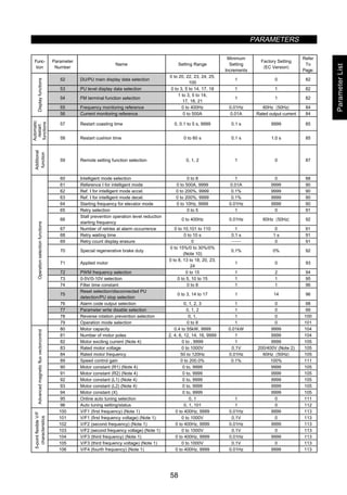
z Electronic overcurrent protection (Pr. 9)
Pr. 9 electronic overcurrent protection
Set the current of the electronic overcurrent protection to protect the motor from overheat. This feature
provides the optimum protective characteristics, including reduced motor cooling capability, at low speed.
Parameter
Number
Factory Setting Setting Range
9 Rated output current* 0 to 500A
*0.4K and 0.75K are set to 85% of the rated inverter current.
Setting
· Set the rated current [A] of the motor.
(Normally set the rated current value at 50Hz.)
· Setting of 0 makes the electronic overcurrent protection (motor protective function) invalid. (The inverter's
output transistor protective function is valid.)
· When Mitsubishi's constant-torque motor is used, set 1 or any of 13 to 18 in Pr. 71 to select the 100%
continuous torque characteristic in the low speed range. Then, set the rated motor current in Pr. 9.
Note: 1. When two or more motors are connected to the inverter, they cannot be protected by the
electronic overcurrent protection. Install an external thermal relay to each motor.
2. When a difference between the inverter and motor capacities is large and the setting is small, the
protective characteristics of the electronic overcurrent protection will be deteriorated. In this case,
use an external thermal relay.
3. A special motor cannot be protected by the electronic overcurrent protection. Use an external
thermal relay.](https://image.slidesharecdn.com/fr-a500-140613032347-phpapp01/85/Fr-a500-80-320.jpg)
![PARAMETERS
69
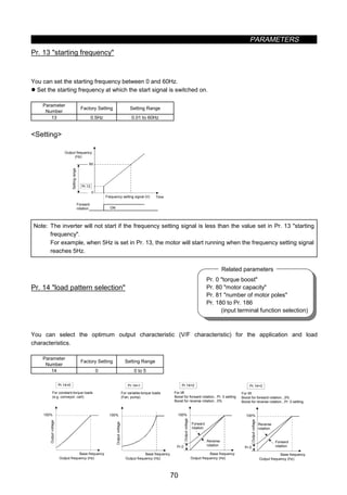
Pr. 13 starting frequency
Pr. 71 applied motor
Related parameters
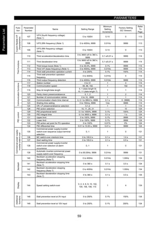
z DC dynamic brake (Pr. 10, Pr. 11, Pr. 12)
Pr. 10 DC dynamic brake operation frequency
Pr. 11 DC dynamic brake operation time
Pr. 12 DC dynamic brake voltage
By setting the stopping DC dynamic brake voltage (torque), operation time and operation starting frequency,
the stopping accuracy of positioning operation, etc. or the timing of operating the DC dynamic brake to stop
the motor is adjusted according to the load.
Parameter
Number
Factory
Setting
Setting Range Remarks
10 3Hz 0 to 120Hz, 9999
9999: Operated at
or below Pr. 13
value.
11 0.5 s 0 to 10 s, 8888
8888: Operated
when X13 signal
switches on.
7.5K or less 4%
12
11K or more 2%
0 to 30%
Pr.10
Pr.12
Pr.11 Operation time
Outputfrequency
Operation frequency
Time
DC dynamic
brake voltage
Operation voltage
Time
Setting
· Use Pr. 10 to set the frequency at which the DC dynamic brake application is started.
By setting 9999 in Pr. 10, the motor is decelerated to the frequency set in Pr. 13 and braked.
· Use Pr. 11 to set the period during when the brake is operated. By setting “8888” in Pr. 11, the DC dynamic
brake is operated while the X13 signal is on.
· Use any of Pr. 180 to Pr. 186 to assign the terminal used to input the X13 signal.
· Use Pr. 12 to set the percentage of the power supply voltage.
· When using the inverter dedicated motor (constant-torque motor), change the Pr. 12 setting as follows:
3.7K or less...4%, 5.5K or more...2%
Note: 1. When the Pr. 12 setting is either of the following values for 5.5K and 7.5K, it is automatically
changed when the Pr. 71 setting is changed:
(1) When Pr. 12 setting is 4% (factory setting)
The Pr. 12 setting is changed to 2% automatically when the Pr. 71 setting is changed from
[general-purpose motor selection value (0, 2 to 8, 20, 23, 24)] to [constant-torque motor
selection value (1, 13 to 18)].
(2) When Pr. 12 setting is 2%
The Pr. 12 setting is changed to 4% (factory setting) automatically when the Pr. 71 setting is
changed from [constant-torque motor selection value (1, 13 to 18)] to [general-purpose motor
selection value (0, 2 to 8, 20, 23, 24)].
2. When Pr. 11 = 0 or 8888 or Pr. 12 = 0, DC dynamic brake operation cannot be performed.
CAUTION
In the orientation (using option) mode, do not set 8888 in Pr. 11.
The motor may not be stopped in the correct position.
Install a mechanical brake. No holding torque is provided.](https://image.slidesharecdn.com/fr-a500-140613032347-phpapp01/85/Fr-a500-81-320.jpg)
![PARAMETERS
74
Pr. 59 remote setting function
Pr. 73 0-5V/0-10V selection
Related parameters
Setting
· In Pr. 22, set the stall prevention operation level. Normally set it to 150% (factory setting). Set 0 in Pr. 22
to disable the stall prevention operation.
· To reduce the stall prevention operation level in the high-frequency range, set the reduction starting
frequency in Pr. 66 and the reduction ratio compensation factor in Pr. 23.
Calculation expression for stall prevention operation level
Stall prevention operation level (%) = A + B × [
Pr.22-A
Pr.22-B ] × [
Pr.23-100
100 ]
where, A =
Pr.66 (Hz) × Pr.22 (%)
output frequency (Hz) , B =
Pr.66 (Hz) × Pr.22(%)
400Hz
· By setting 9999 (factory setting) in Pr. 23, the stall prevention operation level is constant at the Pr. 22
setting up to 400Hz.
· Set 9999 in Pr. 22 to vary the stall prevention operation level using the analog signal (0-5V/0-10V) entered
to the frequency setting auxiliary input terminal [1]. (Use Pr. 73 to select between 10V and 5V.)
· Use Pr. 148 and Pr. 149 to adjust the gain and bias of the analog signal.
· Set 0 in Pr. 154 to reduce the output voltage during stall prevention operation.
Note: 1. When Pr. 22 = 9999, terminal 1 is exclusively used for setting the stall prevention operation
level. The auxiliary input and override functions are not activated.
CAUTION
Do not set a too small value as the stall prevention operation current. Otherwise, torque
generated will reduce.
Test operation must be performed. Stall prevention operation during acceleration may
increase the acceleration time.
Stall prevention operation during constant speed may change the speed suddenly.
Stall prevention operation during deceleration may increase the deceleration time, increasing
the deceleration distance.
Pr. 24 to Pr. 27 Î Refer to Pr. 4 to Pr. 6.
z Multi-speed input compensation (Pr. 28)
Pr. 28 multi-speed input compensation
By entering a compensation signal into the frequency setting auxiliary input terminal 1 (Note 2), the speeds
(frequencies) of multi-speed settings or the speed setting made by remote setting function can be
compensated for.
Parameter
Number
Factory Setting Setting Range Remarks
28 0 0, 1
0: Not compensated,
1: Compensated
Note: 1. Use Pr. 73 to select the compensation input voltage between 0 to ±5V and 0 to ±10V.
2. When any of 4, 5, 14 and 15 is set in Pr. 73, the compensation signal is entered into terminal 2.
(Override functions)](https://image.slidesharecdn.com/fr-a500-140613032347-phpapp01/85/Fr-a500-86-320.jpg)
![PARAMETERS
75
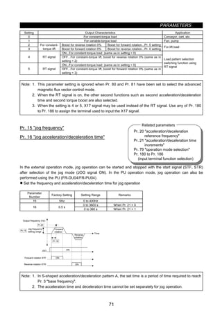
Pr. 3 base frequency
Pr. 7 acceleration time
Pr. 8 deceleration time
Pr. 20 acceleration/deceleration
reference frequency
Pr. 44 second acceleration/
deceleration time
Pr. 45 second deceleration time
Pr. 110 third acceleration/
deceleration time
Pr. 111 third deceleration time
Related parameters
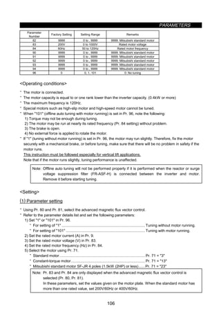
z Acceleration/deceleration pattern (Pr. 29, Pr. 140 to Pr. 143)
Pr. 29 acceleration/deceleration pattern
Pr. 140 backlash acceleration stopping frequency
Pr. 141 backlash acceleration stopping time
Pr. 142 backlash deceleration stopping frequency
Pr. 143 backlash deceleration stopping time
Set the acceleration/deceleration pattern.
Also, you can suspend acceleration/deceleration at set frequencies and for the time period set in the
parameters.
Parameter
Number
Factory Setting Setting Range Remarks
29 0 0, 1, 2, 3 3: Backlash compensation
140 1.00Hz 0 to 400Hz Valid when Pr. 29 = 3.
141 0.5 s 0 to 360 s Valid when Pr. 29 = 3.
142 1.00Hz 0 to 400Hz Valid when Pr. 29 = 3.
143 0 s 0 to 360 s Valid when Pr. 29 = 3.
t
Time
[Linear acceleration/deceleration]
Outputfrequency(Hz)
Set value 0
fb
t
[S-shaped acceleration/deceleration A]
Time
Outputfrequency(Hz)
Set value 1
f1
t
f2
[S-shaped acceleration/deceleration B]
Outputfrequency(Hz)
Time
Set value 2
t
∆f2 Pr.142
∆t2 Pr.143∆t1 Pr.141
∆f1 Pr.140
Outputfrequency(Hz)
Set value 3
[Backlash compensation function]
Time
Setting
Pr. 29
Setting
Function Description
0
Linear
acceleration/
deceleration
Linear acceleration/deceleration is made up/down to the preset frequency (factory setting).
1
S-shaped
acceleration/
deceleration A
(Note 1)
For machine tool spindles
This setting is used when it is necessary to make acceleration/deceleration in a short time up to the
60Hz or higher speed range. In this acceleration/deceleration pattern, fb (base frequency) is always the
inflection point of an S shape, and you can set the acceleration/deceleration time according to the
reduction in motor torque in the 60Hz or higher constant-output operation range.
2
S-shaped
acceleration/
deceleration B
Prevention of cargo collapse on conveyor, etc.
This setting provides S-shaped acceleration/deceleration from f2 (current frequency) to f1 (target
frequency), easing an acceleration/deceleration shock. This pattern has an effect on the prevention of
cargo collapse, etc.
3
Backlash
compensation
(Note 2, 3)
Backlash compensation for reduction gear, etc.
This function stops the speed change temporarily during acceleration/deceleration, reducing a shock
generated when a reduction gear backlash is eliminated suddenly. Use Pr. 140 to Pr. 143 to set the
stopping times and stopping frequencies in accordance with the above diagrams.
Note: 1. For the acceleration/deceleration time, set the time required to reach the base frequency in
Pr. 3, not the acceleration/deceleration reference frequency in Pr. 20. For details, refer to Pr. 7 and
Pr. 8.
2. Pr. 140 to Pr. 143 is accessible when 3 is set in Pr. 29.
3. The acceleration/deceleration time is increased by the stopping time.](https://image.slidesharecdn.com/fr-a500-140613032347-phpapp01/85/Fr-a500-87-320.jpg)
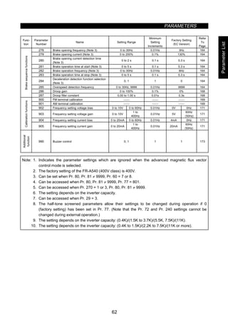
![PARAMETERS
94
z PWM carrier frequency (Pr. 72, Pr. 240)
Pr. 72 PWM frequency selection
Pr. 240 Soft-PWM setting
You can change the motor tone.
z By parameter setting, you can select Soft-PWM control which changes the motor tone.
z Soft-PWM control changes motor noise from a metallic tone into an unoffending complex tone.
Parameter
Number
Factory Setting Setting Range Remarks
72 2 0 to 15 0: 0.7kHz, 15: 14.5kHz
240 1 0, 1 1: Soft-PWM valid
Setting
· Refer to the following list and set the parameters:
Parameter
Number
Factory Setting Description
72 0 to 15
PWM carrier frequency can be changed.
The setting displayed is in [kHz]. Note that 0 indicates 0.7kHz and 15 indicates 14.5kHz.
0 Soft-PWM invalid
240
1 When any of 0 to 5 is set in Pr. 72, Soft-PWM is made valid.
Note: 1. A reduced PWM carrier frequency will decrease inverter-generated noise and leakage current but
increase motor noise.](https://image.slidesharecdn.com/fr-a500-140613032347-phpapp01/85/Fr-a500-106-320.jpg)
![PARAMETERS
96
z Input filter time constant (Pr. 74)
Pr. 74 filter time constant
You can set the input section's internal filter constant of an external voltage or current frequency setting
signal.
z Effective for eliminating noise in the frequency setting circuit.
z Increase the filter time constant if steady operation cannot be performed due to noise. A larger setting
results in lower response. (The time constant can be set between approximately 1ms to 1s. with the setting
of 0 to 8. A larger setting results in a larger filter time constant.)
Parameter
Number
Factory Setting Setting Range
74 1 0 to 8
z Reset selection/PU disconnection detection/PU stop selection (Pr. 75)
Pr. 75 reset selection/PU disconnection detection/PU stop selection
You can select the reset input acceptance, PU (FR-DU04/FR-PU04) connector disconnection detection
function and PU stop function.
• Reset selection : You can select the reset function input timing.
• PU disconnection detection : When it is detected that the PU (FR-DU04/FR-PU04) connector is
disconnected from the inverter for more than 1 second, the inverter outputs
an alarm code (E.PUE) and comes to an alarm stop.
• PU stop selection : When an alarm occurs in any operation mode, you can stop the motor from
the PU by pressing the [STOP] key.
Parameter
Number
Factory Setting Setting Range
75 14 0 to 3, 14 to 17
STF ON
(STR) OFF
Stop example for external operation
Speed
Operation panel
[SET] key
[STOP] key
Time
Setting
Pr. 75
Setting
Reset Selection PU Disconnection Detection PU Stop Selection
0 Reset input normally enabled.
1
Reset input enabled only when the
protective function is activated.
If the PU is disconnected, operation
will be continued.
2 Reset input normally enabled.
3
Reset input enabled only when the
protective function is activated.
When the PU is disconnected, the
inverter output is shut off.
Pressing the [STOP] key decelerates
the motor to a stop only in the PU
operation mode.
14 Reset input normally enabled.
15
Reset input enabled only when the
protective function is activated.
If the PU is disconnected, operation
will be continued.
16 Reset input normally enabled.
17
Reset input enabled only when the
protective function is activated.
When the PU is disconnected, the
inverter output is shut off.
Pressing the [STOP] key decelerates
the motor to a stop in any of the PU,
external and communication operation
modes.](https://image.slidesharecdn.com/fr-a500-140613032347-phpapp01/85/Fr-a500-108-320.jpg)
![PARAMETERS
97
How to make a restart after a stop made by the [STOP] key from the PU during external
operation
(1) Operation panel (FR-DU04)
1) After completion of deceleration to a stop, switch off the STF or STR signal.
2) Press the [MODE] key three times* to call the indication. (Note 8)
(*: For monitor screen)
3) Press the [SET] key.
4) Turn on the STF or STR signal.
(2) Parameter unit (FR-PU04)
1) After completion of deceleration to a stop, switch off the STF or STR signal.
2) Press the [EXT] key.
3) Switch on the STF or STR signal.
Note: 1. By entering the reset signal (RES) during operation, the inverter shuts off output while it is reset,
the data of the electronic overcurrent protection and regenerative brake duty are reset, and the
motor coasts.
2. The PU disconnection detection function judges that the PU connector is disconnected when it is
removed from the inverter for more than 1 second. If the PU had been disconnected before
power-on, it is not judged as an alarm.
3. To resume operation, reset the inverter after confirming that the PU is connected securely.
4. When PU disconnection detection is set and the PU is then disconnected during PU jog
operation, the motor decelerates to a stop. The motor will not stop if a PU disconnection alarm
occurs.
5. The Pr. 75 value can be set any time. Also, if parameter (all) clear is executed, this setting will not
return to the initial value.
6. When the motor is stopped by the PU stop function, PS is displayed but an alarm is not output.
When the PU connector is used for RS-485 communication operation, the reset selection and PU
stop selection functions are valid but the PU disconnection detection function is invalid.
7. The reset key of the PU is only valid when the protective function is activated, independent of the
Pr. 75 setting.
8. When Pr. 79 = 3, press the [MODE] key three times, then press the [UP/DOWN] key to display
.
CAUTION
Do not reset the inverter with the start signal on.
Otherwise, the motor will start instantly after resetting, which may lead to hazardous conditions.](https://image.slidesharecdn.com/fr-a500-140613032347-phpapp01/85/Fr-a500-109-320.jpg)
![PARAMETERS
101
Pr. 15 jog frequency
Pr. 4 to Pr. 6, Pr. 24 to 27, Pr.232 to
Pr.239
multi-speed operation
Pr. 76 alarm code output selection
Pr. 180 to Pr. 186
(input terminal function selection)
Pr. 200 to Pr. 231
programmed operation
Pr. 15 jog frequency
Pr. 4 to Pr. 6, Pr. 24 to 27, Pr.232 to
Pr.239
multi-speed operation
Pr. 76 alarm code output selection
Pr. 180 to Pr. 186
(input terminal function selection)
Pr. 200 to Pr. 231
programmed operation
Related parameters
z Operation mode selection (Pr. 79)
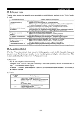
Pr. 79 operation mode selection
Used to select the operation mode of the inverter.
You can choose any of the operation modes: operation using external signals (external operation), operation
from the PU (FR-DU04/FR-PU04) (PU operation), combination of PU operation and external operation
(external/PU combined operation), and computer link operation (when the FR-A5NR option is used).
Parameter
Number
Factory Setting Setting Range
79 0 0 to 8
Setting
Pr. 79 Setting Function
0 PU or external operation can be selected.
1 PU operation mode
2 External operation mode
3
External/PU combined operation mode 1
Running frequency ..........Set from the PU (FR-DU04/FR-PU04) (direct setting, [UP/DOWN] key) or external
signal input (multi-speed setting only)
Start signal......................External signal input (terminal STF, STR)
4
External/PU combined operation mode 2
Running frequency ..........External signal input (terminal 2, 4, 1, jog, multi-speed selection)
Start signal......................Input from the PU (FR-DU04/FR-PU04) ([FWD] key, [REV] key)
5
Programmed operation mode
You can set 10 different operation starting times, rotation directions and running frequencies for each of three
groups.
Operation start. ............STF, timer reset...........STR
Group selection............RH, RM, RL
6
Switch-over mode
Switch-over between PU operation, external operation and computer link operation (when the communication
option such as the FR-A5NR is used) modes can be done while running.
7
External operation mode (PU operation interlock)
X12 signal ON.................May be switched to PU operation mode (output stop during external operation)
X12 signal OFF ...............Switching to PU operation mode inhibited
8
Switching to other than external operation mode (disallowed during operation)
X16 signal ON ................Switched to external operation mode
X16 signal OFF ...............Switched to PU operation mode
Note: 1. Either 3 or 4 may be set to select the PU/external combined operation. These settings differ in
starting method.
(1) Programmed operation
With this function, you can set 10 different operation starting times, rotation directions and running
frequencies individually for each of selected three groups to perform automatic operation under the
control of the internal elapsed time counting timer. For full information of this function, refer to the
explanations of Pr. 200 to Pr. 231.](https://image.slidesharecdn.com/fr-a500-140613032347-phpapp01/85/Fr-a500-113-320.jpg)
![PARAMETERS
103
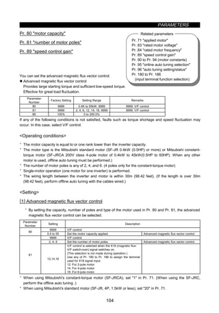
Function/operation changed by switching on-off the X12 (MRS) signal
Operating Condition
Operation
mode
Status
X12 (MRS)
Signal
Operation
Mode
(Note 4)
Operating Status Parameter Write
Switching
to PU
Operation
Mode
During stop
ON → OFF
(Note 3)
During stop Allowed → disallowed Disallowed
PU
During
operation
ON → OFF
(Note 3)
External
If external operation
frequency setting and start
signal are entered,
operation is performed in
that status.
Allowed → disallowed Disallowed
OFF → ON Disallowed → disallowed Allowed
During stop
ON → OFF
During stop
Disallowed → disallowed Disallowed
OFF → ON Disallowed → disallowed Disallowed → disallowed DisallowedExternal
During
operation ON → OFF
External
During operation →
output stop
Disallowed → disallowed Disallowed
Note: 1. When the Pr. 79 setting is 7 and the PU operation interlock signal is OFF, network operation such
as computer link cannot be used.
2. If the X12 (MRS) signal is on, the operation mode cannot be switched to the PU operation mode
when the start signal (STF, STR) is on.
3. The operation mode switches to the external operation mode independently of whether the start
signal (STF, STR) is on or off. Therefore, the motor is run in the external operation mode when
the X12 (MRS) signal is switched off with either of STF and STR on.
4. When an alarm occurs, the inverter can be reset by pressing the [RESET] key of the operation
panel.
5. When the MRS signal is used as the PU interlock signal, switching the MRS signal on and
rewriting the Pr. 79 value to other than 7 in the PU operation mode causes the MRS signal to
provide the ordinary MRS function (output stop). Also, as soon as 7 is set in Pr. 79, the MRS
signal acts as a PU interlock signal.
6. When the MRS signal is used as the PU external interlock signal, the signal logic conforms to the
Pr. 17 setting. When Pr. 17 = 2, read ON for OFF and OFF for ON in the above explanation.
(4) Operation mode external signal switching function
1) Preparation
Set 8 (switching to other than external operation mode) in Pr. 79. Using any of Pr. 180 to Pr. 186 (input
terminal function selection), allocate the terminal used to input the X16 (PU-external operation switching)
signal.
2) Function
When the X16 signal is switched on in the PU operation mode, the operation mode is forcibly changed to
the external operation mode. When the X16 signal is switched off in the external operation mode, the
operation mode is changed to the PU operation mode. When the X16 signal is switched off during network
operation such as computer link, the operation mode is changed to the PU operation mode as soon as the
switch-over command to the external operation mode is sent from the computer. Note that this switch-over
may only be made while the inverter is at a stop and cannot be made during operation.
X16 Signal Operation Mode
ON External operation mode (cannot be changed to the PU operation mode)
OFF PU operation mode (cannot be changed to the external operation mode)
Note: When terminal assignment is changed using Pr. 180 to Pr. 186, the other functions may be affected.
Check the functions of the corresponding terminals before making setting.](https://image.slidesharecdn.com/fr-a500-140613032347-phpapp01/85/Fr-a500-115-320.jpg)
![PARAMETERS
107
„ Parameter details
Parameter
Number
Setting Description
9 0 to 500A Set the rated motor current (A).
0
Electronic overcurrent protection thermal characteristics suitable for general-purpose
motor
1
Electronic overcurrent protection thermal characteristics suitable for Mitsubishi's
constant-torque motor
2
Electronic overcurrent protection thermal characteristics suitable for general-purpose
motor
5-point flexible V/F characteristics
20
Mitsubishi's SF-JR4P general-purpose motor (1.5kW (2HP) or less), Electronic
overcurrent protection thermal characteristics for advanced magnetic flux vector
control
3 Standard motor
13 Constant-torque motor
23
Mitsubishi's SF-JR4P standard motor
(1.5kW (2HP) or less)
Select offline auto tuning setting
4 Standard motor
14 Constant-torque motor
24
Mitsubishi's SF-JR4P standard motor
(1.5kW (2HP) or less)
Auto tuning read or change setting
enabled
5 Standard motor
15 Constant-torque motor
Star connection
6 Standard motor
16 Constant-torque motor
Delta connection
Direct input of
motor constants
enabled
7 Standard motor
17 Constant-torque motor
Star connection
8 Standard motor
71 (Note 1)
18 Constant-torque motor
Delta connection
Direct input of
motor constants
and offline auto
tuning
83 0 to 1000V Set the rated motor voltage (V).
84 50 to 120Hz Set the rated motor frequency (Hz).
90 0 to , 9999
91 0 to , 9999
92 0 to , 9999
93 0 to , 9999
9999
94
0 to 100%
Tuning data
(Values measured by offline auto tuning are set automatically.)
0 Offline auto tuning is not performed.
1 Offline auto tuning is performed without motor running.96 (Note 2)
101 Offline auto tuning is performed with motor running.
Note: 1. The electronic overcurrent protection characteristics are also selected simultaneously.
2. Select 101 to increase tuning accuracy.
(2) Tuning execution
· For PU operation, press the [FWD] or [REV] key.
· For external operation, switch on the run command.
Note: 1. When 101 is set in Pr. 96, guard against hazards because the motor rotates.
2. To force tuning to end
· Switch on the MRS or RES signal or press the [STOP] key to end.
· Switch off the tuning start command or make a forced stop.
3. During offline auto tuning, the following I/O signals are only valid:
· Input signals
STOP, OH, MRS, RT, CS, RES, STF, STR
· Output signals
RUN, OL, IPF, FM, AM, A, B, C
4. Special caution should be exercised when a sequence has been designed to open the
mechanical brake with the RUN signal.](https://image.slidesharecdn.com/fr-a500-140613032347-phpapp01/85/Fr-a500-119-320.jpg)
![PARAMETERS
108
(3) Monitoring the offline tuning status
When the parameter unit (FR-PU04) is used, the Pr. 96 value is displayed during tuning on the main
monitor as shown below. When the operation panel (FR-DU04) is used, only the same numerical value as
on the PU is displayed:
· Parameter unit (FR-PU04) main monitor
(For inverter trip)
1. Setting
2. Tuning in
progress
3. Completion 4. Error-activated end
STOP PU
1
FWD PU
2
STF
TUNE
STOP PU
3
STF
TUNE
COMPLETION
Display
STOP PU
101
FWD PU
102
STF
TUNE
STOP PU
103
STF
TUNE
COMPLETION
STOP PU
9
STF
TUNE
ERROR
· Operation panel (FR-DU04) display
(For inverter trip)
1. Setting
2. Tuning in
progress
3. Completion 4. Error-activated end
1 2 3Displayed
value
101 102 103
9
· Reference: Offline auto tuning time (factory setting)
Offline Auto Tuning Setting Time
1: No-rotation mode Approximately 25 seconds
2: Rotation mode
Approximately 40 seconds
(Offline auto tuning time varies with acceleration and deceleration time settings as
indicated below:
Offline auto tuning time = acceleration time + deceleration time + approximately 30
seconds)
(4) Ending the offline auto tuning
1) Confirm the Pr. 96 value.
· Normal end: 3 or 103 is displayed.
· Error-activated end: 9, 91, 92 or 93 is displayed.
· Forced end ... 8 is displayed.
2) When tuning ended normally.
For PU operation, press the [STOP] key. For external operation, switch off the start signal (STF or STR).
This operation resets the offline auto tuning and the PU's monitor display returns to the ordinary indication.
(Without this operation, next operation cannot be done.)
3) When tuning was ended due to an error.
Offline auto tuning did not end normally. (Motor constants have not been set.) Reset the inverter and start
tuning all over again.
4) Error display definitions.
Error Display Error Cause Remedy
9 Inverter trip Re-set.
91
Current limit (stall prevention) function was
activated.
Increase acceleration/deceleration time.
Set 1 in Pr. 156.
92
Inverter output voltage reached 75% of rated
value.
Check for fluctuation of power supply voltage.
93 Calculation error Check the motor wiring and re-set.
No connection with motor will result in 93 error.](https://image.slidesharecdn.com/fr-a500-140613032347-phpapp01/85/Fr-a500-120-320.jpg)
![PARAMETERS
109
5) When tuning was forced to end
A forced end occurs when tuning is forced to end by pressing the [STOP] key or turning off the start signal
(STF or STR) during tuning.
In this case, offline auto tuning was not brought to a normal end. (The motor constants are not yet set.)
Reset the inverter and restart tuning.
Note: 1. The motor constants measured once in the offline auto tuning are stored as parameters and their
data is held until the offline auto tuning is performed again.
2. An instantaneous power failure occurring during tuning will result in a tuning error. After power is
restored, the inverter goes into the ordinary operation mode. Therefore, when STF (STR) is on,
the motor runs in forward (reverse) rotation.
3. When 8888 is set in Pr. 11, the tuning is forced to end and the DC dynamic brake is started
upon input of the MRS signal.
4. Any alarm occurring during tuning is handled as in the ordinary mode.
Note that if an error retry has been set, retry is ignored.
5. The set frequency monitor displayed during the offline auto tuning is 0Hz.
CAUTION
Note that the motor may start running suddenly.
When the offline auto tuning is used in vertical lift application, e.g. a lifter, it may drop due to
insufficient torque.
Setting the motor constants as desired
The motor constants (Pr. 90 to Pr. 94) may be set as desired in either of two ways; the data measured
in the offline auto tuning is read and utilized or changed, or the motor constants are set without the
offline
auto tuning data being used.
„ To utilize or change the offline auto tuning data
Operating procedure
1. Set 801 in Pr. 77. Only when the Pr. 80 and Pr. 81 settings are other than 9999, the parameter
values of the motor constants (Pr. 90 to Pr. 94) can be displayed. Though the parameter values of
other than the motor constants (Pr. 90 to Pr. 94) can also be displayed, they are parameters for
manufacturer setting and should be handled carefully without misuse.
2. Set any of the following values in Pr. 71:
· Standard motor...................................................................................... Pr. 71 = 4
· Constant-torque motor........................................................................... Pr. 71 = 14
· Mitsubishi standard motor SF-JR 4 poles (1.5kW (2HP) or less).......... Pr. 71 = 24
3. In the parameter setting mode, read the following parameters and set desired values. (Note 1)
Parameter
Number
Name Setting Range
Setting
Increments
Factory
Setting
82 Motor exciting current 0 to ****, 9999 1 9999
90 Motor constant R1 0 to ****, 9999 1 9999
91 Motor constant R2 0 to ****, 9999 1 9999
92 Motor constant L1 0 to ****, 9999 1 9999
93 Motor constant L2 0 to ****, 9999 1 9999
94 Motor constant X 0 to ****, 9999 1 9999
4. Return the Pr. 77 setting to the original value.](https://image.slidesharecdn.com/fr-a500-140613032347-phpapp01/85/Fr-a500-121-320.jpg)
![PARAMETERS
110
Note: 1. Pr. 90 to Pr. 94 values may only be read when the Pr. 80 and Pr. 81 settings are other than
9999 (advanced magnetic flux vector control selected).
2. Set 9999 in Pr. 90 to Pr. 94 to use the standard motor constants (including those for the
constant-torque motor).
3. Set 3 (standard motor), 13 (constant-torque motor) or 23 (Mitsubishi standard motor SF-JR
4P (1.5kW (2HP) or less)) in Pr. 71 to use the constants measured in the offline auto tuning. Set
4, 14 or 24 in Pr. 71 and change the motor constants to change the values measured in the
offline auto tuning.
4. As the motor constants measured in the offline auto tuning have been converted into internal data
(****), refer to the following setting example when making setting:
Setting example: To slightly increase Pr. 90 value
When Pr. 90 is displayed 2516, set 2642, i.e. 2516×1.05=2641.8, in Pr. 90.
(The value displayed has been converted into a value for internal use. Hence, simple addition of a
given value to the displayed value has no significance.)
„ To set the motor constants without using the offline auto tuning data
The Pr. 92 and Pr. 93 motor constants may either be entered in [Ω] or in [mH]. Before starting
operation, confirm which motor constant unit is used.
z To enter the Pr. 92 and Pr. 93 motor constants in [Ω]
Operating procedure
1. Set 801 in Pr. 77. Only when the Pr. 80 and Pr. 81 settings are other than 9999, the parameter
values of the motor constants (Pr. 90 to Pr. 94) can be displayed. Though the parameter values
of other than the motor constants (Pr. 90 to Pr. 94) can also be displayed, they are parameters
for manufacturer setting and should be handled carefully without misuse.
2. Set any of the following values in Pr. 71:
Star Connection Motor Delta Connection Motor
Standard motor 5 6
Setting
Constant-torque motor 15 16
3. In the parameter setting mode, read the following parameters and set desired values:
Parameter
Number
Name Setting Range
Setting
Increments
Factory
Setting
90 Motor constant R1 0 to 10Ω, 9999 0.001Ω 9999
91 Motor constant R2 0 to 10Ω, 9999 0.001Ω 9999
92 Motor constant X1 0 to 10Ω, 9999 0.001Ω 9999
93 Motor constant X2 0 to 10Ω, 9999 0.001Ω 9999
94 Motor constant X 0 to 500Ω, 9999 0.01Ω 9999
4. Refer to the following table and set Pr. 84:
Parameter
Number
Name Setting Range
Setting
Increments
Factory
Setting
84 Rated motor frequency 50 to 120Hz 0.01Hz 60Hz 〈50Hz〉
5. Return the Pr. 77 setting to the original value.
Note: 1. Pr. 90 to Pr. 94 values may only be read when the Pr. 80 and Pr. 81 settings are other
than 9999 (advanced magnetic flux vector control selected).
2. Set 9999 in Pr. 90 to Pr. 94 to use the standard motor constants (including those for the
constant-torque motor).
3. If star connection is mistaken for delta connection or vice versa during setting of Pr.
71, advanced magnetic flux vector control cannot be exercised normally.](https://image.slidesharecdn.com/fr-a500-140613032347-phpapp01/85/Fr-a500-122-320.jpg)
![PARAMETERS
111
Pr. 71 applied motor
Pr. 80 motor capacity
Pr. 81 number of motor poles
Pr. 83 rated motor voltage
Pr. 84 rated motor frequency
Pr. 89 speed control gain
Pr. 90 to Pr. 94 (motor constants)
Pr. 96 auto tuning setting/status
Related parameters
z To enter the Pr. 92 and Pr. 93 motor constants in [mH]
Operating procedure
1. Set 801 in Pr. 77. Only when the Pr. 80 and Pr. 81 settings are other than 9999, the parameter
values of the motor constants (Pr. 90 to Pr. 94) can be displayed. Though the parameter (Pr. 82 to
Pr. 99) values of other than the motor constants (Pr. 90 to Pr. 94) can also be displayed, they are
parameters for manufacturer setting and should be handled carefully without misuse.
2. Set any of the following values in Pr. 71:
· Standard motor...................................................................................... Pr. 71 = 0
· Constant-torque motor........................................................................... Pr. 71 = 1
· Mitsubishi standard motor SF-JR 4 poles (1.5kW (2HP) or less).......... Pr. 71 = 20
3. In the parameter setting mode, read the following parameters and set desired values:
Parameter
Number
Name Setting Range
Setting
Increments
Factory
Setting
90 Motor constant R1 0 to 50Ω, 9999 0.001Ω 9999
91 Motor constant R2 0 to 50Ω, 9999 0.001Ω 9999
92 Motor constant L1 0 to 1000mH, 9999 0.1mH 9999
93 Motor constant L2 0 to 1000mH, 9999 0.1mH 9999
94 Motor constant X 0 to 100%, 9999 0.1% 9999
4. Refer to the following table and set Pr. 84:
Parameter
Number
Name Setting Range
Setting
Increments
Factory
Setting
84 Rated motor frequency 50 to 120Hz 0.01Hz 60Hz 〈50Hz〉
5. Return the Pr. 77 setting to the original value.
Note: 1. Pr.90 to Pr. 94 values may only be read when the Pr. 80 and Pr. 81 settings are other than
9999 (advanced magnetic flux vector control selected).
2. Set 9999 in Pr. 90 to Pr. 94 to use the standard motor constants (including those for the
constant-torque motor).
Pr. 89 Î Refer to Pr. 80.
z Online auto tuning selection (Pr. 95)
Pr. 95 online auto tuning selection
By online auto tuning, the motor conditions are tuned rapidly at the start. This enables precise operation
unaffected by motor temperatures and steady high-torque operation down to super-low speed. After setting
the Pr. 80 and Pr. 81 values, select online auto tuning with Pr. 95.
z Online auto tuning
Use this function when steady high-torque operation is required for low-speed operation under advanced
magnetic flux vector control.
· Before starting the online auto tuning, perform the offline auto tuning. Data must be calculated.](https://image.slidesharecdn.com/fr-a500-140613032347-phpapp01/85/Fr-a500-123-320.jpg)
![PARAMETERS
115
z For the data codes of the parameters, refer to the data code list in the appendices.
Parameter
Number
Factory
Setting
Setting Range
117 0 0 to 31
118 192 48, 96, 192
Data length 8 0, 1
119 1
Data length 7 10, 11
120 2 0, 1, 2
121 1 0 to 10, 9999
122 0 9999 0 to 999.8 sec, 999
123 9999 0 to 150ms, 9999
124 1 0, 1, 2
Setting
To make communication between the personal computer and inverter, the communication specifications
must be set to the inverter initially. If initial setting is not made or there is a setting fault, data transfer cannot
be made.
Note: After making the initial setting of the parameters, always reset the inverter. After you have changed the
communication-related parameters, communication cannot be made if the inverter is not reset.
Parameter
Number
Name Setting Description
117
Station
number
0 to 31
Station number specified for communication from the PU connector.
Set the inverter station numbers when two or more inverters are connected to one
personal computer.
48 4800 baud
96 9600 baud118
Communi-
cation
speed 192 19200 baud
0 Stop bit length 1 bit
8 bits
1 Stop bit length 2 bits
10 Stop bit length 1 bit
119
Stop bit
length/data
length 7 bits
11 Stop bit length 2 bits
0 Absent
1 Odd parity present120
Parity check
presence/
absence 2 Even parity present
0 to 10
Set the permissible number of retries at occurrence of data receive error. If the
number of consecutive errors exceeds the permissible value, the inverter will come
to an alarm stop.
121
Number of
communica-
tion retries 9999
(65535)
If a communication error occurs, the inverter will not come to an alarm stop. At this
time, the inverter can be coasted to a stop by MRS or RESET input.
During an error, the light fault signal (LF) is given to the open collector output.
Allocate the used terminal with any of Pr. 190 to Pr. 195 (output terminal function
selection).
0 No communication
0.1 to 999.8 Set the communication check time [sec] interval.
122
Communi-
cation
check time
interval
9999
If a no-communication state persists for longer than the permissible time, the
inverter will come to an alarm stop.
0 to 150ms Set the waiting time between data transmission to the inverter and response.
123
Waiting
time setting 9999 Set with communication data.
0 Without CR/LF
1 With CR
124
CR, LF
presence/
absence
selection
2 With CR/LF](https://image.slidesharecdn.com/fr-a500-140613032347-phpapp01/85/Fr-a500-127-320.jpg)
![PARAMETERS
116
Computer programming
(1) Communication protocol
Data communication between the computer and inverter is performed using the following procedure:
*1
*2
Computer
Inverter
↓ (Data flow)
Computer
↓ (Data flow)
Inverter
Data read
Data write
Time
1)
2) 3)
4)
5)
*1. If a data error is detected and a retry must be made, execute retry operation from the user program.
The inverter comes to an alarm stop if the number of consecutive retries exceeds the parameter
setting.
*2. On receipt of a data error occurrence, the inverter returns “reply data 3” to the computer again. The
inverter comes to an alarm stop if the number of consecutive data errors reaches or exceeds the
parameter setting.
(2) Communication operation presence/absence and data format types
Communication operation presence/absence and data format types are as follows:
No. Operation
Run
Command
Running
Frequency
Parameter
Write
Inverter Reset Monitoring
Parameter
Read
1)
Communication request is sent to the
inverter in accordance with the user
program.
A’ A A A B B
2) Inverter data processing time Present Present Present Absent Present Present
No error
Request accepted
C C C Absent
E
E’
E
3)
Reply data from the
inverter
(Data 1 is checked for
error)
With error
request rejected
D D D Absent F F
4) Computer processing delay time Absent Absent Absent Absent G G
No error
No processing
Absent Absent Absent Absent G G
5)
Answer from
computer in response
to reply data 3
(Data 3 is checked for
error)
With error data
3 is output
Absent Absent Absent Absent H H
(3) Data format
Hexadecimal data is used. Data is automatically transferred in ASCII between the computer and inverter.
1) Data format types
(1) Communication request data from computer to inverter
*3
ENQ
*4
1 2 3 4 5 6 7 8 9 10 11 12 13
*3
ENQ
*4
1 2 3 4 5 6 7 8 9 10 11
*3
ENQ
*4
1 2 3 4 5 6 7 8 9
[Data format]
Format A
[Data read]
Format A'
Format B
Inverter
station
number
Instruction
code
*5
Waiting
time
Data
Sum
sheck
Inverter
station
number
Inverter
station
number
Instruction
code
Instruction
code
*5
Waiting
time
*5
Waiting
time
Data
Sum
sheck
Sum
sheck
←Number of characters
←Number of characters
←Number of characters](https://image.slidesharecdn.com/fr-a500-140613032347-phpapp01/85/Fr-a500-128-320.jpg)
![PARAMETERS
117
Note: 1. The inverter station numbers may be set between H00 and H1F (stations 0 and 31) in
hexadecimal.
2. *3 indicates the control code.
3. *4 indicates the CR or LF code.
When data is transmitted from the computer to the inverter, codes CR (carriage return)
and LF (line feed) are automatically set at the end of a data group on some computers. In
this case, setting must also be made from the inverter according to the computer.
Also, the presence and absence of the CR and LF codes can be selected using Pr. 124.
4. *5: When Pr. 123 waiting time setting ≠ 9999, create the communication request data
with no waiting time in the data format. (The number of characters decreases by 1.)
2) Send data from computer to inverter during data write
*3
ACK
*4
1 2 3 4
*3
NAK
1 2 3 4
*4
5
[No data error detected] [Data error detected]
Format C Format D
Inverter
station
number
Inverter
station
number
Error
code
←Number of characters←Number of characters
3) Reply data from inverter to computer during data read
1 2 3 4 5
1 2 3 4 5 6 7 8 9 10 11
[No data error detected]
1 2 3 4 5 6 7 8 9
*3
STX
Format E
Inverter
station
number
Read
data
Sum
check
←Number of characters
Format E'
*3
ETX
*4Read data
Inverter
station
number
Sum
check
*4
*3
ETX
*3
STX
[Data error detected]
Format F
*3
NAK
Error
code
*4
Inverter
station
number
4) Reply data from computer to inverter during data read
1 2 3 4 1 2 3 4
[No data error detected]
*3
ACK
Format G
Inverter
station
number
←Number of characters
Format H*4
*3
NAK
[Data error detected]
*4
Inverter
station
number
←Number of characters
(4) Data definitions
1) Control codes
Signal ASCII Code Description
STX H02 Start of Text (Start of data)
ETX H03 End of Text (End of data)
ENQ H05 Enquiry (Communication request)
ACK H06 Acknowledge (No data error detected)
LF H0A Line Feed
CR H0D Carriage Return
NAK H15 Negative Acknowledge (Data error detected)
2) Inverter station number
Specify the station number of the inverter which communicates with the computer.
3) Instruction code
Specify the processing request (e.g. operation, monitoring) given by the computer to the inverter. Hence,
the inverter can be run and monitored in various ways by specifying the instruction code as appropriate.
4) Data
Indicates the data such as frequency and parameters transferred to and from the inverter. The definitions
and ranges of set data are determined in accordance with the instruction codes. (Refer to Appendix 1.)](https://image.slidesharecdn.com/fr-a500-140613032347-phpapp01/85/Fr-a500-129-320.jpg)
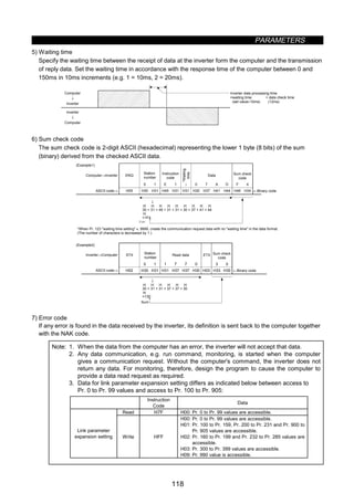
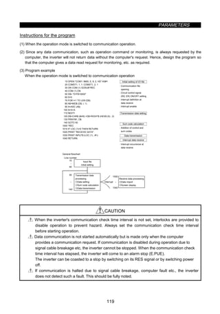
![PARAMETERS
120
Setting items and set data
After completion of parameter setting, set the instruction codes and data and start communication from
the computer to allow various types of operation control and monitoring.
No. Item
Instruction
Code
Description
Number of
Data Digits
Read H7B
H0000: Communication option operation
H0001: External operation
H0002: Communication operation (PU connector)
1
Operation
mode
Write HFB
H0000: Communication option operation
H0001: External operation
H0002: Communication operation (PU connector)
4 digits
Output frequency
[speed]
H6F
H0000 to HFFFF: Output frequency (hexadecimal) in 0.01Hz
increments
[Speed (hexadecimal) in 1r/min increments if Pr. 37 = 1 to
9998 or Pr. 144 = 2 to 10, 102 to 110.]
4 digits
Output current H70
H0000 to HFFFF: Output current (hexadecimal) in 0.1A
increments
4 digits
Output voltage H71
H0000 to HFFFF: Output voltage (hexadecimal) in 0.1V
increments
4 digits
Special monitor H72
H0000 to HFFFF: Monitored data selected by instruction code
HF3
4 digits
H01 to H0E Monitor selection data
Data Description
Incre-
ments
Data Description
Incre-
ments
H01
Output
frequency
0.01Hz H09
Regenerative
brake
0.1%Read H73
H02 Output current 0.01A H0A
Electronic
overcurrent
protection load
factor
0.1%
H03 Output voltage 0.1V H0B
Output current
peak value
0.01A
H05
Frequency
setting
0.01Hz H0C
Converter output
voltage peak value
0.1V
H06 Running speed r/min H0D Input power 0.01kW
H07 Motor torque 0.1% H0E Output power 0.01kW
Special monitor
selection No.
Write HF3
2 digits
H0000 to HFFFF: Two most recent alarm definitions
Read data: [Example] H30A0
Most recent alarm
(HA0)
b15 b8b7 b0
0 0 1 1 0 0 0 0 0 0 0 0 00 1 1
(Previous alarm ........ THT)
(Most recent alarm ..... OPT)
Previous alarm
(H30)
Alarm data
Data Description Data Description Data Description
H00 No alarm H51 UVT HB1 PUE
H10 0C1 H60 OLT HB2 RET
H11 0C2 H70 BE HC1 CTE
H12 0C3 H80 GF HC2 P24
H20 0V1 H81 LF HD5 MB1
H21 0V2 H90 OHT HD6 MB2
H22 0V3 HA0 OPT HD7 MB3
H30 THT HA1 OP1 HD8 MB4
H31 THM HA2 OP2 HD9 MB5
H40 FIN HA3 OP3 HDA MB6
H50 IPF HB0 PE HDB MB7
2
Monitoring
Alarm definition H74 to H77 2 digits](https://image.slidesharecdn.com/fr-a500-140613032347-phpapp01/85/Fr-a500-132-320.jpg)
![PARAMETERS
121
No. Item
Instruction
Code
Description
Number
of Data
Digits
3 Run command HFA
b0:
b1: Forward rotation (STF)
b2: Reverse rotation (STR)
b3:
b4:
b5:
b6:
b7:
H00 to HFF: Run command
0 0 0 0 0 0 01
b7 b0
[Example 1] H02
... Forward rotation
[Example 2] H00
... Stop
(For example 1)
2 digits
4
Inverter status
monitor
H7A
b0: Inverter running (RUN) *
b1: Forward rotation (STF)
b2: Reverse rotation (STR)
b3: Up to frequency (SU) *
b4: Overload (OL) *
b5: Instantaneous power
failure (IPF) *
b6: Frequency detection (FU) *
b7: Alarm occurrence *
H00 to HFF: Inverter status monitor
0 0 0 0 0 0 01
b7
[Example 1] H02
... During forward rotation
[Example 2] H80
... Stop due to alarm
(For example 1)
*The output data depends on the Pr. 190 to Pr. 195 settings.
2 digits
5
Running frequency
write
(E
2
PROM)
HEE
H0000 to H9C40: 0.01Hz increments (hexadecimal)
(0 ≠ 400.00 Hz)
To change the running frequency consecutively, write data to the
inverter RAM. (Instruction code: HED)
4 digits
6 Inverter reset HFD
H9696: Resets the inverter.
As the inverter is reset on start of communication by the computer, the
inverter cannot send reply data back to the computer.
4 digits
All parameters return to the factory settings.
Any of four different clear operations is performed according to the data.
Pr.
Data
Communi-
cation Pr.
Calibration Other Pr.
HEC
HF3
HFF
H9696 { × { {
H9966 { { { {
H5A5A × × { {
H55AA × { { {
7 All clear HFC
When all parameter clear is executed for H9696 or H9966,
communication-related parameter settings also return to the factory
settings. When resuming operation, set the parameters again.
4 digits
H9669: User clear is made.
Communi-
cation Pr.
Calibration Other Pr.
HEC
HFC
HFF
{ × { {
8 User clear HFC 4 digits
9 Parameter write H80 to HE3
10 Parameter read H00 to H63
Refer to the data list (Appendix 1) and write and/or read parameter
values as required.
Note that some parameters may not be accessible.
4 digits
Read H7F
11
Link
parameter
expansion
setting Write HFF
H00 to H6C and H80 to HEC parameter values are changed.
H00: Pr. 0 to Pr. 99 values are accessible.
H01: Pr. 100 to Pr. 159 , Pr. 200 to Pr. 231 and Pr. 900 to Pr. 905
values are accessible.
H02: Pr. 160 to Pr. 199 and Pr. 232 to Pr. 285 values are accessible.
H03: Pr. 300 to Pr. 399 values are accessible.
H09: Pr. 990 value is accessible.
2 digits
Read H6C
When setting the programmed operation
(data code H3D to H5A, H8D to HAD)
parameter
H00: Time
H01: Time
H02: Rotation direction
6 3 3 B
Time (Min.) Min. (Sec.)
12
Second
parameter
changing
(Code
FF = 1)
Write HEC
When setting the bias/gain (data code H5E to H6A, HDE to HED)
parameter
H00: Offset/gain
H01: Analog
H02: Analog value of terminal
2 digits](https://image.slidesharecdn.com/fr-a500-140613032347-phpapp01/85/Fr-a500-133-320.jpg)
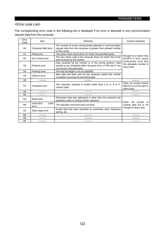
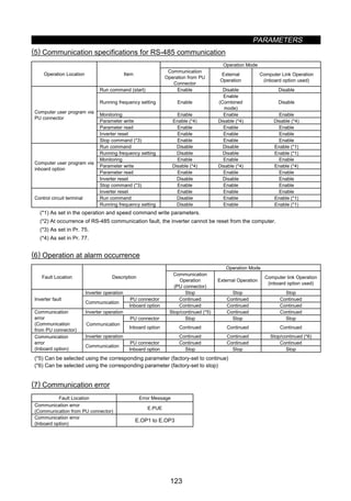
![PARAMETERS
124
Pr. 73 0-5V/0-10V selection
Pr. 79 operation mode selection
Pr. 180 to Pr. 186
(input terminal assignment)
Pr. 191 to Pr. 194
(output terminal assignment)
Pr. 902 to Pr. 905
(frequency setting voltage
(current) biases and gains)
Related parameters
z PID control (Pr. 128 to Pr. 134)
Pr. 128 PID action selection
Pr. 129 PID proportional band
Pr. 130 PID integral time
Pr. 131 upper limit
Pr. 132 lower limit
Pr. 133 PID action set point for PU operation
Pr. 134 PID differential time
The inverter can be used to exercise process control, e.g. flow rate, air volume or pressure.
z The voltage input signal (0 to ±5V or 0 to ±10V) or Pr. 133 setting is used as a set point and the 4 to
20mADC current input signal used as a feedback value to constitute a feedback system for PID control.
Parameter
Number
Factory Setting Setting Range Remarks
128 10 10, 11, 20, 21
129 100% 0.1 to 1000%, 9999 9999: No proportional control
130 1 s 0.1 to 3600 s, 9999 9999: No integral control
131 9999 0 to 100%, 9999 9999: Function invalid
132 9999 0 to 100%, 9999 9999: Function invalid
133 0% 0 to 100%
134 9999 0.01 to 10.00 s, 9999 9999: No differential control
Setting
(1) Basic PID control configuration
+
-
x
y
fi
IM
y
U
Ti ‚ S
1
1+ +Td ‚ S
Kp: Proportional constant Ti: Integral time S: Operator Td: Differential time
Set point
Deviation
Kp
PID
operation
Manipulated
variable
Inverter
drive circuit
Motor
Process value
(2) PID action overview
1) PI action
A combination of proportional control action (P) and integral control action (I) for providing a manipulated
variable in response to deviation and changes with time.
[Operation example for stepped changes of process value]
Note: PI action is the sum of P and I actions.
Time
Time
Time
Process value
P action
I action
PI action
Deviation Set point](https://image.slidesharecdn.com/fr-a500-140613032347-phpapp01/85/Fr-a500-136-320.jpg)
![PARAMETERS
125
2) PD action
A combination of proportional control action (P) and differential control action (D) for providing a
manipulated variable in response to deviation speed to improve the transient characteristic.
[Operation example for proportional changes of process value]
Note: PD action is the sum of P and D actions.
Time
Time
Time
Deviation
P action
D action
PD action
Set point
Process
value
3) PID action
The PI action and PD action are combined to utilize the advantages of both actions for control.
Note: The PID action is the sum of P and I and D actions.
4) Reverse action
Increases the manipulated variable (output frequency) if deviation X (set point - process value) is positive,
and decreases the manipulated variable if deviation is negative.
X0
X0
+
-
Process value
Set point
[Heating]
Process value
Cold → fi up
Hot → fi down
Deviation Set point
5) Forward action
Increases the manipulated variable (output frequency) if deviation X (set point - process value) is negative,
and decreases the manipulated variable if deviation is positive.
X0
X0
+
-
Set point
Too cold → fi down
Hot → fi up
Set point
[Cooling]
Process value
Process value
Deviation
Relationships between deviation and manipulated variable (output frequency)
Deviation
Positive Negative
Reverse action Ò Ô
Forward action Ô Ò](https://image.slidesharecdn.com/fr-a500-140613032347-phpapp01/85/Fr-a500-137-320.jpg)
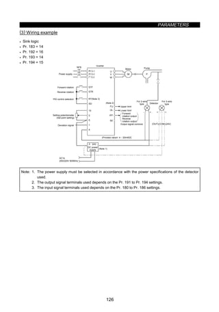
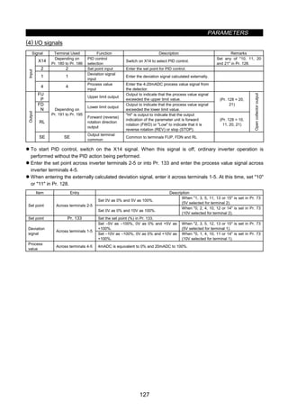
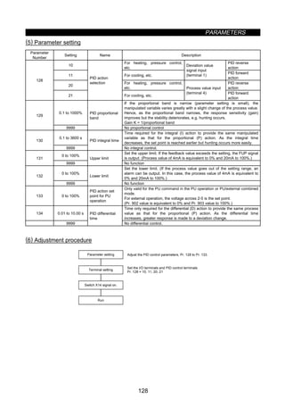
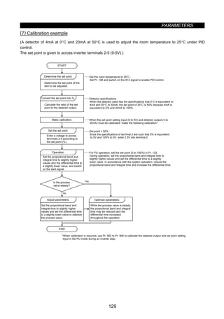
![PARAMETERS
130
Set point input calibration
1. Apply the input voltage of 0% set point setting (e.g. 0V) to across terminals 2-5.
2. Make calibration using Pr. 902. At this time, enter the frequency which should be output by the inverter at
the deviation of 0% (e.g. 0Hz).
3. Apply the voltage of 100% set point setting (e.g. 5V) to across terminals 2-5.
4. Make calibration using Pr. 903. At this time, enter the frequency which should be output by the inverter at
the deviation of 100% (e.g. 60Hz).
Detector output calibration
1. Apply the output current of 0% detector setting (e.g. 4mA) to across terminals 4-5.
2. Make calibration using Pr. 904.
3. Apply the output current of 100% detector setting (e.g. 20mA) to across terminals 4-5.
4. Make calibration using Pr. 905.
Note: The frequencies set in Pr. 904 and Pr. 905 should be the same as set in Pr. 902 and Pr. 903. The
results of the above calibration are as shown below:
100
0
0 5 (V)
%
[Set point setting]
100
0
0 20 (mA)
%
4
[Detection value]
60
0
0 100 Deviation (%)
[Manipulated variable]
Manipulated
variable (Hz)
Note: 1. If the multi-speed (RH, RM, RL) signal or jog operation (jog) signal is entered with the X14 signal
on, PID control is stopped and multi-speed or jog operation is started.
2. When 20 or 21 is set in Pr. 128, note that the input across inverter terminals 1-5 is added to
the set point across terminals 2-5.
3. When 5 (programmed operation mode) is selected for Pr. 79, PID control operation cannot be
performed. In this setting, programmed operation is performed.
4. When 6 (switch-over mode) is selected for Pr. 79, PID is made invalid.
5. When 9999 is set in Pr. 22, the stall prevention level is the value entered from terminal 1. When
using terminal 1 as the edit input terminal for PID, therefore, set a value other than 9999 in
Pr. 22.
6. When 1 (online auto tuning) is selected for Pr. 95, PID control is made invalid.
7. When the terminal functions are changed using Pr. 180 to Pr. 186 and/or Pr. 190 to Pr. 195, the
other functions may be affected. Confirm the functions of the corresponding terminals before
making settings.](https://image.slidesharecdn.com/fr-a500-140613032347-phpapp01/85/Fr-a500-142-320.jpg)
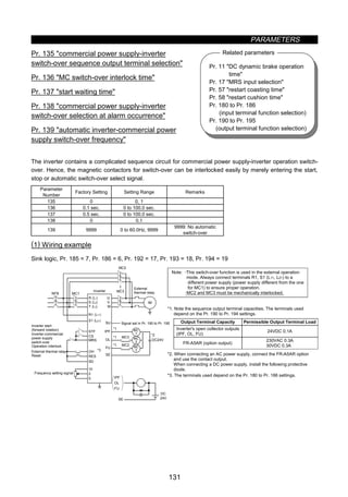
![PARAMETERS
132
· Roles of the magnetic contactors (MC1, MC2, MC3)
Magnetic
Contactor
Place of Installation Role
MC1
Between power supply and
inverter
Normally shorted with the following exception:
Opened only when an inverter fault occurs (shorted again by resetting)
MC2 Between power supply and motor
Shorted for commercial power supply operation, opened for inverter
operation
Shorted when an inverter fault occurs (selected with parameter, except
for external thermal relay operation)
MC3 Between inverter output and motor
Shorted for inverter operation, opened for commercial power supply
operation
Opened when an inverter fault occurs
I/O signals
1) When this function is used (Pr. 135 = 1), the input signals are switched on-off as indicated below:
MC Operation ({: ON, ×: OFF)
Signal Terminal Used Function On-Off
MC1 MC2 MC3
MRS MRS
Operation
enable/disable selection
Commercial power supply-
inverter operation enable
............................ON
Commercial power supply-
inverter operation disable
............................OFF
{
{
×
Unchanged
CS
Depending on
Pr. 180 to Pr.186
Inverter-commercial
power supply switch-
over
Inverter operation.ON
Commercial power supply
operation..............OFF
{
{
×
{
{
×
STF
(STR)
STF
(STR)
Inverter operation
command (invalid for
commercial power
supply) (Note)
Forward (reverse) rotation
............................ON
Stop .....................OFF
{
{
×
×
{
{
OH
Depending on
Pr. 180 to Pr.186
External thermal relay
input
Motor normal........ON
Motor fault............OFF
{
×
×
×
RES RES
Operating condition
initialization
Initialization..........ON
Normal operation .OFF
Unchanged
{
×
Unchanged
Note: · In the above MC Operation field, [-] indicates that MC1 is on, MC2 is off and MC3 is on in inverter
operation and MC1 is on, MC2 is off and MC3 is off in commercial power supply operation.
[Unchanged] indicates that the status before signal-on or -off is held.
· The CS signal only functions when the MRS signal is on. STF (STR) only functions when MRS and
CS are on.
· MC1 switches off when an inverter fault occurs.
· If the MRS signal is not switched on, neither commercial power supply nor inverter operation can be
performed.
2) The output signals are output as follows:
Signal Terminal Used Description
MC1 MC1's operation signal is output
MC2 MC2's operation signal is output
MC3
Depending on Pr. 190
to Pr. 195
MC3's operation signal is output](https://image.slidesharecdn.com/fr-a500-140613032347-phpapp01/85/Fr-a500-144-320.jpg)
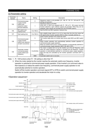
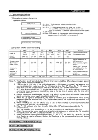
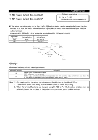
![PARAMETERS
136
Pr. 190 to Pr. 195
(output terminal function selection)
Related parameters
z Zero current detection (Pr. 152, Pr. 153)
Pr. 152 zero current detection level
Pr. 153 zero current detection time
When the inverter's output current falls to 0, torque will not be generated. This may cause a gravity drop
when the inverter is used in vertical lift application.
To prevent this, the output current zero signal can be output from the inverter to close the mechanical brake
when the output current has fallen to zero.
z If the output current remains lower than the Pr. 152 setting during inverter operation for longer than the time
set in Pr. 153, the zero current detection (Y13) signal is output from the inverter's open collector output
terminal.
(Use any of Pr. 190 to Pr. 195 to assign the terminal used for Y13 signal output.)
Parameter
Number
Factory Setting Setting Range
152 5.0% 0 to 200.0%
153 0.5 s 0 to 1 s
Output current 0 [A]
OFF ON
OFF ON
Pr.152
OFF ON
100 ms (Note)
Start signal
Pr. 152 zero current
detection level
Zero current detection
signal output
Pr. 153 detection time Pr. 153 detection time
Setting
Refer to the following list and set the parameters:
Parameter
Number
Description
152
Set the zero current detection level.
Set this parameter to define the percentage of the rated current at which the zero current will be detected.
153
Set the zero current detection time.
Set a period of time from when the output current drops to or below the Pr. 152 setting to when the zero current
detection signal (Y13) is output.
Note: 1. If the current falls below the preset detection level but the timing condition is not satisfied, the zero
current detection signal is held on for about 100ms.
2. This function is also valid during execution of the online or offline auto tuning.
3. When the terminal functions are changed using Pr. 190 to Pr. 195, the other functions may be
affected. Confirm the functions of the corresponding terminals before making settings.
CAUTION
The zero current detection level setting should not be too high, and the zero current detection
time setting not be too long. Otherwise, the detection signal may not be output when torque
is not generated at a low output current.
To prevent the machine and equipment from resulting in hazardous conditions by use of the
zero current detection signal, install a safety backup such as an emergency brake.](https://image.slidesharecdn.com/fr-a500-140613032347-phpapp01/85/Fr-a500-148-320.jpg)
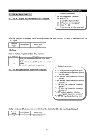
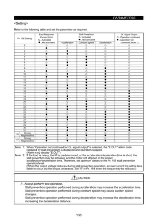
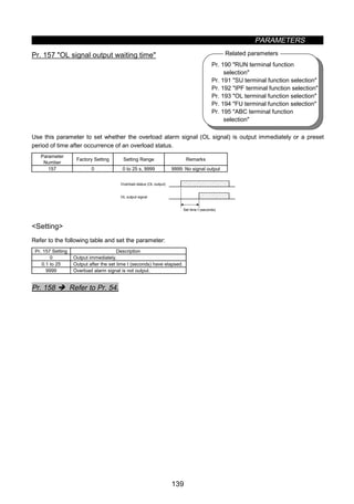
![PARAMETERS
140
z User group selection (Pr. 160, Pr. 173 to Pr. 176)
Pr. 160 user group read selection
Pr. 173 user group 1 registration
Pr. 174 user group 1 deletion
Pr. 175 user group 2 registration
Pr. 176 user group 2 deletion
From among all parameters, a total of 32 parameters can be registered to two different user groups.
The registered parameters may only be accessed for reading and writing.
Other parameters than those registered to the user groups cannot be read.
Parameter
Number
Factory Setting Setting Range Remarks
160 0 0, 1, 10, 11
173 0 0 to 999
174 0 0 to 999, 9999 9999: Batch deletion
175 0 0 to 999
176 0 0 to 999, 9999 9999: Batch deletion
Examples of use
(1) Parameter registration to user group (when registering Pr. 3 to user group 1)
FR-DU04 CONTROL PANEL
Hz
MON EXT PU
A
V
REV FWD
FR-DU04 CONTROL PANEL
Hz
MON EXT PU
A
V
REV FWD
FR-DU04 CONTROL PANEL
Hz
MON EXT PU
A
V
REV FWD
FR-DU04 CONTROL PANEL
Hz
MON EXT PU
A
V
REV FWD
FR-DU04 CONTROL PANEL
Hz
MON EXT PU
A
V
REV FWD
Pr. 173 reading
1) 2) 3) 4) 5)
SET SET
1.5 seconds
The number of parameters
registered for user setting
appears.
Using the [UP/DOWN] key,
choose the parameter number
to be registered.
Pr. 3 is registered to user
group 1.
Using the [UP/DOWN] key,
move to the next parameter
to be registered.
Using the [SET] key, make
registration.
.....
Flickering
.....
.....
.....
(2) Parameter deletion from user group (when deleting Pr. 5 from user group 1)
FR-DU04 CONTROL PANEL
Hz
MON EXT PU
A
V
REV FWD
FR-DU04 CONTROL PANEL
Hz
MON EXT PU
A
V
REV FWD
FR-DU04 CONTROL PANEL
Hz
MON EXT PU
A
V
REV FWD
FR-DU04 CONTROL PANEL
Hz
MON EXT PU
A
V
REV FWD
FR-DU04 CONTROL PANEL
Hz
MON EXT PU
A
V
REV FWD
Pr. 174 reading
1) 2) 3) 4) 5)
SET SET
1.5 seconds
The number of parameters
registered for user setting
appears.
Using the [UP/DOWN] key,
choose the parameter number
to be deleted.
Pr. 5 is deleted from user
group 1.
Using the [UP/DOWN] key,
choose the parameter to be
deleted.
Using the [SET] key, make
deletion.
.....
Flickering
.....
.....
.....
(3) By setting the required value in Pr. 160, make the user groups valid or invalid.
Pr. 160 Setting Description
0 All parameters can be accessed for reading and writing (Factory setting)
1 Parameters registered to user group 1 may only be accessed for reading and writing.
10 Parameters registered to user group 2 may only be accessed for reading and writing.
11 Parameters registered to user groups 1 and 2 may only be accessed for reading and writing.
Note: 1. Pr. 77, Pr. 160 and Pr. 991 values can always be read independently of the user group setting.
2. When Pr. 173 or Pr. 174 is read, the number of parameters registered to user group 1 appears.
When Pr. 175 or Pr. 176 is read, the number of parameters registered to user group 2 appears.
3. 0 set in the second digit of the 2-digit Pr. 160 setting is not displayed. However, it is displayed
when 0 is set in the first digit only.
4. When 9999 is set in Pr. 174 or Pr. 176, the parameters registered to the corresponding user
group is batch-deleted.
Pr. 162 to Pr. 165 Î Refer to Pr. 57.](https://image.slidesharecdn.com/fr-a500-140613032347-phpapp01/85/Fr-a500-152-320.jpg)
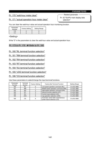
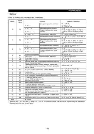
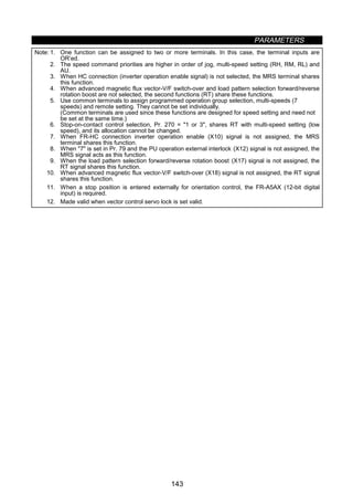
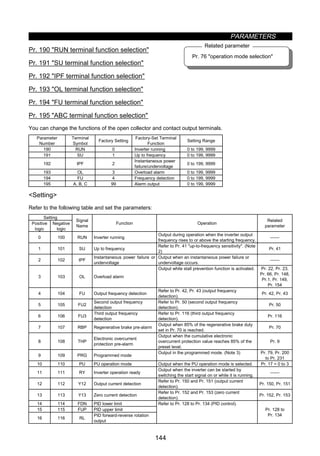
![PARAMETERS
145
Setting
Positive
logic
Negative
logic
Signal
Name
Function Operation
Related
parameter
17 MC1
Commercial power supply-
inverter switch-over MC1
18 MC2
Commercial power supply-
inverter switch-over MC2
19 MC3
Commercial power supply-
inverter switch-over MC3
Refer to Pr. 135 to Pr.139 (commercial power
supply-inverter switch-over).
Pr. 135 to
Pr. 139
20 120 BOF Brake opening request
Refer to Pr. 278 to Pr. 285 (brake sequence
functions).
Pr. 278 to
Pr. 285
25 125 FAN Fan fault output Output when a fan fault occurs.
26 126 FIN Fin overheat pre-alarm
Output when the heat sink temperature reaches
about 85% of the fin overheat protection
temperature.
127 ORA In-position
28 128 ORM Orientation error
When orientation is valid (only when FR-A5AP
option is loaded)
29 129 Y29 Overspeed detection
30 130 Y30 Forward running output
31 131 Y31 Reverse running output
For PLG feedback control, vector control
(only when the FR-A5AP option is loaded)
32 132 Y32 Regeneration status output
33 133 RY2 Operation ready 2
For vector control
(only when the FR-A5AP option is loaded)
98 198 LF Minor fault output
Output when a minor fault occurs. (Refer to page
179.)
99 199 ABC Alarm output
Output when the inverter's protective function is
activated to stop the output (major fault).
9999 No function
0 to 99: Positive logic
100 to 199: Negative logic
Note: 1. Under PLG feedback control (when the FR-A5AP option is loaded), the operations of the up-to-
frequency SU and frequency detection FU, FU2, FU3 are as follows:
SU, FU: The actual speed (frequency) provided by the PLG feedback signal is output at or above
the frequency specified for detection.
FU, FU3: The inverter output frequency is output at or above the frequency specified for
detection.
2. When the frequency setting is varied with the analog signal or the [UP/DOWN] key of the
operation panel, note that the output of the SU (up-to-frequency) signal may alternate between
ON and OFF due to that varying speed and the timing of the varying speed dependent on the
acceleration/deceleration time setting.
3. This signal is output when 5 is set in Pr. 79 operation mode selection and the external
operation mode is selected (the inverter goes into the programmed mode).
4. The same function may be set to more than one terminal.
5. When the function is activated, the terminal conducts with the settings of 0 to 99 and does not
conduct with the settings of 100 to 199.
6. Pr. 190 to Pr. 195 do not function if the values set are other than the above.
7. When Pr. 76 = 1 or 3, the output signals of the SU, IPF, OL and FU output terminals conform to
Pr. 76. When an inverter alarm occurs, the signal outputs are switched over to alarm code
outputs.
8. The output assignment of the RUN terminal and alarm output relay conforms to the above setting
independently of Pr. 76.](https://image.slidesharecdn.com/fr-a500-140613032347-phpapp01/85/Fr-a500-157-320.jpg)
![PARAMETERS
146
Pr. 77 parameter write disable
selection
Related parameter
z User initial value setting (Pr. 199)
Pr. 199 user's initial value setting
Among the parameters, you can set user-only parameter initial values. These values may be set to 16
parameters.
By performing user clear operation from the operation panel or parameter unit, you can initialize the
parameters to the user-set initial values. Note that the parameters of which initial values have not been set
are initialized to the factory settings by user clear operation.
z You can read the user's initial value list in the help mode of the parameter unit (FR-PU04).
Parameter
Number
Factory Setting Setting Range
199 0 0 to 999, 9999
The read Pr. 199 value is displayed as the number of parameters registered.
Setting example
(1) To set 1 in Pr. 7 and 2 in Pr. 8 as user's initial values. (Operation from the FR-DU04)
6) Through the above steps, the initial values of Pr. 7 and
Pr. 8 are registered.
1) Set 1 (target initial value) in Pr. 7.
2) Set 2 (target initial value) in Pr. 8.
3) Press the [SET] key to read Pr. 199. The number of
parameters having user's initial values are then displayed.
4) Further press the [SET] key for 1.5 seconds.
The parameter setting screen is then displayed.
5) Select Pr. 7 and Pr. 8 with the [UP/DOWN] key and
press the [SET] key for 1.5 seconds to enter.
The settings of the parameters whose numbers are set in Pr. 199 (i.e. Pr. 7 = 1, Pr. 8 = 2 in the above
example) are user's initial values.
(2) Deletion of user's initial values
By writing 9999 to Pr. 199 (and pressing the [SET] key for 1.5 seconds), the user's initial values
registered are batch-deleted.
Note: 1. When user's initial values for Pr. 902 to Pr. 905 are set, one parameter uses the area of two
parameters for registration.
2. As this setting is concerned with user-cleared initial values, the parameter numbers which cannot
be cleared cannot be set.
3. The operation panel (FR-DU04) cannot be used to refer to user's initial values.
4. Values cannot be registered to Pr. 201 to Pr. 231.](https://image.slidesharecdn.com/fr-a500-140613032347-phpapp01/85/Fr-a500-158-320.jpg)
![PARAMETERS
147
Pr. 76 alarm code output selection
Pr. 79 operation mode selection
Related parameters
z Programmed operation function (Pr. 200 to Pr. 231)
Pr. 200 program minute/second selection
Pr. 201 to Pr. 210 program setting 1 to 10
Pr. 211 to Pr. 220 program setting 11 to 20
Pr. 221 to Pr. 230 program setting 21 to 30
Pr. 231 time-of-day setting
z In programmed operation, automatic operation is performed under the control of the internal timer in
accordance with the preset time of day, running frequency and rotation direction.
z This function is made valid when the following parameter is set to the following value:
· Pr. 79 = 5 (programmed operation)
z You can select the time unit for programmed operation between minute/second and hour/minute.
z The start time of day, rotation direction and running frequency are defined as one point and every 10 points
are grouped into three:
· Group 1: Pr. 201 to Pr. 210
· Group 2: Pr. 211 to Pr. 220
· Group 3: Pr. 221 to Pr. 230
z Use Pr. 231 to set the time of day when programmed operation is started.
Parameter
Number
Factory
Setting
Setting Range Remarks
200 0 0 to 3
0, 2 [minute/second]
1, 3 [hour/minute]
201 to 210 0,9999,0
0 to 2
0 to 400, 9999
0 to 99.59
0 to 2: Rotation direction
0 to 400, 9999: Frequency
0 to 99.59: Time
211 to 220 0,9999,0
0 to 2
0 to 400, 9999
0 to 99.59
0 to 2: Rotation direction
0 to 400, 9999: Frequency
0 to 99.59: Time
221 to 230 0,9999,0
0 to 2: Rotation direction
0 to 400, 9999: Frequency
0 to 99.59: Time
0 to 2: Rotation direction
0 to 400, 9999: Frequency
0 to 99.59: Time
231 0 0 to 99.59
Wiring example
· For sink logic
STF
RH
RM
RL
STR
SD
FU
OL
PF
SU
SE
I
1
2
3
U,V,W
Output signal common
Programmed
operation start
Group selection
Timer reset
Input signal common
Inverter
Motor
Terminal function Pr. 79 = 5
Terminal function Pr. 76 = 3
Group run signals
(Open collector)
Time-out signal
R,S,T
〈L1,L2,L3〉](https://image.slidesharecdn.com/fr-a500-140613032347-phpapp01/85/Fr-a500-159-320.jpg)
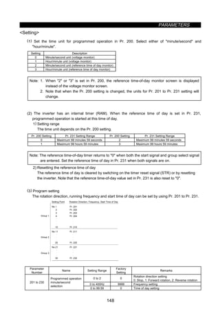
![PARAMETERS
149
Setting procedure
(Example: Set point No. 1, forward rotation, 30Hz, 4 hours 30 minutes)
1) Read Pr. 201 value.
2) Enter 1 (forward rotation) in Pr. 201 and press the [SET] key ([WRITE] key when using the FR-PU04
parameter unit).
3) Enter 30 (30Hz) and press the [SET] key ([WRITE] key when using the FR-PU04 parameter unit). (Note 1)
4) Enter 4.30 and press the [SET] key ([WRITE] key when using the FR-PU04 parameter unit). (Note 2)
5) Press the [UP] key to move to the next parameter (Pr. 202), and press the [SET] key ([READ] key when
using the FR-PU04 parameter unit) to display the current setting. Hereafter, press the [UP] key to advance
the parameter one by one.
Note 1: To make a stop, write 0 in the rotation direction and frequency. Set 9999 for no
setting.
Note 2: An error will result if 4.80 is entered (59 minutes or 59 seconds is exceeded).
· Assuming that operation has been programmed as indicated in the following table, the operation
pattern is as shown in the figure below:
No. Operation Parameter Setting
1
Forward rotation, 20Hz, 1 hour 0
minutes
Pr. 201 = 1, 20, 1:00
2 Stop, 3 hours 0 minutes Pr. 202 = 0, 0, 3:00
3
Reverse rotation, 30Hz, 4 hours 0
minutes
Pr. 203 = 2, 30, 4:00
4
Forward rotation, 10Hz, 6 hours 0
minutes
Pr. 204 = 1, 10, 6:00
5
Forward rotation, 35Hz, 7 hours 30
minutes
Pr. 205 = 1, 35, 7:30
6 Stop, 9 hours 0 minutes Pr. 206 = 0, 0, 9:00
Operation pattern
20Hz
0 1 3
4
6 9
10Hz
32 4 5 6
7:30
35Hz
Time of day
Set point 1
Forward
rotation
(4) Input signals
Name Description Signal Level Remarks
Group signal
RH (group 1)
RM (group 2)
RL (group 3)
Used to select the group for
programmed operation.
Timer reset signal (STR) Input to zero the reference time of day.
Programmed operation start
signal (STF)
Input to start programmed operation.
Photocoupler
isolated
May also be driven by
transistor. When ic = 10mA,
Vec0.5V should be satisfied.
(5) Output signals
Name Description Signal Level Remarks
Time-out signal (SU)
Output on completion of the operation of
the selected group and cleared on timer
reset.
Group select signals
(FU, OL, IPF)
Output during running of corresponding
group's program and cleared on timer
reset.
Open collector
output (isolated)
Permissible load
24VDC, 0.1A
Only when Pr. 76 = 3](https://image.slidesharecdn.com/fr-a500-140613032347-phpapp01/85/Fr-a500-161-320.jpg)
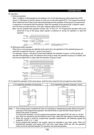
![PARAMETERS
151
Pr. 232 to Pr. 239 Î Refer to Pr. 4.
Pr. 240 Î Refer to Pr. 72.
z Cooling fan operation selection (Pr. 244)
Pr. 244 cooling fan operation selection
You can control the operation of the cooling fan built in the inverter (200V class, 1.5K or more).
Parameter
Number
Factory Setting Setting Range
244 0 0, 1
Setting
Setting Description
0 Operated at power on (independently of whether the inverter is running or at a stop).
1
Cooling fan on-off control valid
(The cooling fan is always on while the inverter is running. During a stop, the inverter status
is monitored and the fan switches on-off according to temperature.)
Reference
In either of the following cases, fan operation is regarded as faulty, [FN] is shown on the operation panel, and
the fan fault (FAN) and light fault (LF) signals are output. Use Pr. 190 to Pr. 195 (multi-function outputs) to
allocate the terminals used to output the FAN and LF signals.
1) Pr. 244 = 0
When the fan comes to a stop with power on.
2) Pr. 244 = 1
When the fan stops during the fan ON command while the inverter is running, or when the fan starts
during the fan OFF command.
Note: When the terminal functions are changed using Pr. 190 to Pr. 195, the other functions may be
affected. Confirm the functions of the corresponding terminals before making setting.](https://image.slidesharecdn.com/fr-a500-140613032347-phpapp01/85/Fr-a500-163-320.jpg)
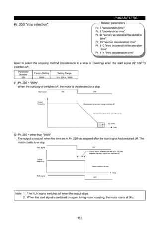
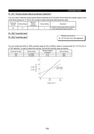
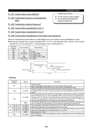
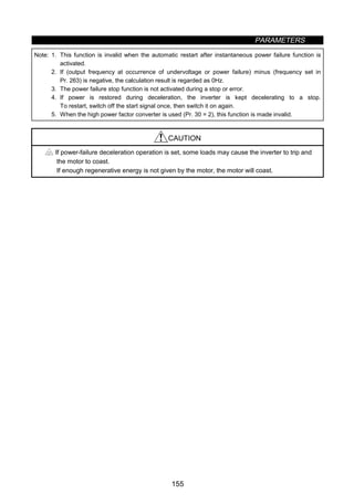
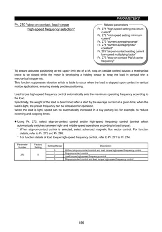
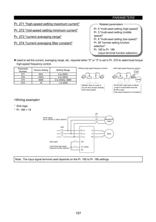
![PARAMETERS
158
Operation example
CS
STF (STR)
OFF
ON
Pr.5
Pr.4
Pr.5
A
× Pr.5
1
2 × Pr.5
1
2
B
Terminal
Less than 1/2 rated
current and driven load
Not less than rated current
or regenerative load
· When operation is performed with X19 (load detection high-speed frequency function selection) signal on,
the inverter automatically varies the maximum frequency between Pr. 4 “multi-speed setting (high speed)”
and Pr. 5 multi-speed setting (middle speed) settings as shown below according to the average current
flowing during acceleration from the frequency half of the Pr. 5 setting to the frequency set in Pr. 5.
Example: 1. If the average current is not more than half of the rated inverter current, the maximum
frequency is the value set in Pr. 4 as shown in operation example A.
2. If the average current is not less than the rated inverter current, the maximum frequency is the
value set in Pr. 5 as shown in operation example B.
Pr.4
(120Hz)
Pr.5
(60Hz)
Pr.271
(50%)
Pr.272
(100%)
Average current
Frequency
In this example, the frequency varies according to the current; 60Hz for 100% current
and 120Hz for 50% current.
Setting
1) Set 2 or 3 in Pr. 270.
2) Assign X19 (load detection high-speed frequency function selection) to the input terminal using any of
Pr. 180 to Pr. 186.
3) Refer to the following table and set the parameters:
Parameter
Number
Name Setting Description
4 Multi-speed setting (high speed) 0 to 400Hz Set the higher-speed frequency.
5 Multi-speed setting (middle speed) 0 to 400Hz Set the lower-speed frequency.
271 High-speed setting maximum current 0 to 200%
272 Mid-speed setting minimum current 0 to 200%
Set the upper and lower limits of the current at high and middle
speeds.
0 to 400Hz
(Average current during acceleration from (Pr. 273 × 1/2) Hz to
(Pr. 273) Hz can be achieved.
273 Current averaging range
9999
Average current during acceleration from (Pr. 5 × 1/2) Hz to
(Pr. 5) Hz is achieved.
274 Current averaging filter constant 1 to 4000
Set the time constant of the primary delay filter relative to the
output current.
(The time constant [ms] is 0.75 × Pr. 274 and the factory
setting is 12ms.) A larger setting provides higher stability but
poorer response.](https://image.slidesharecdn.com/fr-a500-140613032347-phpapp01/85/Fr-a500-170-320.jpg)
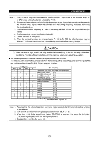
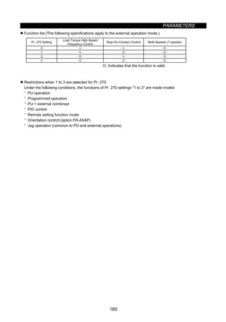
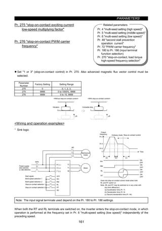
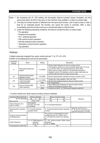
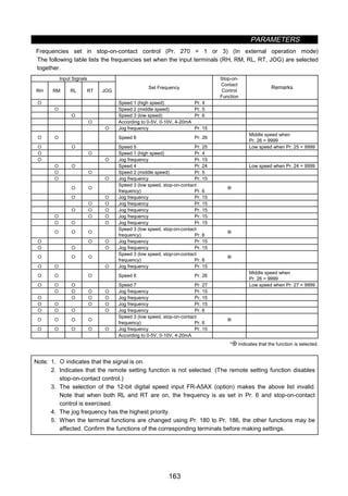
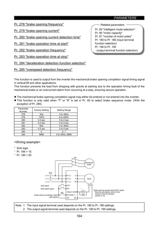
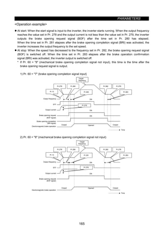
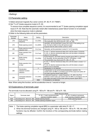
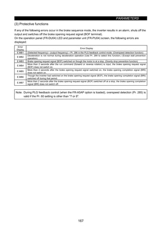
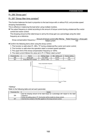
![PARAMETERS
170
Operation procedure
· When operation panel (FR-DU04) is used
8) Press the [STOP/RESET] key to stop the inverter.
1) Select the PU operation mode.
2) Set the running frequency.
3) Press the [SET] key.
4) Read Pr. 900 FM terminal calibration or Pr. 901 AM terminal calibration.
5) Press the [FWD] key to run the inverter. (Motor need not be connected.)
7) Press the [SET] key for about 1.5 seconds.
6) Hold down the [UP/DOWN] key to adjust the meter pointer to the required position.
(Depending on the setting, the pointer may take some time to move.)
Note: 1. Pr. 900 is factory-set to 1mA full-scale or 1440Hz FM output frequency at 60Hz. The maximum
pulse train output of terminal FM is 2400Hz.
2. When a frequency meter is connected across terminals FM-SD to monitor the running frequency,
the FM terminal output is filled to capacity at the factory setting if the maximum output frequency
reaches or exceeds 100Hz. In this case, the Pr. 55 setting must be changed to the maximum
frequency.
3. For the operation procedure using the parameter unit (FR-PU04), refer to the FR-PU04
instruction manual.](https://image.slidesharecdn.com/fr-a500-140613032347-phpapp01/85/Fr-a500-182-320.jpg)
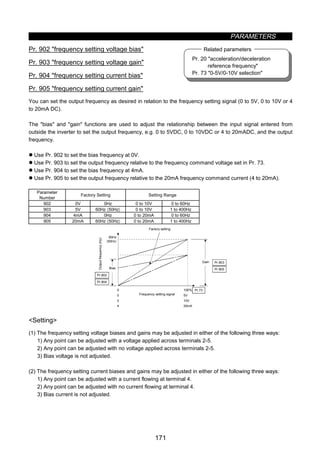
![PARAMETERS
172
Adjustment procedure Pr. 902 (Pr. 904) frequency setting voltage (current) bias
• When operation panel (FR-DU04) is used
Select the PU operation mode.
Read Pr. 902 (Pr. 904) value.
Press the [SET] key.
Using the [UP/DOWN] key, set the bias
frequency.
Press the [SET] key for about 1.5 seconds
The bias voltage (current) setting flickers.
Press the [SET] key.
The cursor moves to the next parameter.
Bias setting complete.
(1) Any point is adjusted with
a voltage (current) applied
(2) Any point is adjusted with
no voltage (current) applied
(3) Bias voltage (current)
is not adjusted.
Apply the bias voltage (current).
Press the [SET] key for about 1.5 seconds.
The analog voltage (current) monitor value
across terminals 2(4)-5 is displayed.
Using the [UP/DOWN] key, set
the bias voltage (current) in %.
[0% for 0V (0mA), 100% for 5V
(10V, 20mA)]
When the [UP] or [DOWN] key
is pressed, the present setting is
displayed.
*Pr. 903 to Pr. 905 can also be adjusted similarly using the above procedure.
Note: 1. If the Pr. 903 or Pr. 905 (gain adjustment) value is changed, the Pr. 20 value does not change.
The input signal to terminal 1 (frequency setting auxiliary input) is added to the frequency setting
signal.
2. For the operation procedure using the parameter unit (FR-PU04), refer to the FR-PU04 instruction
manual.](https://image.slidesharecdn.com/fr-a500-140613032347-phpapp01/85/Fr-a500-184-320.jpg)
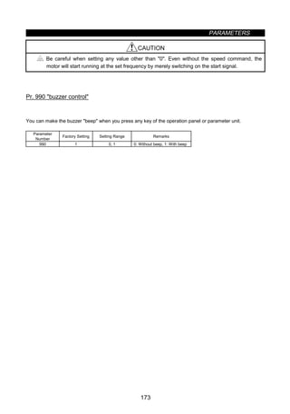
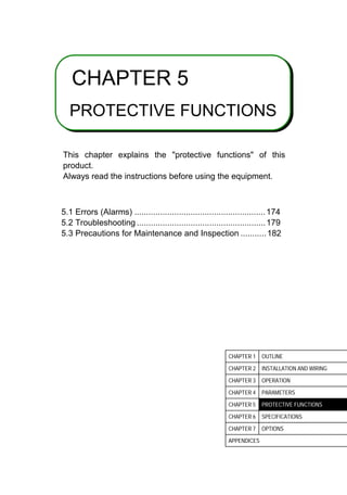
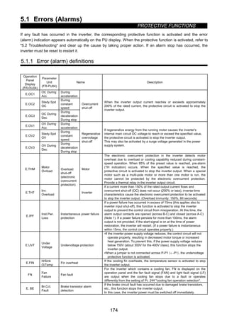
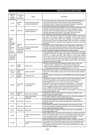
![PROTECTIVE FUNCTIONS
176
Operation
Panel
Display
(FR-DU04)
Parameter
Unit
(FR-PU04)
Name Description
Brake resistor overheat
protection
Inverters of 7.5K or less contain a brake resistor. When the regenerative
brake duty from the motor has reached 85% of the specified value,
pre-alarm (RB indication) occurs. If the specified value is exceeded, the
brake circuit operation is stopped temporarily to protect the brake resistor
from overheating. (If the brake is operated in this state, regenerative
overvoltage shut-off will occur.) When the brake resistor has cooled, the
brake operation is resumed.
E.MB1 to
MB7
Brake sequence error
This function stops the inverter output if a sequence error occurs during
the use of the brake sequence function (Pr. 278 to Pr. 285).
Err Error The inverter output is stopped if a malfunction occurs in the built-in CPU.
Note: 1. If Pr. 195 (A, B, C terminal function selection) is as set in the factory.
2. The terminals used must be allocated using Pr. 190 to Pr. 195.
3. External thermal relay operation is only activated when OH is set in any of Pr. 180 to Pr. 186
(input terminal function selection).
4. Indicates that the stall prevention operation level has been set to 150% (factory setting). If this
value is changed, stall prevention is operated at the new value.
5. Resetting method
When the protective function is activated and the inverter stops its output (the motor is coasted to
a stop), the inverter is kept stopped. Unless reset, the inverter cannot restart. To reset the
inverter, use any of the following methods: switch power off once, then on again; short reset
terminal RES-SD for more than 0.1 second, then open; press the [RESET] key of the parameter
unit (use the help function of the parameter unit). If RES-SD is kept shorted, the operation panel
will show Err. or the parameter unit will show that the inverter is being reset.](https://image.slidesharecdn.com/fr-a500-140613032347-phpapp01/85/Fr-a500-189-320.jpg)
![PROTECTIVE FUNCTIONS
177
z To know the operating status at the occurrence of an alarm
When any alarm has occurred, the display automatically switches to the indication of the corresponding
protective function (error). By pressing the [MODE] key at this point without resetting the inverter, the display
shows the output frequency. In this way, it is possible to know the running frequency at the occurrence of the
alarm. It is also possible to know the current in the same manner. However, these values are not stored in
memory and are erased when the inverter is reset.
5.1.2 Correspondences between digital and actual characters
There are the following correspondences between the actual alphanumeric characters and the digital
characters displayed on the operation panel:
Actual Digital Actual Digital Actual Digital
0
1
2
3
4
5
6
7
8
9
A
B
C
E
F
G
H
I
J
L
M
N
O
P
T
U
V
r
-
o
S](https://image.slidesharecdn.com/fr-a500-140613032347-phpapp01/85/Fr-a500-190-320.jpg)
![PROTECTIVE FUNCTIONS
178
5.1.3 Alarm code output
By setting Pr. 76 alarm code output selection, an alarm definition can be output as a 4-bit digital signal. This
signal is output from the open collector output terminals equipped as standard on the inverter.
Correlations between alarm definitions and alarm codes are as follows.
Output Terminal Signal On-OffOperation Panel
Display
(FR-DU04)
SU IPF OL FU
Alarm Code Alarm Output (across B-C)
E.OC1 0 0 0 1 1
E.OC2 0 0 1 0 2
E.OC3 0 0 1 1 3
Provided (Open)
E.OV1
E.OV2
E.OV3
0 1 0 0 4 Provided (Open)
E.THM 0 1 0 1 5
E.THT 0 1 1 0 6
Provided (Open)
E.IPF 0 1 1 1 7 Provided (Open)
E.UVT 1 0 0 0 8 Provided (Open)
E.FIN 1 0 0 1 9 Provided (Open)
E. BE 1 0 1 0 A Provided (Open)
E. GF 1 0 1 1 B Provided (Open)
E.OHT 1 1 0 0 C Provided (Open)
E.OLT 1 1 0 1 D
Not provided (Provided when OLT
is displayed) (Open)
E.OPT 1 1 1 0 E Provided (Open)
E.OP1 to E.OP3 1 1 1 0 E Provided (Open)
E. PE Provided (Open)
E.PUE Provided (Open)
E.RET Provided (Open)
E.LF Provided (Open)
E.CPU Provided (Open)
E.E6 Provided (Open)
E.E7
1 1 1 1 F
Provided (Open)
(Note) 0: Output transistor OFF, 1: Output transistor ON (common terminal SE)
The alarm output assumes that Pr. 195 setting is 99 (factory setting).
5.1.4 Resetting the inverter
The inverter can be reset by performing any of the following operations. Note that the electronic overcurrent
protection's internal heat calculation value and the number of retries are cleared (erased) by resetting the
inverter.
Operation 1: Using the operation panel (FR-DU04), press the [RESET] key to reset the inverter.
Operation 2: Switch power off once, then switch it on again.
Operation 3: Switch on the reset signal (RES).](https://image.slidesharecdn.com/fr-a500-140613032347-phpapp01/85/Fr-a500-191-320.jpg)
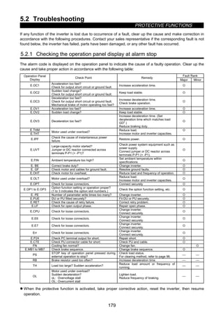
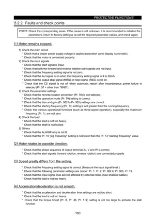
![PROTECTIVE FUNCTIONS
181
(5) Motor current is large.
· Check that the load is not too heavy.
· Check that the torque boost (Pr. 0, Pr. 46, Pr. 112) setting is not too large.
(6) Speed does not increase.
· Check that the maximum frequency (Pr. 1) setting is correct.
· Check that the load is not too heavy. (In agitators, etc., load may become heavy in winter.)
· Check that the torque boost (Pr. 0, Pr. 46, Pr. 112) setting is not too large to activate the stall
prevention function.
(7) Speed varies during operation.
During operation under advanced magnetic flux vector control, the output frequency varies with load
fluctuation between 0 and 2Hz. This is a normal operation and is not a fault.
1) Inspection of load
· Check that the load is not varying.
2) Inspection of input signal
· Check that the frequency setting signal is not varying.
· Check that the frequency setting signal is not affected by induced noise.
3) Others
· Check that the settings of the applied motor capacity (Pr. 80) and the number of applied motor poles
(Pr. 81) are correct for the inverter and motor capacities in advanced magnetic flux vector control.
· Check that the wiring length is within 30m (98.42 feet) in advanced magnetic flux vector control.
· Check that the wiring length is correct in V/F control.
(8) Operation mode is not changed properly.
If the operation mode is not changed properly, check the following:
1. External input signal .............Check that the STF or STR signal is off.
When it is on, the operation mode cannot be changed.
2. Parameter setting .................Check the Pr. 79 setting.
When the setting of Pr. 79 operation mode selection is 0 (factory
setting), switching input power on places the inverter in the external
operation mode. Press the operation panel's [MODE] key three times
and press the [UP] key (press the [PU] key for the parameter unit
(FR-PU04)). This changes the external operation mode into the PU
operation mode. For any other setting (1 to 8), the operation mode is
limited according to the setting.
(9) Operation panel (FR-DU04) display is not provided.
· Make sure that the operation panel is connected securely with the inverter.
(10) POWER lamp is not lit.
· Make sure that the wiring and installation are correct.](https://image.slidesharecdn.com/fr-a500-140613032347-phpapp01/85/Fr-a500-194-320.jpg)
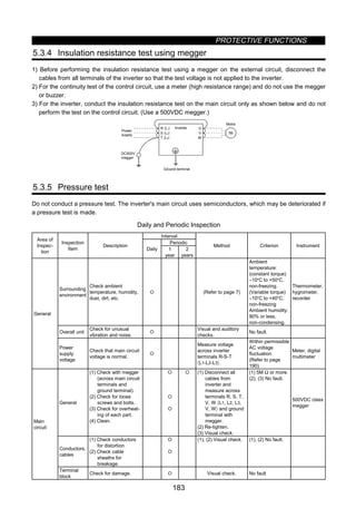
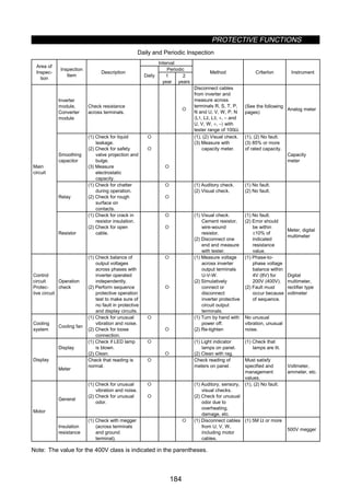
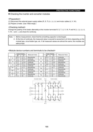
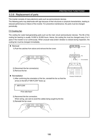
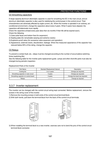
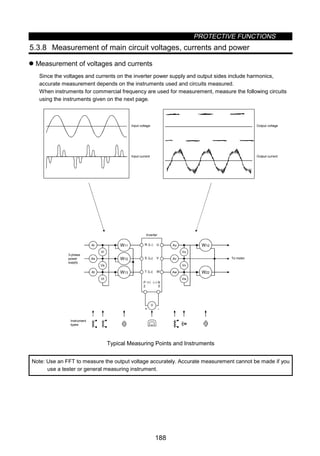
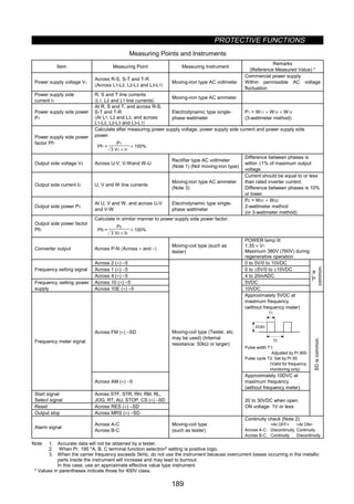
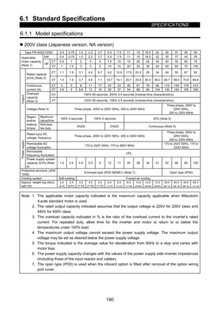
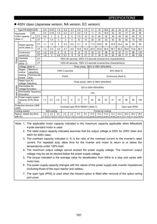
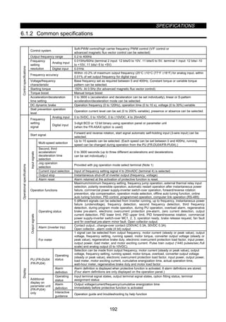
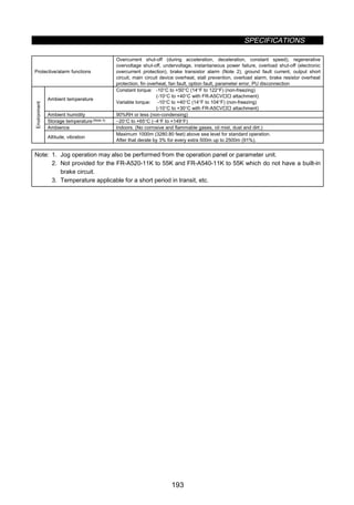
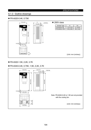
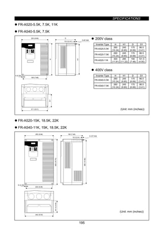
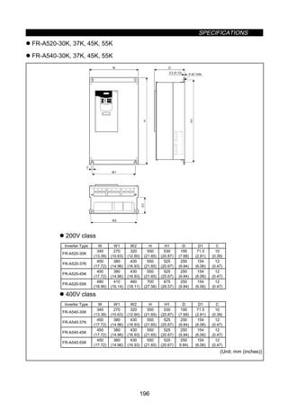
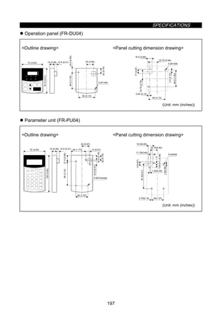
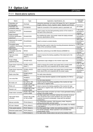
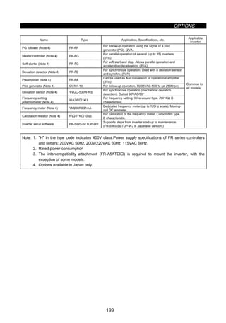
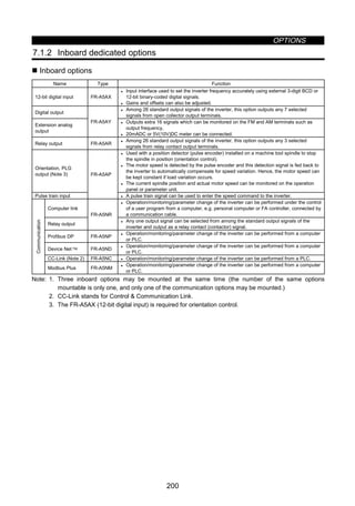
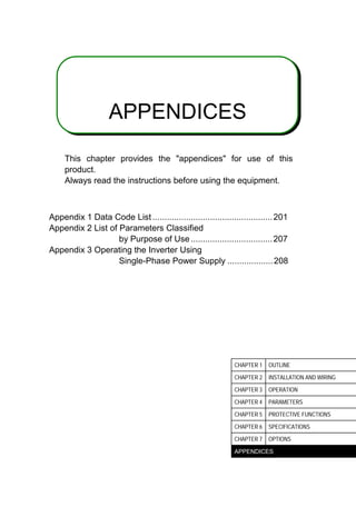
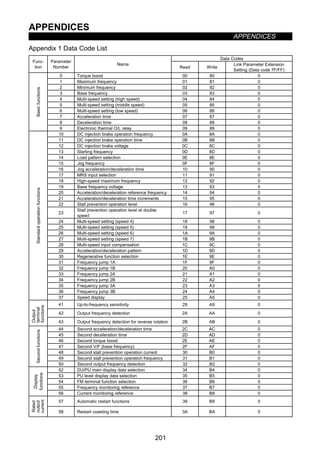
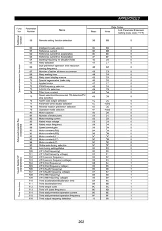
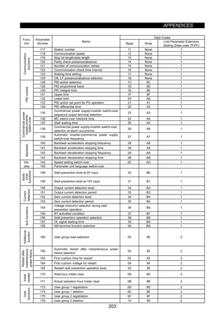
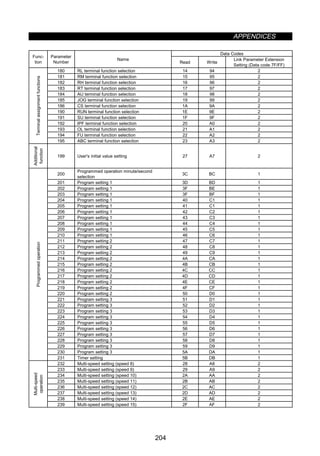
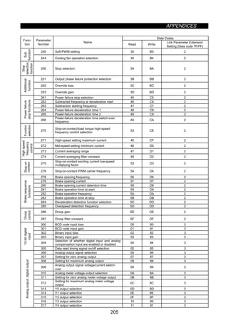
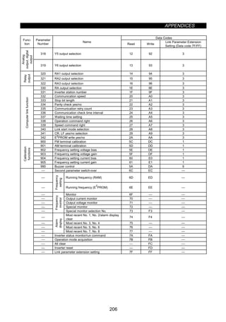
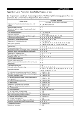
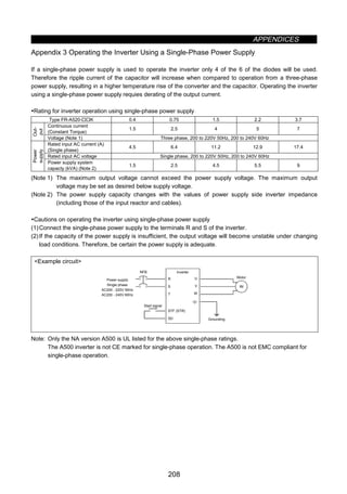
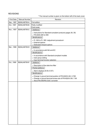


The document provides instructions for safely installing and operating an FR-A500 series transistorized inverter. It contains 3 sections: 1. Safety instructions that warn the user about electric shock and fire hazards, and measures to take to prevent injury. Proper handling, installation, wiring and maintenance procedures are outlined. 2. Descriptions of the inverter components and configuration. Instructions for removing covers and panels are included to access the interior for wiring and inspection. 3. Technical specifications and parameters for configuring the inverter for optimal control of AC motors. Settings for functions like acceleration/deceleration, frequency limits, electronic overcurrent protection and more are explained.

![Amp 250w mono[1]](https://cdn.slidesharecdn.com/ss_thumbnails/amp250wmono1-121227125036-phpapp01-thumbnail.jpg?width=640&height=640&fit=bounds)


![Tda2030[1]](https://cdn.slidesharecdn.com/ss_thumbnails/tda20301-140607151608-phpapp01-thumbnail.jpg?width=640&height=640&fit=bounds)


![Ct2000 pro plus_manual_english[1]](https://cdn.slidesharecdn.com/ss_thumbnails/ct2000proplusmanualenglish1-140613213527-phpapp02-thumbnail.jpg?width=640&height=640&fit=bounds)


![Ct2000 es manual_english_version_1[1].0](https://cdn.slidesharecdn.com/ss_thumbnails/ct2000esmanualenglishversion11-140613213448-phpapp01-thumbnail.jpg?width=640&height=640&fit=bounds)


