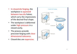
Forging
Dr.K. Santhy
Associate Professor
Department of Materials Science and Engineering
CARE Group of Institutions
Tiruchirappalli – 620 009
1
Content
• Classification of forging processes
• Forging equipment and operations
• Open die forging
• Closed die forging
• Plane strain forging analysis
• Forging defects
• Metallurgical variables associated with forging
• Powder metallurgy forging
• Residual stresses in forging
2
Forging
• Forging is the working of metal into a useful shape by
hammering or pressing.
• The oldest of the metalworking arts (primitive blacksmith).
• Replacement of machinery occurred during early the
Industrial revolution.
• Forging machines are now capable of making parts ranging in
size of a bolt to a turbine rotor.
• Most forging operations are carried out hot, although certain
metals may be cold-forged.
3
Range of cold, warm and hot forged parts
4
Examples such as coins, medals, cutlery and
various hand tools, as well as cold-coined hot
forged parts
5
• Forging is basically involves plastic deformation of
material between two dies to achieve desired
configuration. Depending upon complexity of the
part forging is carried out as open die forging and
closed die forging.
• In open die forging, the metal is compressed by
repeated blows by a mechanical hammer or
manually.
• In closed or impression die forging, the desired
configuration is obtained by squeezing the workpiece
between two shaped and closed dies.
6
Open Die Forging
Closed Die Forging
7
8
• Open-die forging is
carried out between
flat dies or dies of very
simple shape.
• The process is used for
mostly large objects or
when the number of
parts produced is
parts produced is
small.
• Open-die forging is
often used to preform
the workpiece for
closed-die forging.
9
• In closed die forging, the
workpiece is squeezed
between two die halves
which carry the impressions
of the desired final shape.
• The workpiece is deformed
under high pressure in a
closed cavity.
closed cavity.
• The process provide
precision forging with close
dimensional tolerance.
• Closed dies are expensive.
10
• On squeezing the die cavity gets completely filled and excess
material comes out around the periphery of the die as flash
which is later trimmed.
• Press forging and drop forging are two popular methods in
closed die forging.
• In press forging the metal is squeezed slowly by a hydraulic or
mechanical press and component is produced in a single
closing of die, hence the dimensional accuracy is much better
than drop forging.
• Both open and closed die forging processes are carried out in
hot as well as in cold state.
• In forging favourable grain orientation of metal is obtained
11
Grain orientation in forging
Forging Machining
12
Closed Die Forging
Billet Preshaped
Rough-
forge
Finishing
die
Trimming
die
Final
product
Flash is the excess metal, which
squirts out of the cavity as a
thick ribbon of metal.
Figure: Typical curve of forging load vs. stroke
for closed-die forging.
13
14
Functions of flash:
• Acts as a ‘safety value’ for excess metal
• Regulates the escape of metal
• Thin flash, builds up high pressure to ensure that the
metal fills all recesses of the die cavity.
Flash gutter:
For wide flash, a ridge is
provided
15
Metal flow is influenced by the part
geometry.
• Spherical and block like shapes are
easy
• Shapes with thin and long sections or
projections (ribs and webs) are
difficult
difficult
– due to high surface area per unit volume
– Friction and temperature effects are high
– Forging ties must be tapered to facilitate
removal of the finished parts.
– Draft allowance is ~50
16
Classification of Forging
Closed Die
Press
Forging
Forging
Closed Die
Forging Drop
Forging
Open die
forging
17
Metal will flow easily
to the nearest free
surface due to lowest
frictional path
18
Types of Forging Operation
• Fullering
• Edging
• Cogging
• Upsetting
• Upsetting
• Heading
• Swaging
• Radial forging etc.
19
Edging is used to shape the ends of the bars
and to gather metal. The metal flow is
confined in the horizontal direction but it is
free to flow laterally to fill the die.
20
Drawing is used to reduce the
cross-sectional area of the
workpiece with concurrent
increase in length.
Piercing and punching are
used to produce holes in
metals.
21
Fullering is used to reduce the cross-
sectional area of a portion of the stock.
The metal flow is outward and away
from the centre of the fuller. i.e.,
forging of connecting rod for an internal
combustion engine.
22
Fullers come in different shapes
23
Swaging is used to produce a bar
with a smaller diameter (using
concave dies).
• Swaging is a special type of
forging in which metal is
formed by a succession of rapid
hammer blows
• Swaging provides a reduced
round cross section suitable for
tapping, threading, upsetting or
other subsequent forming and
machining operations.
24
Classification of Forging Process
By equipment
1) Forging hammer or drop hammer
2) Press forging
By process
By process
1) Open - die forging
2) Closed - die forging
25
Hammer and press forging processes
• Forging hammers :
– Forces is supplied by a falling weight or ram
– Energy restricted machines (K.E. + P.E.)
– There are two basic types of forging hammers used;
• Board hammer
• Power hammer
• Forging presses :
– Stroke restricted machines
– There are two basic types of forging presses available;
• Mechanical presses
• Hydraulic presses
26
Board
hammer
Forging
Hammer
hammer
Steam
hammer
Presses
Mechanical
presses
Hydraulic
presses
27
Factors influences forging related to machine:
• Machine load > required load
• Machine energy > required energy
• No. of strokes per minute  production rate
• Contact time  time the workpiece remains in the die under
load (Die wear)
• Dimensional accuracy  stiffness of the product
28
Board hammer –forging hammer
• The upper die and ram are raised by friction
rolls gripping the board.
• After releasing the board, the ram falls under
gravity to produce the blow energy.
• The hammer can strike between 60-150 blows
per minute depending on size and capacity.
• The board hammer is an energy restricted
machine. The blow energy supplied equal the
potential energy due to the weight and the
height of the fall.
Potential energy = mgh
• This energy will be delivered to the metal
workpiece to produce plastic deformation and
elastic deformation of die. 29
• Dies are
expensive being
accurately
machined from
special alloys
(susceptible to
thermal shock).
thermal shock).
• Drop forging is
good for mass
production of
complex shapes.
• Shortest contact
time
30
Power hammer
• Power hammer provides greater
capacity, in which the ram is
accelerated on the downstroke by
steam or air pressure in addition to
gravity.
• Steam or air pressure is also used to
raise the ram on the upstroke.
• Energy of the blow can be controlled
whereas in the board hammer the
mass and height of fall are fixed
• Preferred for closed die forging than
board hammer
31
• Forging weight varies from pound to tons
• It has shortest contact time
• The total energy supplied to the blow in a power drop
hammer is given by
W= (½)mv2 + pAH = (mg +pA)H
Where, m = mass
v=velocity of ram at start of deformation
g = acceleration of gravity
p = air or steam pressure acting on ram cylinder on down stroke
A = area of ram cylinder
H = height of the ram drop
32
Disadvantage of Forging hammer:
• Accuracy is not possible
• Problem in ground shock, noise and vibration.
– Overcome this problems by counter blow hammer.
Recently High Energy Rate Forging (HERF) Machine is
available. It is used for mass production due to it’s
high velocity
33
Forging Press
• Using a hydraulic press or a mechanical press
to forge the metal, therefore, gives continuous
forming at a slower rate.
• Provide deeper penetration.
• Better properties (more homogeneous).
• Equipment is expensive.
34
Mechanical press forging
Crank press translates rotary motion
into reciprocating linear motion of the
press slide.
• The ram stroke is shorter than in a
hammer or hydraulic press.
• Presses are rated on the basis of the
force developed at the end of the
stroke.
• The blow press is squeeze the
workpiece than like the impact of the
hammer, therefore, dies can be less
massive and die life is longer than
with a hammer.
35
• The total energy supplied during the stroke of a press
is given by
Where I is moment of inertia of the flywheel
]
2
2
0
[
2
1
f
I
w 
 

Where I is moment of inertia of the flywheel
ω is angular velocity, ωo-original, ωf-after deformation
• Load rating 300 – 12,000 tons
36
Hydraulic Press Forging
• Hydraulic presses are load
restricted machines in which
hydraulic pressure moves a
piston in a cylinder.
• The full press load is available at
any point during the full stroke
of the ram. Therefore, hydraulic
presses are ideally suited for
extrusion-type forging
operation.
• Provide close-tolerance forging.
• Load 500 to 50,000 tons
37
• Due to slow speed,
contact time is longer at
the die-metal interface,
which causes problems
such as heat lost from
workpiece and die
deterioration.
• Hydraulic presses are
more expensive than
mechanical presses and
hammers
38
Screw Presses
• Used for hot and cold
forgings
• Ram is connected to rotary
joint of the spindle.
• The rotary motion of a fly
wheel converts into linear
motion of ram.
39
Typical values of velocity for different
forging equipment
Forging machine Velocity range, ms-1
Gravity drop hammer 3.6 – 4.8
Power drop hammer 3.0-9.0
HERF machine 6.0 -24.0
Mechanical press 0.06 -1.5
Hydraulic press 0.06-0.30
40
Forming machines
Machine Type Load
rating (F
in kN)
Available
Energy per
blow (W in kJ)
Ratio (W/F)
( in x 10-3)
Drop hammer 12250 106 1.3
Friction screw press 12250 8.0 6.4
Crank press 12250 25 16
Hydraulic press 12250 250 200
41
Die Materials
Required Properties:
• Thermal shock resistance
• Thermal fatigue resistance
• High temperature strength
• High wear resistance
• High toughness and ductility
• High hardenability
Die materials: alloyed
steels (with Cr, Mo, W, V),
tool steels, cast steels or
cast iron. (Heat treatments
• High hardenability
• High dimensional stability
during hardening
• High machinability
cast iron. (Heat treatments
such as nitriding or
chromium plating are
required to improve die life)
42
• Die life can be increased by
– Using composite die
– Using surface coating or self lubricating coating
• Ultra hard surface coating used on die surface due to
– Improve die life.
– Reduce energy input.
– Reduce die-related uptime and downtime.
– Reduce particulate emission from lubricants.
1) Carbon steels with 0.7-0.85% C are appropriate for small
tools and flat impressions.
2) Medium-alloyed tool steels for hammer dies.
3) Highly alloyed steels for high temperature resistant dies used
in presses and horizontal forging machines.
43
Die Failures
Different parts of dies are liable to permanent deformation
and wear resulting from mechanical and thermal fatigue.
44
Typical forging defects
• Incomplete die filling: Loose scale or lubricant residue that
accumulates and forms scale pockets on complex shape of
the die cause underfill. Incomplete rescaling of the
workpiece results in forged in scale on the finished part
• Die misalignment
• Incomplete forging penetration
– Normally observed in large workpiece which should be forge on
the forging press.
• Microstructural differences resulting in pronounced
property variation.
– Incomplete dendritic ingot structure. Observed by
macroetching of dendritic structure.
• Pitted surface, due to oxide scales occurring at high
temperature stick on the dies.
45
• Buckling, in upsetting forging.
– Subject to high compressive
stress of the workpiece develops
circumferential tensile stresses
– To avoid, concave dies are used
• Surface cracking Excessive
working of the surface at low
temperature or result of hot
shortness (due to high sulphur
Buckling
shortness (due to high sulphur
concentration in steel and
nickel.)
– due to temperature differential
between surface and centre
• Microcracking, due to residual
stress.
swaging
46
• Flash line crack, after trimming occurs more often in thin workpieces.
– Therefore, increase the thickness of the flash or relocating the flash position
or less critical region of the forging
– Avoided by hot trimming or stress relieving the forging prior to cold
trimming of the flash
• Cold shut or fold, is discontinuity produced when two surfaces of
metal fold against each other without welding completely, due to
flash or fin from prior forging steps is forced into the workpiece.
Due to
– Metal flows past part of the die cavity that has already filled
– Metal partly filled because the metal failed to fill in due to sharp corner
– Excessive chilling
– High friction
– Small die radius
47
• Internal cracking
– due to secondary tensile stress.
– During upsetting of a cylinder or a round results
circumferential tensile stresses
– Proper die design can minimize this type of cracking
– Less prevalent in closed die forging because lateral
compressive stresses are developed by interaction
workpiece with die wall
48
Residual Stresses
• Due to inhomogeneous deformation, RS is small in forging.
Most of the forging done at high temperature which reduces
the RS.
• Appreciable RS develops during quenching of steel forgings.
• Large forgings are subject to formation of small cracks or
flakes at the center of the cross section.
• In addition, flakes are associated with H2 gas
• Special cares are required for cooling large steel forgings.
– Vacuum degassed steel largely eliminates problems with flaking
– Large forgings are cooled slowly
– Hot workpieces are
• buried in ashes for several weeks
• Undergoes controlled cooling treatment
49
Consider forging stress ‘P’ acting on plate of
constant thickness ‘h’ under plane strain
condition.
1. Frictional shear stress τxy at the interface
of die and workpiece
2. Lateral pressure σx.
Fictional force resist the workpiece deformation
in lateral pressure. The equilibrium in x
direction is,
Forging in Plane Strain
Fig.: Stresses action on a plate forged in
plane strain
Von Mises’ yield criterion for plane strain
condition is,
If p=σz, then
plane strain
h
dx
d
dx
xy
h
x
d
dx
xy
h
x
d
x
h
x
xy
x








2
0
2
0
2
)
(









'
0
0
3
2
3
1



 


x
p 


 


 '
0
3
1
Differentiate the above equ. W.r.t x, then
( does not change with x)
Shearing stress is related to normal
pressure by coulomb’s law of sliding friction
(τxy = μp),
h
xy
dx
x
d
dx
dp 
 2



h
dx
p
dp
h
p
dx
dp


2
2




'
0

50
Integrate the above equation,
Apply boundary condition, xa σx=0 and
p=σ0’. Therefore,
h
dx
p
dp 
2


c
h
x
p ln
2
ln 

 
2
'
2
2
'
0
ln
ln
ln
2
'
0
ln
ln
a
x
h
a
C
C
h
a
p












The mean forging pressure is,
If the ratio a/h increases, the forming
pressure p and forming load rises rapidly .
 





























h
a
p
a
h
x
h
ax
x
a
p
a
dx
h
x
a
a
a
a
pdx
p







1
'
0
0
2
2
'
0
0
]
2
1
[
'
0
0
Usually μ is small number, ey=1+y+y2/2!+…
 
 
)
2
exp(
'
0
'
0
ln
2
ln
2
'
0
ln
2
ln
h
x
a
p
h
x
a
p
h
a
h
x
p
















 
]
2
1
[
'
0 h
x
a
p





pressure p and forming load rises rapidly .
Fig.: Distribution of normal stress and
longitudinal stress for compression
between plates.
51
• In high friction condition (sticking friction), the mean forging pressure is,
The forming load is dependent on the flow stress of the materials and the
geometry of the workpiece.
For example, a/h =8 then, .
To reduce the forming load,
– reduce friction coefficient μ









 1
2
'
0 h
a
p 
'
0
5

p
– reduce friction coefficient μ
– Changing the workpiece geometry
– Reducing by increasing the temperature.
'
0

52
Problem: A block of lead 25x25x150 mm3 is pressed between flat dies to a size
6.25x100x150 mm3. If the uniaxial flow stress σo = 6.9 MPa and μ = 0.25,
determine the pressure distribution over the 100 mm dimension at x = 0, 25
and 50 mm and the total forging load in the sticky friction condition.
Since 150mm dimension does not change the deformation is plane strain.
 
)
2
exp(
'
0 h
x
a
p



 0
3
2
'
0

 
53
Problem: A block of lead 25x25x150 mm3 is pressed between flat dies to a size
6.25x100x150 mm3. If the uniaxial flow stress σo = 6.9 MPa and μ = 0.25,
determine the pressure distribution over the 100 mm dimension at x = 0, 25 and
50 mm and the total forging load in the sticky friction condition.
Since 150mm dimension does not change the deformation is plane strain.
At the center line of the slap,
 
)
2
exp(
'
0 h
x
a
p



 0
3
2
'
0

 
  MPa
p
)
25
.
0
(
2
)
9
.
6
(
2
435
0
50
25
.
6
)
25
.
0
(
2
exp
3
)
9
.
6
(
2













The mean forging load at sticky friction condition,
Total forging load is, Load = stress X area = (39.8x106) x (150x10-3x100x10-3)
= 597kN
 
  MPa
p
MPa
p
8
50
50
25
.
6
)
25
.
0
(
2
exp
3
)
9
.
6
(
2
9
.
58
25
50
25
.
6
)
25
.
0
(
2
exp
3
)
9
.
6
(
2


























MPa
h
a
p 8
.
39
1
)
25
.
6
(
2
50
3
)
9
.
6
(
2
1
2
3
0
2
























54
Open-Die Forging
• In open die forging, the metal is
compressed by repeated blows by a
mechanical hammer or manually.
• Deals with large, relatively simple shapes
that are formed between simple dies in a
large hydraulic press or power hammer.
Ex: propeller shafts, rings, gun tubes and
pressure vessels.
pressure vessels.
• Workpiece is larger than the tool.
• Chief mode of deformation is
compression, workpiece is spreading in
lateral directions.
• Simplest open-die forging operation is
cogging a billet between fat tools to
reduce the cross sectional area without
changing the final shape.
55
Coefficient of spread S,
Width can be expressed as length by using
constant volume relationship,
The coefficient of elongation,
Fig.: Cogging operation. Shaded
are shows where contact
)
1
/
0
ln(
)
0
/
1
ln(
_
_
h
h
w
w
n
contractio
thickness
elongation
width
S 

1
0
0
0
1
1
1 
l
w
h
l
w
h
0
)
/
1
ln(
)
/
1
ln(
)
/
1
ln( 

 o
l
l
o
w
w
o
h
h
The coefficient of elongation,
If S=1, the workpiece spread
S=0, all the deformation go into elongation.
are shows where contact
would occur between
workpiece and upper die.
)
1
/
0
ln(
)
0
/
1
ln(
_
_
1
h
h
l
l
n
contractio
thickness
elongation
length
S 


S can be expressed by bite ratio (b/wo), since
The spread law, where β=spread ratio = w1/w0
γ=squeeze ratio=h0/h1
o
w
b
o
w
b
S
/
1
/


S










 1
56
Since only part of the surface is undergo deformation at a time, there is
possibility of surface laps. For a given geometry, the critical deformation
produce laps. Since,
• Squeeze ratio s h0/h1 should be ≤ 1.3 which make billet is deformed
through to the center
• Bite ratio b/w0 should be ≥ 1/3 to minimize inhomogeneous deformation.
The load required to forge a flat section in the open dies is,
Where C is a constraint factor to allow for inhomogeneous deformation.
AC
P 

57
Closed Die Forging
• In closed die forging, the desired configuration is obtained by
squeezing the workpiece between two shaped and closed
dies.
• The deformation in closed die forging is very complex.
• The success of the forging operation requires the
understanding of
– Flow stress of the materials
Frictional conditions
– Frictional conditions
– Flow of the materials to fill the die
58
• Special problems in it is, rapid cooling of the workpiece by the colder dies
results
– Raise of flow stress
– Raise of loads,
– Incomplete die fill and
– Loss of dimensional tolerance.
• To avoid this problem, isothermal forging is used. For forging aerospace
materials, the die which is made up of superalloy is heated for isothermal
forging.
• The design of a component, place important role in closed die forging. It
involves
– Workpiece volume and weight
– no. of preforming steps and their configuration
– Flash dimensions in preforming and finishing dies
– The load and energy requirements for each forging operation
Proper design assures, defect-free flow, complete die fill and minimum flash
loss. For that it is important to understand the metal flow.
• Classification of closed die forging are listed in diagram.
59
60
61
Figure: Flow diagram for computer-aided design (CAD) and computer-
aided manufacturing (CAM) systems applied to closed die forging
N/C – numerically controlled machine
APT – specialized computer language describing geometric changes
produced in metal cutting which is hear of N/C machining
62
General considerations for preform design
• Area of each cross section = area in the finished cross section
+ flash.
• Concave radii of the preform > radii on the final forging part.
• Cross section of the preform should be higher and narrower
than the final cross section, so as to accentuate upsetting flow
and minimise extrusion flow.
Shape with thin and long
sections or projections (ribs
and webs) are more difficult to
process because they have
higher surface area per unit
volume increasing friction and
temperature effects.
63
General rules of closed-die design
• The die set should be designed for smooth metal flow – symmetry
dies (spherical or block like) are the easier than thin and long
section.
• Shape changes in section are to be avoided.
• Dies should be designed for the minimum flash to do the job.
• Generous fillet dimensions should be allowed, therefore, forging
dies must be tapered or drafted to facilitate removal of the finished
piece.
• Draft allowance is approximately 3-5o outside and 7-10o inside.
• Dies with inclined angles should have counterlock to prevent the
dies from sliding apart from each other due to side thrust.
64
Forming textures
• Redistribution of metal structures occurring during forming
process involves two principle components;
– redistribution of inclusions and
– crystallographic orientation of the grains
1) The redistribution of inclusions
65
• Crystallographic orientation of the grains
Mainly epitaxial, dendritic or
equiaxed grains
Cast iron
Fibre structure in forged steels
Redistribution of grains in the
working directions
66
Effect of forging on microstructure
• The formation of a grain structure in forged parts is elongated
in the direction of the deformation.
• The metal flow during forging provides fibrous microstructure
(revealed by etching). This structure gives better mechanical
properties in the plane of maximum strain but (perhaps)
lower across the thickness.
• The workpiece often undergo recrystallisation, therefore,
provide finer grains compared to the cast dendritic structure
resulting in improved mechanical properties.
67
Powder Metallurgy Forging
• Now, P/M forging is in growing area
• Advantage:
– Improved materials utilisation through reduction or elimination of
machining
– Forming to final size in one forging stoke
– Uniformity of structure and reduced directionality of properties
relative to conventionally forged parts.
• Working in a sintered powdered parts preform introduces
new aspects to the mechanics of interconnected parts.
68
• Challenges:
– P/M parts contains dispersion of interconnected voids
– Work-piece volume is decreases during plastic
deformation as the elimination of porosity.
– Presence of voids decreases the local ductility which may
lead to fracture during forging. Forming limit concept has
to be applied to overcome this issue.
– Presence of voids increases the surface area which may
increases the oxidation and contamination reaction.
69
• The basic plasticity mechanics of a porous powder metallurgy
preform described with the relationship of densification and
plastic Poisson ratio ‘ν’.
2
5
.
0 








• Kuhn modified the von Mises’ yield criterion by considering
the porous materials densification with plastic deformation,
5
.
0 






t


 
     
  
2
/
1
1
3
3
2
2
1
2
1
3
2
3
2
2
2
1
2
1
2
, 














 














o
70

Metal-forming-Unit-2.1.pdf

  • 1.
    Forging Dr.K. Santhy Associate Professor Departmentof Materials Science and Engineering CARE Group of Institutions Tiruchirappalli – 620 009 1
  • 2.
    Content • Classification offorging processes • Forging equipment and operations • Open die forging • Closed die forging • Plane strain forging analysis • Plane strain forging analysis • Forging defects • Metallurgical variables associated with forging • Powder metallurgy forging • Residual stresses in forging 2
  • 3.
    Forging • Forging isthe working of metal into a useful shape by hammering or pressing. • The oldest of the metalworking arts (primitive blacksmith). • Replacement of machinery occurred during early the Industrial revolution. Industrial revolution. • Forging machines are now capable of making parts ranging in size of a bolt to a turbine rotor. • Most forging operations are carried out hot, although certain metals may be cold-forged. 3
  • 4.
    Range of cold,warm and hot forged parts 4
  • 5.
    Examples such ascoins, medals, cutlery and various hand tools, as well as cold-coined hot forged parts 5
  • 6.
    • Forging isbasically involves plastic deformation of material between two dies to achieve desired configuration. Depending upon complexity of the part forging is carried out as open die forging and closed die forging. • In open die forging, the metal is compressed by repeated blows by a mechanical hammer or repeated blows by a mechanical hammer or manually. • In closed or impression die forging, the desired configuration is obtained by squeezing the workpiece between two shaped and closed dies. 6
  • 7.
  • 8.
  • 9.
    • Open-die forgingis carried out between flat dies or dies of very simple shape. • The process is used for mostly large objects or when the number of parts produced is parts produced is small. • Open-die forging is often used to preform the workpiece for closed-die forging. 9
  • 10.
    • In closeddie forging, the workpiece is squeezed between two die halves which carry the impressions of the desired final shape. • The workpiece is deformed under high pressure in a closed cavity. closed cavity. • The process provide precision forging with close dimensional tolerance. • Closed dies are expensive. 10
  • 11.
    • On squeezingthe die cavity gets completely filled and excess material comes out around the periphery of the die as flash which is later trimmed. • Press forging and drop forging are two popular methods in closed die forging. • In press forging the metal is squeezed slowly by a hydraulic or mechanical press and component is produced in a single closing of die, hence the dimensional accuracy is much better closing of die, hence the dimensional accuracy is much better than drop forging. • Both open and closed die forging processes are carried out in hot as well as in cold state. • In forging favourable grain orientation of metal is obtained 11
  • 12.
    Grain orientation inforging Forging Machining 12
  • 13.
    Closed Die Forging BilletPreshaped Rough- forge Finishing die Trimming die Final product Flash is the excess metal, which squirts out of the cavity as a thick ribbon of metal. Figure: Typical curve of forging load vs. stroke for closed-die forging. 13
  • 14.
  • 15.
    Functions of flash: •Acts as a ‘safety value’ for excess metal • Regulates the escape of metal • Thin flash, builds up high pressure to ensure that the • Thin flash, builds up high pressure to ensure that the metal fills all recesses of the die cavity. Flash gutter: For wide flash, a ridge is provided 15
  • 16.
    Metal flow isinfluenced by the part geometry. • Spherical and block like shapes are easy • Shapes with thin and long sections or projections (ribs and webs) are difficult difficult – due to high surface area per unit volume – Friction and temperature effects are high – Forging ties must be tapered to facilitate removal of the finished parts. – Draft allowance is ~50 16
  • 17.
    Classification of Forging ClosedDie Press Forging Forging Closed Die Forging Drop Forging Open die forging 17
  • 18.
    Metal will floweasily to the nearest free surface due to lowest frictional path 18
  • 19.
    Types of ForgingOperation • Fullering • Edging • Cogging • Upsetting • Upsetting • Heading • Swaging • Radial forging etc. 19
  • 20.
    Edging is usedto shape the ends of the bars and to gather metal. The metal flow is confined in the horizontal direction but it is free to flow laterally to fill the die. 20
  • 21.
    Drawing is usedto reduce the cross-sectional area of the workpiece with concurrent increase in length. Piercing and punching are used to produce holes in metals. 21
  • 22.
    Fullering is usedto reduce the cross- sectional area of a portion of the stock. The metal flow is outward and away from the centre of the fuller. i.e., forging of connecting rod for an internal combustion engine. 22
  • 23.
    Fullers come indifferent shapes 23
  • 24.
    Swaging is usedto produce a bar with a smaller diameter (using concave dies). • Swaging is a special type of forging in which metal is formed by a succession of rapid formed by a succession of rapid hammer blows • Swaging provides a reduced round cross section suitable for tapping, threading, upsetting or other subsequent forming and machining operations. 24
  • 25.
    Classification of ForgingProcess By equipment 1) Forging hammer or drop hammer 2) Press forging By process By process 1) Open - die forging 2) Closed - die forging 25
  • 26.
    Hammer and pressforging processes • Forging hammers : – Forces is supplied by a falling weight or ram – Energy restricted machines (K.E. + P.E.) – There are two basic types of forging hammers used; • Board hammer • Power hammer • Forging presses : – Stroke restricted machines – There are two basic types of forging presses available; • Mechanical presses • Hydraulic presses 26
  • 27.
  • 28.
    Factors influences forgingrelated to machine: • Machine load > required load • Machine energy > required energy • No. of strokes per minute  production rate • Contact time  time the workpiece remains in the die under • Contact time  time the workpiece remains in the die under load (Die wear) • Dimensional accuracy  stiffness of the product 28
  • 29.
    Board hammer –forginghammer • The upper die and ram are raised by friction rolls gripping the board. • After releasing the board, the ram falls under gravity to produce the blow energy. • The hammer can strike between 60-150 blows per minute depending on size and capacity. • The board hammer is an energy restricted machine. The blow energy supplied equal the potential energy due to the weight and the height of the fall. Potential energy = mgh • This energy will be delivered to the metal workpiece to produce plastic deformation and elastic deformation of die. 29
  • 30.
    • Dies are expensivebeing accurately machined from special alloys (susceptible to thermal shock). thermal shock). • Drop forging is good for mass production of complex shapes. • Shortest contact time 30
  • 31.
    Power hammer • Powerhammer provides greater capacity, in which the ram is accelerated on the downstroke by steam or air pressure in addition to gravity. • Steam or air pressure is also used to • Steam or air pressure is also used to raise the ram on the upstroke. • Energy of the blow can be controlled whereas in the board hammer the mass and height of fall are fixed • Preferred for closed die forging than board hammer 31
  • 32.
    • Forging weightvaries from pound to tons • It has shortest contact time • The total energy supplied to the blow in a power drop hammer is given by W= (½)mv2 + pAH = (mg +pA)H Where, m = mass v=velocity of ram at start of deformation g = acceleration of gravity g = acceleration of gravity p = air or steam pressure acting on ram cylinder on down stroke A = area of ram cylinder H = height of the ram drop 32
  • 33.
    Disadvantage of Forginghammer: • Accuracy is not possible • Problem in ground shock, noise and vibration. – Overcome this problems by counter blow hammer. Recently High Energy Rate Forging (HERF) Machine is Recently High Energy Rate Forging (HERF) Machine is available. It is used for mass production due to it’s high velocity 33
  • 34.
    Forging Press • Usinga hydraulic press or a mechanical press to forge the metal, therefore, gives continuous forming at a slower rate. • Provide deeper penetration. • Provide deeper penetration. • Better properties (more homogeneous). • Equipment is expensive. 34
  • 35.
    Mechanical press forging Crankpress translates rotary motion into reciprocating linear motion of the press slide. • The ram stroke is shorter than in a hammer or hydraulic press. • Presses are rated on the basis of the • Presses are rated on the basis of the force developed at the end of the stroke. • The blow press is squeeze the workpiece than like the impact of the hammer, therefore, dies can be less massive and die life is longer than with a hammer. 35
  • 36.
    • The totalenergy supplied during the stroke of a press is given by Where I is moment of inertia of the flywheel ] 2 2 0 [ 2 1 f I w     Where I is moment of inertia of the flywheel ω is angular velocity, ωo-original, ωf-after deformation • Load rating 300 – 12,000 tons 36
  • 37.
    Hydraulic Press Forging •Hydraulic presses are load restricted machines in which hydraulic pressure moves a piston in a cylinder. • The full press load is available at • The full press load is available at any point during the full stroke of the ram. Therefore, hydraulic presses are ideally suited for extrusion-type forging operation. • Provide close-tolerance forging. • Load 500 to 50,000 tons 37
  • 38.
    • Due toslow speed, contact time is longer at the die-metal interface, which causes problems such as heat lost from such as heat lost from workpiece and die deterioration. • Hydraulic presses are more expensive than mechanical presses and hammers 38
  • 39.
    Screw Presses • Usedfor hot and cold forgings • Ram is connected to rotary joint of the spindle. joint of the spindle. • The rotary motion of a fly wheel converts into linear motion of ram. 39
  • 40.
    Typical values ofvelocity for different forging equipment Forging machine Velocity range, ms-1 Gravity drop hammer 3.6 – 4.8 Power drop hammer 3.0-9.0 Power drop hammer 3.0-9.0 HERF machine 6.0 -24.0 Mechanical press 0.06 -1.5 Hydraulic press 0.06-0.30 40
  • 41.
    Forming machines Machine TypeLoad rating (F in kN) Available Energy per blow (W in kJ) Ratio (W/F) ( in x 10-3) Drop hammer 12250 106 1.3 Friction screw press 12250 8.0 6.4 Friction screw press 12250 8.0 6.4 Crank press 12250 25 16 Hydraulic press 12250 250 200 41
  • 42.
    Die Materials Required Properties: •Thermal shock resistance • Thermal fatigue resistance • High temperature strength • High wear resistance • High toughness and ductility • High hardenability Die materials: alloyed steels (with Cr, Mo, W, V), tool steels, cast steels or cast iron. (Heat treatments • High hardenability • High dimensional stability during hardening • High machinability cast iron. (Heat treatments such as nitriding or chromium plating are required to improve die life) 42
  • 43.
    • Die lifecan be increased by – Using composite die – Using surface coating or self lubricating coating • Ultra hard surface coating used on die surface due to – Improve die life. – Reduce energy input. – Reduce die-related uptime and downtime. – Reduce die-related uptime and downtime. – Reduce particulate emission from lubricants. 1) Carbon steels with 0.7-0.85% C are appropriate for small tools and flat impressions. 2) Medium-alloyed tool steels for hammer dies. 3) Highly alloyed steels for high temperature resistant dies used in presses and horizontal forging machines. 43
  • 44.
    Die Failures Different partsof dies are liable to permanent deformation and wear resulting from mechanical and thermal fatigue. 44
  • 45.
    Typical forging defects •Incomplete die filling: Loose scale or lubricant residue that accumulates and forms scale pockets on complex shape of the die cause underfill. Incomplete rescaling of the workpiece results in forged in scale on the finished part • Die misalignment • Incomplete forging penetration – Normally observed in large workpiece which should be forge on – Normally observed in large workpiece which should be forge on the forging press. • Microstructural differences resulting in pronounced property variation. – Incomplete dendritic ingot structure. Observed by macroetching of dendritic structure. • Pitted surface, due to oxide scales occurring at high temperature stick on the dies. 45
  • 46.
    • Buckling, inupsetting forging. – Subject to high compressive stress of the workpiece develops circumferential tensile stresses – To avoid, concave dies are used • Surface cracking Excessive working of the surface at low temperature or result of hot shortness (due to high sulphur Buckling shortness (due to high sulphur concentration in steel and nickel.) – due to temperature differential between surface and centre • Microcracking, due to residual stress. swaging 46
  • 47.
    • Flash linecrack, after trimming occurs more often in thin workpieces. – Therefore, increase the thickness of the flash or relocating the flash position or less critical region of the forging – Avoided by hot trimming or stress relieving the forging prior to cold trimming of the flash trimming of the flash • Cold shut or fold, is discontinuity produced when two surfaces of metal fold against each other without welding completely, due to flash or fin from prior forging steps is forced into the workpiece. Due to – Metal flows past part of the die cavity that has already filled – Metal partly filled because the metal failed to fill in due to sharp corner – Excessive chilling – High friction – Small die radius 47
  • 48.
    • Internal cracking –due to secondary tensile stress. – During upsetting of a cylinder or a round results circumferential tensile stresses – Proper die design can minimize this type of cracking – Less prevalent in closed die forging because lateral compressive stresses are developed by interaction workpiece with die wall 48
  • 49.
    Residual Stresses • Dueto inhomogeneous deformation, RS is small in forging. Most of the forging done at high temperature which reduces the RS. • Appreciable RS develops during quenching of steel forgings. • Large forgings are subject to formation of small cracks or flakes at the center of the cross section. flakes at the center of the cross section. • In addition, flakes are associated with H2 gas • Special cares are required for cooling large steel forgings. – Vacuum degassed steel largely eliminates problems with flaking – Large forgings are cooled slowly – Hot workpieces are • buried in ashes for several weeks • Undergoes controlled cooling treatment 49
  • 50.
    Consider forging stress‘P’ acting on plate of constant thickness ‘h’ under plane strain condition. 1. Frictional shear stress τxy at the interface of die and workpiece 2. Lateral pressure σx. Fictional force resist the workpiece deformation in lateral pressure. The equilibrium in x direction is, Forging in Plane Strain Fig.: Stresses action on a plate forged in plane strain Von Mises’ yield criterion for plane strain condition is, If p=σz, then plane strain h dx d dx xy h x d dx xy h x d x h x xy x         2 0 2 0 2 ) (          ' 0 0 3 2 3 1        x p         ' 0 3 1 Differentiate the above equ. W.r.t x, then ( does not change with x) Shearing stress is related to normal pressure by coulomb’s law of sliding friction (τxy = μp), h xy dx x d dx dp   2    h dx p dp h p dx dp   2 2     ' 0  50
  • 51.
    Integrate the aboveequation, Apply boundary condition, xa σx=0 and p=σ0’. Therefore, h dx p dp  2   c h x p ln 2 ln     2 ' 2 2 ' 0 ln ln ln 2 ' 0 ln ln a x h a C C h a p             The mean forging pressure is, If the ratio a/h increases, the forming pressure p and forming load rises rapidly .                                h a p a h x h ax x a p a dx h x a a a a pdx p        1 ' 0 0 2 2 ' 0 0 ] 2 1 [ ' 0 0 Usually μ is small number, ey=1+y+y2/2!+…     ) 2 exp( ' 0 ' 0 ln 2 ln 2 ' 0 ln 2 ln h x a p h x a p h a h x p                   ] 2 1 [ ' 0 h x a p      pressure p and forming load rises rapidly . Fig.: Distribution of normal stress and longitudinal stress for compression between plates. 51
  • 52.
    • In highfriction condition (sticking friction), the mean forging pressure is, The forming load is dependent on the flow stress of the materials and the geometry of the workpiece. For example, a/h =8 then, . To reduce the forming load, – reduce friction coefficient μ           1 2 ' 0 h a p  ' 0 5  p – reduce friction coefficient μ – Changing the workpiece geometry – Reducing by increasing the temperature. ' 0  52
  • 53.
    Problem: A blockof lead 25x25x150 mm3 is pressed between flat dies to a size 6.25x100x150 mm3. If the uniaxial flow stress σo = 6.9 MPa and μ = 0.25, determine the pressure distribution over the 100 mm dimension at x = 0, 25 and 50 mm and the total forging load in the sticky friction condition. Since 150mm dimension does not change the deformation is plane strain.   ) 2 exp( ' 0 h x a p     0 3 2 ' 0    53
  • 54.
    Problem: A blockof lead 25x25x150 mm3 is pressed between flat dies to a size 6.25x100x150 mm3. If the uniaxial flow stress σo = 6.9 MPa and μ = 0.25, determine the pressure distribution over the 100 mm dimension at x = 0, 25 and 50 mm and the total forging load in the sticky friction condition. Since 150mm dimension does not change the deformation is plane strain. At the center line of the slap,   ) 2 exp( ' 0 h x a p     0 3 2 ' 0      MPa p ) 25 . 0 ( 2 ) 9 . 6 ( 2 435 0 50 25 . 6 ) 25 . 0 ( 2 exp 3 ) 9 . 6 ( 2              The mean forging load at sticky friction condition, Total forging load is, Load = stress X area = (39.8x106) x (150x10-3x100x10-3) = 597kN     MPa p MPa p 8 50 50 25 . 6 ) 25 . 0 ( 2 exp 3 ) 9 . 6 ( 2 9 . 58 25 50 25 . 6 ) 25 . 0 ( 2 exp 3 ) 9 . 6 ( 2                           MPa h a p 8 . 39 1 ) 25 . 6 ( 2 50 3 ) 9 . 6 ( 2 1 2 3 0 2                         54
  • 55.
    Open-Die Forging • Inopen die forging, the metal is compressed by repeated blows by a mechanical hammer or manually. • Deals with large, relatively simple shapes that are formed between simple dies in a large hydraulic press or power hammer. Ex: propeller shafts, rings, gun tubes and pressure vessels. pressure vessels. • Workpiece is larger than the tool. • Chief mode of deformation is compression, workpiece is spreading in lateral directions. • Simplest open-die forging operation is cogging a billet between fat tools to reduce the cross sectional area without changing the final shape. 55
  • 56.
    Coefficient of spreadS, Width can be expressed as length by using constant volume relationship, The coefficient of elongation, Fig.: Cogging operation. Shaded are shows where contact ) 1 / 0 ln( ) 0 / 1 ln( _ _ h h w w n contractio thickness elongation width S   1 0 0 0 1 1 1  l w h l w h 0 ) / 1 ln( ) / 1 ln( ) / 1 ln(    o l l o w w o h h The coefficient of elongation, If S=1, the workpiece spread S=0, all the deformation go into elongation. are shows where contact would occur between workpiece and upper die. ) 1 / 0 ln( ) 0 / 1 ln( _ _ 1 h h l l n contractio thickness elongation length S    S can be expressed by bite ratio (b/wo), since The spread law, where β=spread ratio = w1/w0 γ=squeeze ratio=h0/h1 o w b o w b S / 1 /   S            1 56
  • 57.
    Since only partof the surface is undergo deformation at a time, there is possibility of surface laps. For a given geometry, the critical deformation produce laps. Since, • Squeeze ratio s h0/h1 should be ≤ 1.3 which make billet is deformed through to the center • Bite ratio b/w0 should be ≥ 1/3 to minimize inhomogeneous deformation. The load required to forge a flat section in the open dies is, Where C is a constraint factor to allow for inhomogeneous deformation. AC P   57
  • 58.
    Closed Die Forging •In closed die forging, the desired configuration is obtained by squeezing the workpiece between two shaped and closed dies. • The deformation in closed die forging is very complex. • The success of the forging operation requires the understanding of – Flow stress of the materials Frictional conditions – Frictional conditions – Flow of the materials to fill the die 58
  • 59.
    • Special problemsin it is, rapid cooling of the workpiece by the colder dies results – Raise of flow stress – Raise of loads, – Incomplete die fill and – Loss of dimensional tolerance. • To avoid this problem, isothermal forging is used. For forging aerospace materials, the die which is made up of superalloy is heated for isothermal forging. • The design of a component, place important role in closed die forging. It • The design of a component, place important role in closed die forging. It involves – Workpiece volume and weight – no. of preforming steps and their configuration – Flash dimensions in preforming and finishing dies – The load and energy requirements for each forging operation Proper design assures, defect-free flow, complete die fill and minimum flash loss. For that it is important to understand the metal flow. • Classification of closed die forging are listed in diagram. 59
  • 60.
  • 61.
  • 62.
    Figure: Flow diagramfor computer-aided design (CAD) and computer- aided manufacturing (CAM) systems applied to closed die forging N/C – numerically controlled machine APT – specialized computer language describing geometric changes produced in metal cutting which is hear of N/C machining 62
  • 63.
    General considerations forpreform design • Area of each cross section = area in the finished cross section + flash. • Concave radii of the preform > radii on the final forging part. • Cross section of the preform should be higher and narrower than the final cross section, so as to accentuate upsetting flow and minimise extrusion flow. Shape with thin and long sections or projections (ribs and webs) are more difficult to process because they have higher surface area per unit volume increasing friction and temperature effects. 63
  • 64.
    General rules ofclosed-die design • The die set should be designed for smooth metal flow – symmetry dies (spherical or block like) are the easier than thin and long section. • Shape changes in section are to be avoided. • Dies should be designed for the minimum flash to do the job. • Generous fillet dimensions should be allowed, therefore, forging dies must be tapered or drafted to facilitate removal of the finished piece. • Draft allowance is approximately 3-5o outside and 7-10o inside. • Draft allowance is approximately 3-5o outside and 7-10o inside. • Dies with inclined angles should have counterlock to prevent the dies from sliding apart from each other due to side thrust. 64
  • 65.
    Forming textures • Redistributionof metal structures occurring during forming process involves two principle components; – redistribution of inclusions and – crystallographic orientation of the grains 1) The redistribution of inclusions 65
  • 66.
    • Crystallographic orientationof the grains Mainly epitaxial, dendritic or equiaxed grains Cast iron Fibre structure in forged steels Redistribution of grains in the working directions 66
  • 67.
    Effect of forgingon microstructure • The formation of a grain structure in forged parts is elongated in the direction of the deformation. in the direction of the deformation. • The metal flow during forging provides fibrous microstructure (revealed by etching). This structure gives better mechanical properties in the plane of maximum strain but (perhaps) lower across the thickness. • The workpiece often undergo recrystallisation, therefore, provide finer grains compared to the cast dendritic structure resulting in improved mechanical properties. 67
  • 68.
    Powder Metallurgy Forging •Now, P/M forging is in growing area • Advantage: – Improved materials utilisation through reduction or elimination of machining – Forming to final size in one forging stoke – Forming to final size in one forging stoke – Uniformity of structure and reduced directionality of properties relative to conventionally forged parts. • Working in a sintered powdered parts preform introduces new aspects to the mechanics of interconnected parts. 68
  • 69.
    • Challenges: – P/Mparts contains dispersion of interconnected voids – Work-piece volume is decreases during plastic deformation as the elimination of porosity. – Presence of voids decreases the local ductility which may – Presence of voids decreases the local ductility which may lead to fracture during forging. Forming limit concept has to be applied to overcome this issue. – Presence of voids increases the surface area which may increases the oxidation and contamination reaction. 69
  • 70.
    • The basicplasticity mechanics of a porous powder metallurgy preform described with the relationship of densification and plastic Poisson ratio ‘ν’. 2 5 . 0          • Kuhn modified the von Mises’ yield criterion by considering the porous materials densification with plastic deformation, 5 . 0        t              2 / 1 1 3 3 2 2 1 2 1 3 2 3 2 2 2 1 2 1 2 ,                                o 70